S/N Ratio
Low Pass Crossover (Variable)
Bass Boost (Variable)
Frequency Response
THD@ RMS Output
Fuse Values
Power Max (2 Ohms)
Remote Subwoofer Level Control
LK 602
175W x 2
110W x 2
350W x 1
Power RMS (4 Ohms)
Bridged (4 Ohms) Power
High Pass Crossover
Continuously Variable 35Hz ~ 155Hz
Tri-mode Operation
Inputs
LK 902
300W x 2
200W x 2
600W x 1
LK 454
125W x 4
75W x 4
250W x 2
LK 654
150W x 4
100W x 4
300W x 2
9Hz - 50KHz (+/- 3dB)
100Hz 100Hz 100Hz 100Hz
25A x 1
- - - - - - - - - - - -
(11-7/8"W x 2-7/8"H x ...) 16-5/8"L13-3/16"L14-11/16"L10-3/8"L
MODEL
Channnel Separation
Damping Factor
Full range pre-amp output
Dimensions
0~ +18dB 0~ +18dB 0~ +18dB
0~ +18dB
YES YES YES YES
YES YES YES
YES
0.01%
90dB
125+
103 dB 103 dB 103 dB 103 dB
0.01% 0.01% 0.01%
90dB 90dB 90dB
125+ 125+ 125+
15A x 1 15A x 1 30A x 2
YES YES
FEATURES
Heavy Duty Aluminum Alloy Heatsink
Class A-B Operation
Continuously Variable Low Pass Crossover
(35Hz to 155Hz)
18dB Bass Boost
Remote Subwoofer Level Control
High Pass Crossover (100Hz)
Two Channel Amplifiers LK 602 , LK 902
Two Channel BridgeableMOSFET Amplifier
Tri-Mode Capable
Heavy Duty AluminumAlloy Heatsink
Class A-B Operation
Continuously VariableLow PassCrossover
(35Hz to 155Hz)
18dB Bass Boost
Remote Subwoofer LevelControl
High PassCrossover (100Hz)
Continuously VariableInput Gain Control
Nickel Plated RCAAnd Speaker LevelInputs
Remote Turn On /Turn Off Circuit
MOSFET Pulse WidthModulated PowerSupply
2 Ohm StableStereo Operation WithOutput
Power Increase
Soft Turn-on Circuit
Thermal and SpeakerShort Protection Circuitry
LED PowerAnd Protection Indicators
Four Channel Amplifiers LK 454, LK 654
Four Channel BridgeableMOSFET Amplifier
The amplifier protection circuitry will disable the amplifier if the inputs are overloaded, short-circuited or
extremely high temperature conditions are detected. When the protection mode is in operation, the LED indicator
on the front panel will be illuminated, indicating the amplifier has gone into a self-preservation mode.
Attempting to powerup the amplifieragain.
If you observe that the protection LED is lit, please check the system carefully to determine what has caused the
protection circuit to engage. The amplifier can be reset by turning the remote power off and then on again. If the
amplifier shuts down due to a thermal overload condition, please allow it to cool down before powering up. If the
amplifier shuts down because of an input overload or short circuit, Be sure to repaire these conditions before
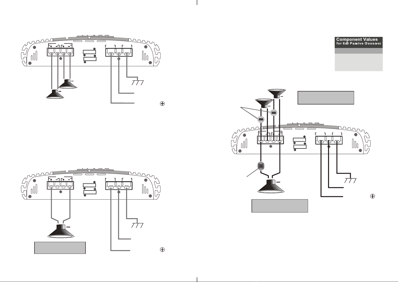
The IMPACTLK series amplifiersfeature built-in electroniccrossovers.
The 2 Channel amplifiers feature a continuously variable low pass and high pass crossover.
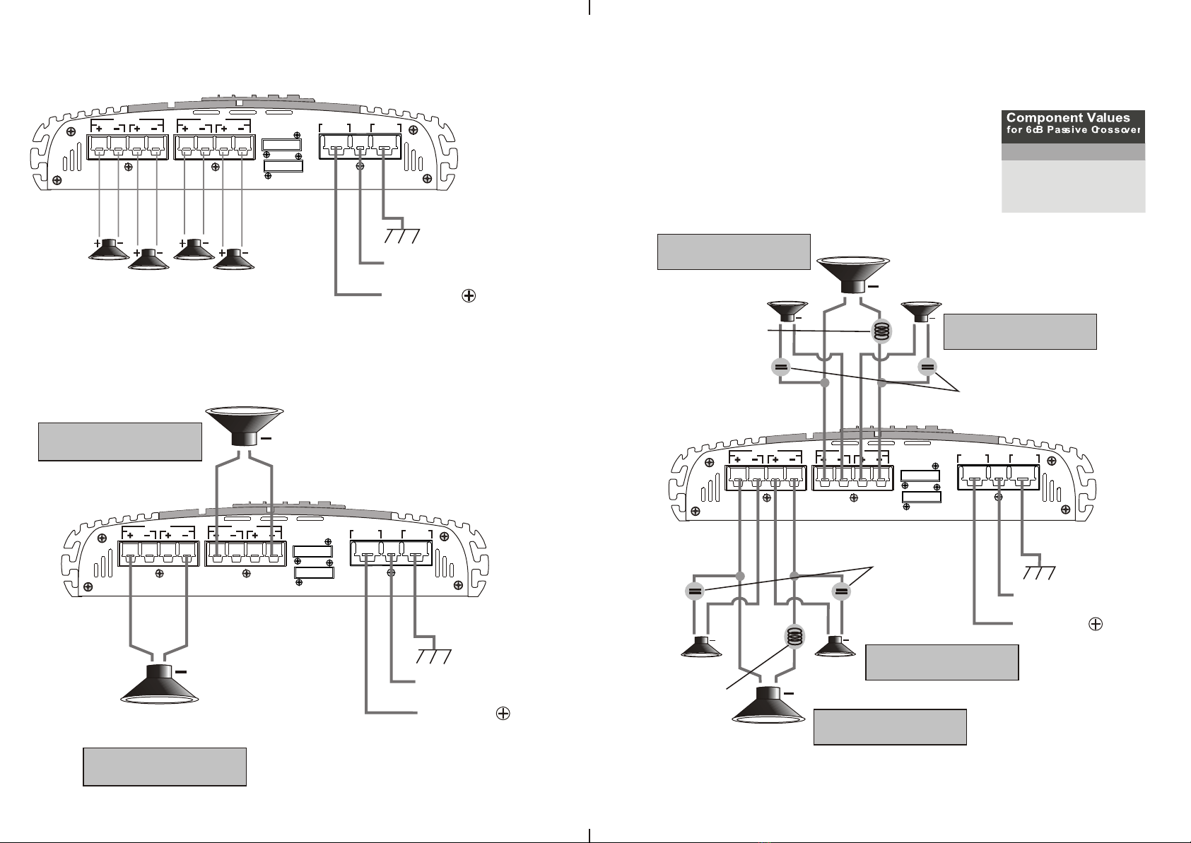
The 4 Channel amplifiers feature a pair of continuously variable low pass and high pass crossovers.
Built-in Crossover
The IMPACT LK series amplifiers have been designed with 100% MOSFET power supplies, ensuring
extremely quick switching response for plenty of clean power.
Protection Circuitry
SPECIFICATIONS
Continuously VariableInput Gain Control
Nickel Plated RCAAnd Speaker LevelInputs
Remote Turn On /Turn Off Circuit
MOSFET Pulse WidthModulated PowerSupply
2 Ohm StableStereo Operation WithOutput
Power Increase
Soft Turn-on Circuit
Thermal and SpeakerShort ProtectionCircuitry
LED PowerAnd ProtectionIndicators
Electrical Wiring
The protection circuitto engage.
The IMPACT LK Series amplifier was designed tooperate effectively at loads down 2 Ohms.This
means that you can install four 8Ohm speakers per channel when using parallel wiring. Increasing
the number of woofers per channel at lowfrequencies (up to 100Hz) produces an acoustic
coupling effect. This acoustic coupling increases your power output by 3 dB per speaker.
When operating at 2Ohms, the amplifiers will increase their output power by approximately 50%. The
current draw will also increase by about the sameamount, so be sure youhave enough current torun the
amplifiers into a 2 Ohmload. If you lack adequate current, your music reproduction will be distorted.
Please note: The gain control ofany car audio amplifier should notbe mistaken for avolume control. It is
a sophisticated device, designed to matchthe output level of your audiosource unit to theinput level of
the amplifier. Do not adjustthis input level to maximum unlessyour input level requiresit. Ignoring these
instructions will result in an inputoverload to the amplifier, and excessive audio distortion. Itcan also cause
2 Ohm Operation (in stereo mode)
Wire the amplifier directly to the carbattery.Make sure there is circuit protection (such as a fuse) onthe
Positive power lead,within 18 inches of the battery.
All IMPACT LK series power amplifiers are equipped with easy top access screw terminals. These
terminals are n in order to ensure excellent electrical contact and to resist corrosion.ickel-plated
When making electrical connections tothe amplifier, please observe the following:
Use at least 8 gauge orheavier wire for power and ground connections.
For the ground connection, usethe shortest possible wire to a good chassis ground point.
Wire the Remote connection to the remoteturn-on lead of yourequalizer or head unit.In some cases
this may be the power antennalead of the head unit.
Fuses
Fuses protect both the amplifier and the electrical system of your vehicle from faulty conditions. If you must
replace the fuse in your ampliifier, use a fuse of exactly the same type and rating. A different type or rating may
result in damage or cause afire.
-2- -3-