IN-ECO RGH9028-2 User manual
Rotary Hammer
EN Rotary Hammer
RGH9028-2 RGH9028-2M URGH9028-2 RGH9028-26
RGH9028-28 RGH9028S-2 RGH9028-29
ingcoglobal
INGCO GLOBAL
2|English
The symbols in instruction manual and the label on the tool
Double insulated for additional protection.
Read the instruction manual before using.
CE conformity.
Wear safety glasses, hearing protection and dust mask.
Waste electrical products should not be disposed of with household waste.
Please recycle where facilities exist. Check with your Local Authority or
retailer for recycling advice.
Safety alert.
Please only use the accessories supported by the manufacture.

3|English
follow the warnings and instructions may result in electric shock, fire and/or
serious injury.
Save all warnings and instructions for future reference.
The term "power tool" in the warnings refers to your mains-operated (corded)
power tool or battery-operated (cordless) power tool.
1) Work area safety
a) Keep work area clean and well lit. Cluttered and dark areas invite
accidents.
b) Do not operate power tools in explosive atmospheres, such as
in the presence of flammable liquids, gases or dust. Power tools
create sparks which may ignite the dust or fumes.
c) Keep children and bystanders away while operating a power
tool. Distractions can cause you to lose control.
2) Electrical safety
a) Power tool plugs must match the outlet. Never modify the plug
in any way. Do not use any adapter plugs with earthed
(grounded) power tools. Unmodified plugs and matching outlets will
reduce risk of electric shock.
b) Avoid body contact with earthed or grounded surfaces such as
pipes, radiators, ranges and refrigerators. There is an increased
risk of electric shock if your body is earthed or grounded.
c) Do not expose power tools to rain or wet conditions. Water
entering a power tool will increase the risk of electricshock.
d) Do not abuse the cord. Never use the cord for carrying, pulling
or unplugging the power tool. Keep cord away from heat, oil,
sharp edges or moving parts. Damaged or entangled cords
increase the risk of electric shock.
e) When operating a power tool outdoors, use an extension cord
suitable for outdoor use. Use of a cord suitable for outdoor use
reduces the risk of electric shock.
f) If operating a power tools in a damp location is unavoidable, use
WARNING Read all safety warnings and all instructions. Failure to
GENERAL POWER TOOL SAFETY WARNINGS

4|English
a residual current device (RCD) protected supply. Use of an RCD
reduces the risk of electric shock.
3) Personal safety
a) Stay alert, watch what you are doing and use common sense
when operating a power tool. Do not use a power tool while you
are tired or under the influence of drugs, alcohol or medication.
A moment of inattention while operating power tools may result in
serious personal injury.
b) Use personal protective equipment. Always wear eye protection.
Protective equipment such as dust mask, non-skid safety shoes,
hard hat, or hearing protection used for appropriate conditions will
reduce personal injuries.
c) Prevent unintentional starting. Ensure the switch is in the off-
position before connecting to power source and/or battery pack,
picking up or carrying the tool. Carrying power tools with your
finger on the switch or energizing power tools that have the switch on
invites accidents.
d) Remove any adjusting key or wrench before turning the power
tool on. A wrench or a key left attached to a rotating part of the
power tool may result in personal injury.
e) Do not overreach. Keep proper footing and balance at all times.
This enables better control of the power tool in unexpected
situations.
f) Dress properly. Do not wear loose clothing or jewellery. Keep
your hair, clothing and gloves away from moving parts. Loose
clothes, jewellery or long hair can be caught in moving parts.
g) If devices are provided for the connection of dust extraction and
collection facilities, ensure these are connected and properly
used. Use of dust collection can reduce dust-related hazards.
4) Power tool use and care
a) Do not force the power tool. Use the correct power tool for your
application. The correct power tool will do the job better and safer at
the rate for which it was designed.
b) Do not use the power tool if the switch does not turn it on and off.
Any power tool that cannot be controlled with the switch is dangerous

5|English
and must be repaired.
c) Disconnect the plug from the power source and/or the battery
pack from the power tool before making any adjustments,
changing accessories, or storing power tools. Such preventive
safety measures reduce the risk of starting the power tool accidentally.
d) Store idle power tools out of the reach of children and do not allow
persons unfamiliar with the power tool or these instructions to
operate the power tool. Power tools are dangerous in the hands of
untrained users.
e) Maintain power tools. Check for misalignment or binding of
moving parts, breakage of parts and any other condition that may
affect the power tools operation. If damaged, have the power tool
repaired before use. Many accidents are caused by poorly maintained
power tools.
f) Keep cutting tools sharp and clean. Properly maintained cutting tools
with sharp cutting edges are less likely to bind and are easier tocontrol.
g) Use the power tool, accessories and tool bits etc. in accordance
with these instructions, taking into account the working
conditions and the work to be performed. Use of the power tool for
operations different from those intended could result in a hazardous
situation.
5) Service
a) Have your power tool serviced by a qualified repair person using
only identical. This will ensure that the safety of the power tool is
maintained.
Additional Safety Warnings
Hammer safety warnings
–Wear ear protectors. Exposure to noise can cause hearing loss.
–Use auxiliary handle(s), if supplied with the tool. Loss of control can cause
personal injury.
–Holdpowertoolbyinsulatedgrippingsurfaces,whenperforminganoperation
where the cutting accessory may contact hidden wiring or its own cord.
Cutting accessory contacting a "live" wire may make exposed metal parts of the
power tool "live" and could give the operator an electric shock.

6|English
Residual risks
Even when the power tool is used as prescribed it is not possible to
eliminate all residual risk factors. The following hazards may arise in
connection with the power tool’s construction and design:
a) Health defects resulting from vibration emission if the power tool is being
used over longer period of time or not adequately managed and properly
maintained.
b) Injuries and damage to property to due to broken accessories that are
suddenly dashed.
Warning! This power tool produces an electromagnetic field during
operation. This field may under some circumstances interfere with active or
passive medical implants. To reduce the risk of serious or fatal injury, we
recommend persons with medical implants to consult their physician and the
medical implant manufacturer before operating this power tool.

7|English
7
10
1
2
3
4
6
5
12
9
8
11

8|English
X
C
3
F
3
D
3
E
B
2 10
9
11
A
11
9|English
10|English
Hammer Safety Warnings
Wear ear protectors.
Exposure to noise can cause
hear- ing loss.
Use auxiliary handle(s), if supplied with the tool.
Loss of control can cause personal injury.
Hold the tool by the insulated gripping surfaces when
performing operations where the application tool or
the screw could contact hidden wiring or its own power
cord.
Contact with a “live” wire will also make exposed
metal parts of the power tool “live” and shock the operator.
Use suitable detectors to determine if utility lines are
hidden in the work area or
call the local utility company
for assistance.
Contact with electric lines can
lead to fire and electric shock. Damaging a gas
line can lead to explo- sion. Penetrating a water
line causes property damage or may cause an
electric shock.
When working with the machine, always hold it firmly
with both hands and provide for a secure stance.
The
power tool is guided more secure with both hands.
Secure the workpiece.
A workpiece clamped with
clamp- ing devices or in a vice is held more secure
than by hand.
Always wait until the machine has come to a complete
stop before placing it down.
The tool insert can jam and
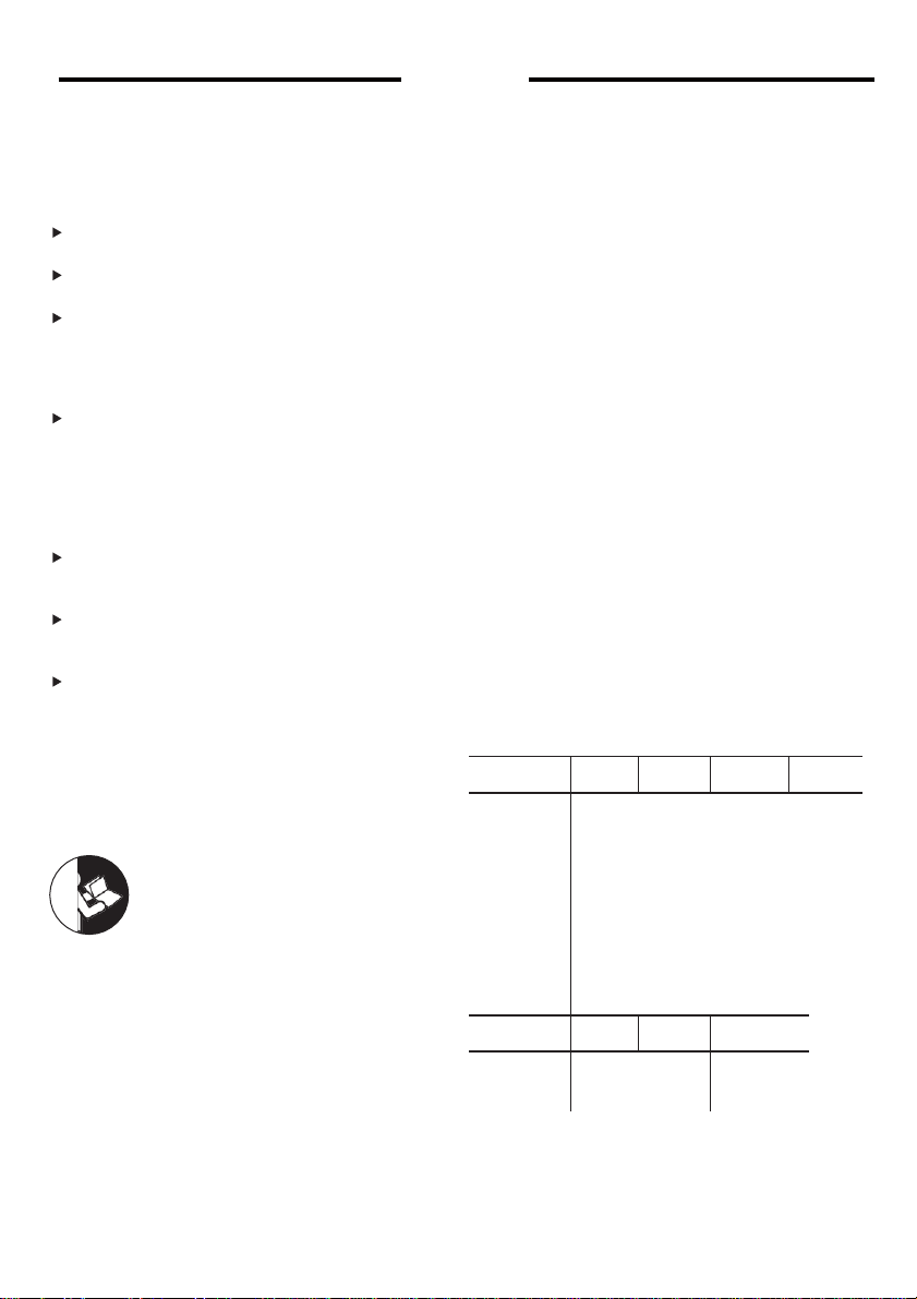
Product Features
The numbering of the product features refers to
the illustra- tion of the machine on the graphics
page.
1 Tool holder
2 Dust protection cap
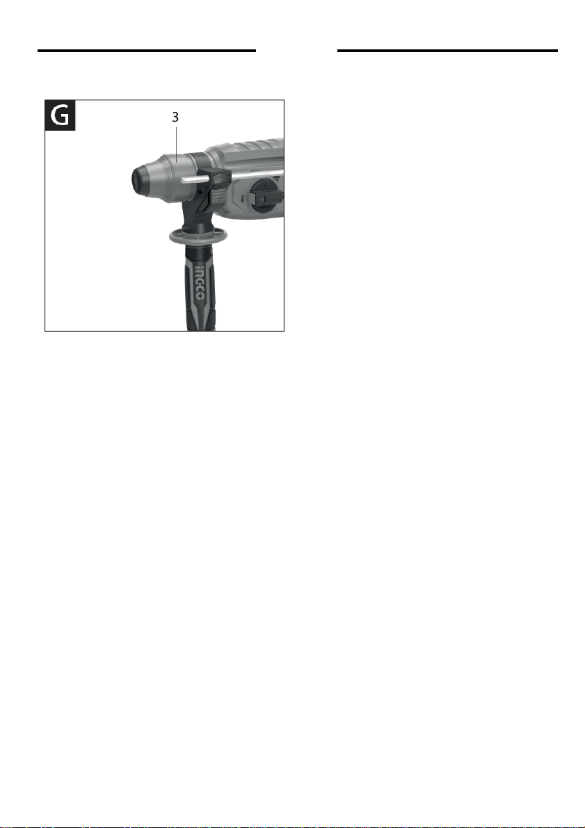
3 Locking sleeve
4 Rotational direction switch
5 Lock-on button for On/Off switch
6 On/Off switch
7 Release button for mode selector switch
8 Mode selector switch
9 Button for depth stop adjustment
10 Depth stop
11 Auxiliary handle
12 Handle
*Accessories shown or described are not part of the
standard de- livery scope of the product. A complete
overview of accessories can be found in our
accessories program.
lead to loss of control over the power tool.
Product Description and
Specifications
Read all safety warnings and all instruc-
tions.
Failure to follow the warnings and
in- structions may result in electric shock,
fire
and/or serious injury.
Intended Use
The machine is intended for hammer drilling in
concrete, brick and stone, as well as for light
chiselling work. It is also suitable for drilling
without impact in wood, metal, ceramic and
plastic. Machines with electronic control and
right/left ro- tation are also suitable for
screwdriving.
Technical Data
Model No.
RGH9028-2
RGH9028-26
(ISRAEL Plug)
RGH9028-28
(BS Plug)
RGH9028-2M
Rated voltage:
Rated input
power: No-load
speed: Impact
times: Drilling
capacity:
Concrete:
Steel:
220-
240V~50/60Hz
800W
0-
1100/min
0-
4000/min
26m
m
13m
m
Wood:
30mm
Model No.
RGH9028S-2
(SAA Plug)
RGH9028-29
(IRAM Plug)
URGH9028-2
Rated voltage:
Rated input
power: No-load
speed: Impact
times: Drilling
capacity:
Concret
e:
Steel
:
Wood:
220-240V~50/60Hz
110-120V~50/60Hz
800W
800W
0-1100/min
0-1100/min
0-4000/min
0-4000/min
26m
m
13m
m
1˝
1/2˝
30mm
1-3/16˝

11|English
Assembly
¥• Beforeanyworkonthepowertool
itself,pull
the mains plug.
Auxiliary Handle
¥• Operate your power tool only with theauxil-
iary handle 14.
Rotating the Auxiliary Handle
The auxiliary handle 14can beset toany position for a
secure and low-fatigue workingposture.
Turn thebottompartoftheauxiliary handle14incoun-
terclockwise direction and swivel the auxiliary handle
14tothedesiredposition.Thenretightenthebottom
partoftheauxiliaryhandle14byturninginclockwise
direction.
Payattentionthattheclampingbandoftheauxiliary
handleispositionedinthegroove onthehousingas
intended for.
Adjusting the Drilling Depth
Therequireddrillingdepth canbesetwiththedepth
stop 13.
Press the button for the depth stop adjustment 12and
Removing/inserting the Quick Change
Removing the Quick Change Chuck
Pullthelockringforthequickchangechunk6toward
therear,holditinthisposition andpullofftheSDS-plus
quick change chuck 2 or the quickchanpe keyless
chuck 1 toward thefront.
Afierremoving,protect thereplacement chuckagainst
contamination.
Inserting the Quick Change Chuck
Before inserting, clean the quick change chuck and
apply a light coat of grease to the shank end.
GrasptheSDS-plus quickchange chuck2orthequick
changekeylesschuck1 completely withyour hand.
Slidethe quick change chuck with aturning motion
ontothedrillchuckmountinguntiladistinctlatching
noise isheard.
Thequickchangechuckisautomaticallylocked.Check
thelockingeffectbypullingthequickchangechuck.
Changing the Tool
insertthedepthstopintotheauxiliaryhandle14.
The knurledsurface of thedepthstop13must face
downward.
Insert the SDS-plus drilling tool to the stop into the
SDS-plustoolholder3.Otherwise,themovabilityofthe
SDS-plus drilling tool can lead toincorrect adjustment
of the drilling depth.
Pulloutthedepthstopuntilthedistancebetweenthe
tip of the drill bit and the tip of the depth stop corre-
spond with the desired drillingdepth
The dust protection cap 4 largely prevents the entry of
drilling dustintothetoolholderduringoperation.When
inserting the tool, take care that the dust protection
cap 4 is notdamaged.
¥•
A damaged dust protection
cap
ahould be
changed immediately. We recommend having
thiscarriedoutbyanafter-salesservice.
Inserting SDS-plus Drilling Tools
TheSDS-plusdrillchuckallowsforsimpleandconve-
nientchangingofdrillingtoolswithouttheuseofaddi-
Selecting Drill ChucM and Tools
For hammer drilling and chiseling, SDS-plus tools are
required that areinserted in theSDS-plus drillchuck.
For drilling without impact inwood, metal, ceramic and
plasticaswellasforscrewdrivingandthreadcutting,
tools without SDS-plus are used (e.g., drills with cylin-
dricalshank).Forthesetools, akeylesschuck orakey
type drill chuck arerequired.
Note:DonotusetoolswithoutSDS-plusforhammer
drilling or chiseling! Tools without SDS-plus andtheir
drillchucksaredamagedbyhammer drilling orchiseling.
TheSDS-plusquickchangechuck2 caneasilybe
replaced against the quick change key- less chuck1
provided.
tional toole.
Insert the SDS-plus quick change chuck 2.
Clean andlightlygrease theshankendofthetool.
Insertthetoolinatwistingmannerintothetoolholder
until it latchesitself.
Check the latching by pulling the tool.
As a requirement of the system, the SDS-plus drilling
tool can move freely. This causes a certain radial run-
outatno-load,whichhasnoeffectontheaccuracyof
thedrillhole,asthedrillbitcentersitselfupondrilling.
Removing SDS-plus
Drilling Tools
Pushbackthelockingsleeve5andremovethetool.

12|English
Inserting Drilling Tools without SDS-plus
Note: Do not use tools without SDS-plus for hammer
drilling or chiseling! Tools without SDS-plus and their
drillchucksaredamagedbyhammerdrillingorchiseling.
Insert the quick change keyless chuck 1.
Firmly hold the retaining ring 6 of the quick change
chuck.Openthetoolholderbyturningthefrontsleeve
5 untilthetoolcanbe inserted.Tightlyholdtheretain-
ing ring 6 and firmly turn the front sleeve 5 in the
directionofthearrowuntiladistinctlatchingnoisecan
be heard.
Check the tight seating by pulling the tool.
Note:Ifthetoolholderwasopenedtothestop,then
thelatchingnoisepossiblymaybeheardwhileclosing
thetoolholderandthetool holder will notclose.
Inthiscase,turnthefrontsleeve 5 onceintheoppo-
site direction of the arrow. Afterwarcls, the tool holder
can be closed (tightened) apain.
Turnthemodeselectorswitch11tothe“Drilling" posi-
tion.
Removing Drilling Tools without SDS-plus
Firmly hold the retaining ring 6 of the quick change
chuck.Openthetoolholderbyturningthefrontsleeve
5 in the direction of the arrow until the tool can be
removed.
Operation
Starting Operation
•
Observecorrectmainsvoltage!Thevoltageof
thepowersourcemustagreewiththevoltage
specified onthetype plate of thepower tool.
Setting the Operating Mode
Theoperatingmodeof the power tool isselected with
the mode selector switch 11.
Note: Change the operating mode only when the
machine is switched off! Otherwise, the machine can
be damaged.
Tochange theoperating mode, push therelease but-
ton 10 and turn the mode selector switch 11 to the
requested position untilitcanbeheardtolatch.
Position for hammer drill-
ing in concrete or stone
Position for
drilling
without
impact in wood, metal,
ceramicandplasticaswellas
for screwdriving and thread
cutting
Vario-Lock position for
adjustment of the chiseling
position
Themodeselectorswitch11
doesnotlatchinthisposition.
Position for Chiseling
Reversing the Rotational Direction
Therotational directionswitch 7is usedtoreversethe
rotationaldirectionofthemachine.However,thisisnot
possible withthe On/Off switch 9actuated.
Right rotation: Turn the selector switch for drill-
ing/hammerdrilling 7onbothsides tothestopin
the positionR.
Left rotation: Turn the selector switch for drill-
ing/hammerdrilling 7onbothsides tothestopin
the position L.
Set the direction ofrotation for hammer drilling, drilling
andchiseling always to right rotation.
Switching On and Off
To start the machine, press the On/Off switch 9.
TolocktheOn/Offswitch,keepitpressedandaddi-
tionally push the lock-on button8.
Toswitchoffthemachine, releasetheOn/Offswitch
9.WhentheOn/Offswitch9islocked,pressitfirstand
then release it.
Setting the Speed/Impact Rate
Thespeed/impactrateoftheswitchedonpowertool
can bevariably adjusted, depending on howfar the
On/Off switch 9 is pressed.
Light pressure onthe On/Off switch 9 results in low
speed/impact rate. Further pressure on the switch
increases the speed/impact rate.

13|English
Maintenance and Service
Maintenance and Cleaning
Before any work on the machine itself, pull the mains
plug.
For safe and proper working,always keep the machine
and ventilation slots clean.
A damaged dust protection cap should be changed im-
mediately. We recommend having this carried out by
an after-sales service.
–Clean the tool holder
1
each time after using.
If the machine should fail despite the care taken in manufac-
turingandtestingprocedures,repairshouldbecarriedout by
anafter-salesservicecentreforourpowertools.

14|English
RGH9028-2,RGH9028-2,URGH9028-2,RGH9028-2M
RGH9028-26,RGH9028-28,RGH9028S-2,RGH9028-29
EXPLODED VIEW

15|English
SPARE PART LIST
RGH9028-2,RGH9028-2M,URGH9028-2,RGH9028-2M
RGH9028-26,RGH9028-28,RGH9028S-2,RGH9028-29
NO.
Part Description
Qty
NO.
Part Description
Qty
1
Dust Cap
1
54
O Ring
1
2
Dust Cap Washer 9.3X13X0.5
1
55
Cylinder
1
3
Snap Ring
1
56
Cylinder Pin Washer
1
4
Washer
1
57
Cylinder Pin
1
5
Snap Ring
1
58
O-Ring
1
6
Locking Sleeve
1
59
Holder Bushing
1
7
Thick Washer
1
60
Holder
1
8
Steel Ball
1
61
Press Fork
1
9
Washer
1
62
O-Ring
1
10
Spring
1
63
Bearing 609Z
1
11
Snap Ring
2
64
Bearing Press Plate
1
12
Drill Bit Cover
1
65
M4*8 Screw
2
13
Steel Ball
8
66
Gear Shaft
1
14
Keyless Chuck
1
67
Bearing 699Z
1
15
Connecting Bushing
1
68
Model Selector Fork
1
16
Chuck Adaptor
1
69
Fork Spring
1
17
Snap Ring
1
70
Needle Roller Bearing Hk0908
1
18
Snap Ring
1
71
Rocker Bearing
1
19
Ring
1
72
Needle Roller Bearing K15
1
20
Spring
1
73
33 Teeth Gear
1
21
Bushing
1
74
Spring
1
22
Chuck Sleeve
1
75
Spring Holder
1
23
St4.1*45 Self Tapping Screw
4
76
Position Washer
1
24
Torsional Spring
4
77
Rotor
1
25
Cylinder Housing
1
78
Insulation Washer
1
26
Oil Sea
1
79
Bearing 607Z
1
27
Bushing
1
80
Wind Guide
1
28
Needle Roller Bearing Hk3012
1
81
St3.7*17 Self Tapping Screw
2
29
Needle Roller Bearing Hk0709
1
82
Stator
1
30
Nine Teeth Washer
1
83
Inductor
2
31
St3.9*14 Self Tapping Screw
4
84
Bearing Bush
1
32
Flat Snap Ring
1
85
Gear Housing(Black)
1
33
Washer
4
86
Switch Contact
2
34
Spring
1
87
Carbon Brush Holder
1
35
O-Ring
1
88
Spring
2
36
Model Selector Pole
1
89
Carbon Brush
2
37
Model Selector
1
90
Stator Insert Line 120
2
38
Spring
1
91
Switch
1
39
Locking Button
1
92
Cable 2*0.75Mm
1
40
Big Gearing
1
93
Protective Sleeve Locating Sleeve
1
41
Connect Pipe
1
94
Rubber Sleeve
1
42
Pin
3
95
Press Cable Board
1
43
Clutch Disk
1
96
St4.1*16 Self Tapping Screw
5
44
Snap Ring
1
97
Back Cover(021C )
1
45
Oil Sea
1
98
Clamping Band
1
46
Thrust Ring
1
99
T Screw
1
47
Striker Shaft
1
100
Support Clamp
1
48
Striker Bushing
1
101
Locking Button Spring
1
49
O Ring
1
102
Locking Button
1
50
O-Ring
1
103
Depth Gauge
1
51
Holding Jacket
1
104
Auxiliary Handle
1
52
Snap Ring
1
105
Nut
1
53
Piston
1

This manual suits for next models
6
Table of contents
Other IN-ECO Rotary Hammer manuals

Popular Rotary Hammer manuals by other brands

Makita
Makita HR2800 instruction manual

Bosch
Bosch Professional GBH 18V-28 DC Original instructions

Makita
Makita CP100DSA instruction manual

HIKOKI
HIKOKI DH12DD Handling instructions

Hitachi
Hitachi DH 28PD Instruction manual and safety instructions

Bosch
Bosch Professional GBH 18V-45 C Original instructions


