Inca 2200 User manual

v
GarrettWade
CfJlflp1111y,
/"'
161
Ave
of
the Americas
New
York,
New
York
10013
Phone: (800) 221-2942
Fax:
(800) 566-9525
Inca Model 2200 12" Tablesaw
Siscer Tabitha Babbie invented
che
modern tablesaw, at
che
Harvard Shaker community in 1810. Imagine with what delight
che practical Shakers welcomed chis innovacion.
Nearly 2 centuries lacer, relatively
few
changes have been made in
che basic design; chere is a power source, cable and projecting
blade, and a fence. Necessicy, rime, and inventiveness have given
us precision bearings, che rile arbor, and che
mitre
guide.
In
addi-
tion
we
have superior blade and fence design, and improved safety
and sawdusc collection features. Combined, they make
che
cable-
saw che unquestioned workhorse
in
che
\Wadworkers' arsenal.
I
nca
had it's beginning over 100 years ago
as
an aluminum mold
and die maker, casting aluminum
in
precise shapes for ocher
industrial uses.
When
a handsaw manufaccurer
wcnc
ouc
of
busi-
ness leaving behind che dies for a 1
O"
handsaw, che company
was
quick ro
cake
advantage
of
the sicuacion. With all
che
expensive
dies already paid for,
it
was a simple matter ro produce the
machine, buc a risky venture into unknown selling cerricory.
The
experiment obviously paid off. And you are the benefaccor
of
over
60
years
of
cool
making experience. Originally engineered in
Switzerland,
che
Inca line is now produced
in
France and cakes
advantage
of
che common marker experience.
We thank
you
for buying che Inca Model
2200
12"Tablesaw.
We
believe you've made a wise decision.
The
design process combined
the
inpuc
of
Swiss engineers (renowned for their precision clock-
making), designers and woodworkers like you (both amateurand
professional)
co
create a user-friendly precision machine.
Designed for a lifecime
of
service, your new Inca Model 2200 12"
Table Saw, includes che
lacesc
assembly
of
advanced features.
Although you may be very experienced
in
using and setting
up
machinery, please cake
che
time
ro read
the
manual.
The
mosc
experienced woodworker will benefit by seeing old information in
a new
way.
While
che
Inca is similar ro ocher cable saws in use
and controls, chere are some things you may find new and useful
co
know before you
scare
ro work.
Firsc: Check ouc your new saw. Machines are generally shipped by
truck
.
When
che driver delivered your saw, you probably signed a
bill
of
lading acknowledging receipt.
Unpack and inspect your saw promptly.
If
anyching has been
dam-
aged in
shipment
it
is your responsibility
co
file a "concealed dam-
age claim".
Afcer che claim has been filed an inspecror will check
che
damage,
so you muse keep che shipping materials.
You
may make a "concealed damage claim" even
if
there
was
no sign
of
damage ro the box
ac
the cime
of
delivery,
bur,
you muse
do
ic
prompcly. After che inspeccion,
we
will help you file a claim.
Moving
through
a
narrow
doorway:
Remove the crank handle
of
che angle adjustment wheel. Loosen che set screw in the lock collar
of
the
worm on che angle adjuscment mechanism. Work
che
rod
ouc
of
che machine.
Reverse accions ro reinstall.
Page
1
Where
To
Find
It
Accessories
17
Angle Scale
13
Angle Stops
15
Blades
17
Belt Tension
11
Crosscutting 9
Fence 4
Guard and splitter
14
Insert Places
14
Leveling Machine 3
Maintenance
15
Mitre Guide 5
Mascerfence, align 4
Parallel
12
Rail Lock Knob 4
Rear Clamp
15
Ripping 7
Scale, measuring 6
Specifications
17
Trunnions
13
legs, tables, blades, etc.
stop limits and scale
trunnion limits
sizes and teeth configuration
drive belt adjustment
mitre guides and sleds
uses and functions
2 kinds
of
guards
at
the blade
feet
lubrication
square
co
the blade
blade and fence
prevent rail from moving
on fence
How-to and why
front rail scale
mocor, speed, amps,
ecc.
keep clean, adjusting
SOME SUGGESTIONS FOR SAFE
WORK
HABITS.
DON'T
RUSH! The
wood
has
been waiting for years
co
be your
cable
or chair.
A
few
more minutes doing
it
right won't hurt.
NO
LOOSE
CLOTHING.
It
will gee caught in things or places which will lead
to
disaster. Shirt sleeves will catch blades or bits. Ties will be sucked into the
vortex.
DO
NOT
SMOKE while operating machinery.
DO
NOT
DRINK
and operate machinery.
DO
NOT
WORK
WHEN
YOU ARE TIRED
OR
DISTRACTED.
The number one cause
of
accidents
is
lack ofconcentration. you cannot con-
centrate when you are tired.
IF
IT LOOKS
AND
FEELS
RISKY, IT
IS.
Seek help; ask someone with more
experience.
Remember, you have spent
years
growing useful parts
of
your anatomy.
Don't
cue
pieces
of
it
off.
Fingers have many ocher uses.
The
exploded
view ofmachine pares attached
is
of
previous Inca model
2100SE. Model 2200 has the following changes:
1. New model
has
single drive belt.
2. Table miter
sloes
are now T-slocs, %"x
W'
3. There
is
no
longer a cucouc
in
the cabinet side
for
the mortise attachment.
4.
Tool
kit
is
not
as
shown on the exploded view.
All ocher parts and part numbers arc generally unchanged.
Page
2

Quick
Start
Procedure
If
you are already familiar with table saws, follow this procedure
for setting up your saw quickly.
Locate all the unattached parts
of
the saw, some
of
which are
shipped inside the saw body
These are the standard parts shipped with your saw:
2 Crank wheels with handles
Blade guard and splitter
Masterfence and Extrusion
Mitre Guide
The
Tool
Kit
contains:
Wrench
Blade
spacers
~·
r
Allen
Wrench
Arbor
locking
bar
QuickStart
l.
CHECK
THAT
THE
SHIPPING
BRACE
IS
REMOVED: A mecal
pedestal support under
che
mocor, held by one bole. Do
noc
operate
crank wheels with
ic
in place.
2. Mount
che
handles on che wheels: chey use an allen key
or
a nuc on
the handle shaft.
3. Mount wheels
co
shafts: Larger handle on front
co
adjust height.
Note:
Keyways
must
line
up.
4. Mount rails: Loosen all four scar knobs under cable
cop
Mount
che
MascerFence: Make sure che rear clamp
is
facing the rear.
S. Check: fence square
co
che blade?
6. Mount extrusion: Slides onto che bole heads on
che
fence. Accicude
is your choice.
Levelling
the
machine.
Each
of
che
four
feec
is accached
co
che
frame
with
cwo
socket head screws.
They pass through
che
sloes in
che
frame
so
feet may
be
raised or lowered.
If
you use a three-wheeled rolling support (such
as
HTC's) you can skip
chis seep.
1.
Find
che
foot
noc
couching
che
floor.
2. Loosen che
cwo
mounting
screws and gently lower
ic
until it and all
ocher feet are couching che floor. There
is
also a floor
mounting
bole
hole which you may use
co
bole your saw
co
che
floor. Before doing
chac,
run che machine
co
discover
if
che floor
ac
chac
point
is
"live".
Some floors have areas more prone
co
vibration chan ochers. Many peo-
ple also puc chin rubber pads under che feet
co
further dampen vibra-
tion.
(If
you have
bought
che
HTC
roller base, che leveling
is
auto-
matic, and nothing need be done.)
Page
3
Complete Assembly Details
1.
Attach
the
handles
co
the rims
of
the wheels.
2.
Put
the larger
of
the
two
crank wheels on the height adjustment rod at
the front
of
the machine.
Noce: The key in the shaft muse mate wich the keyway in
che
crank
wheel hub.
3. Puc the smaller wheel on the
side rod.
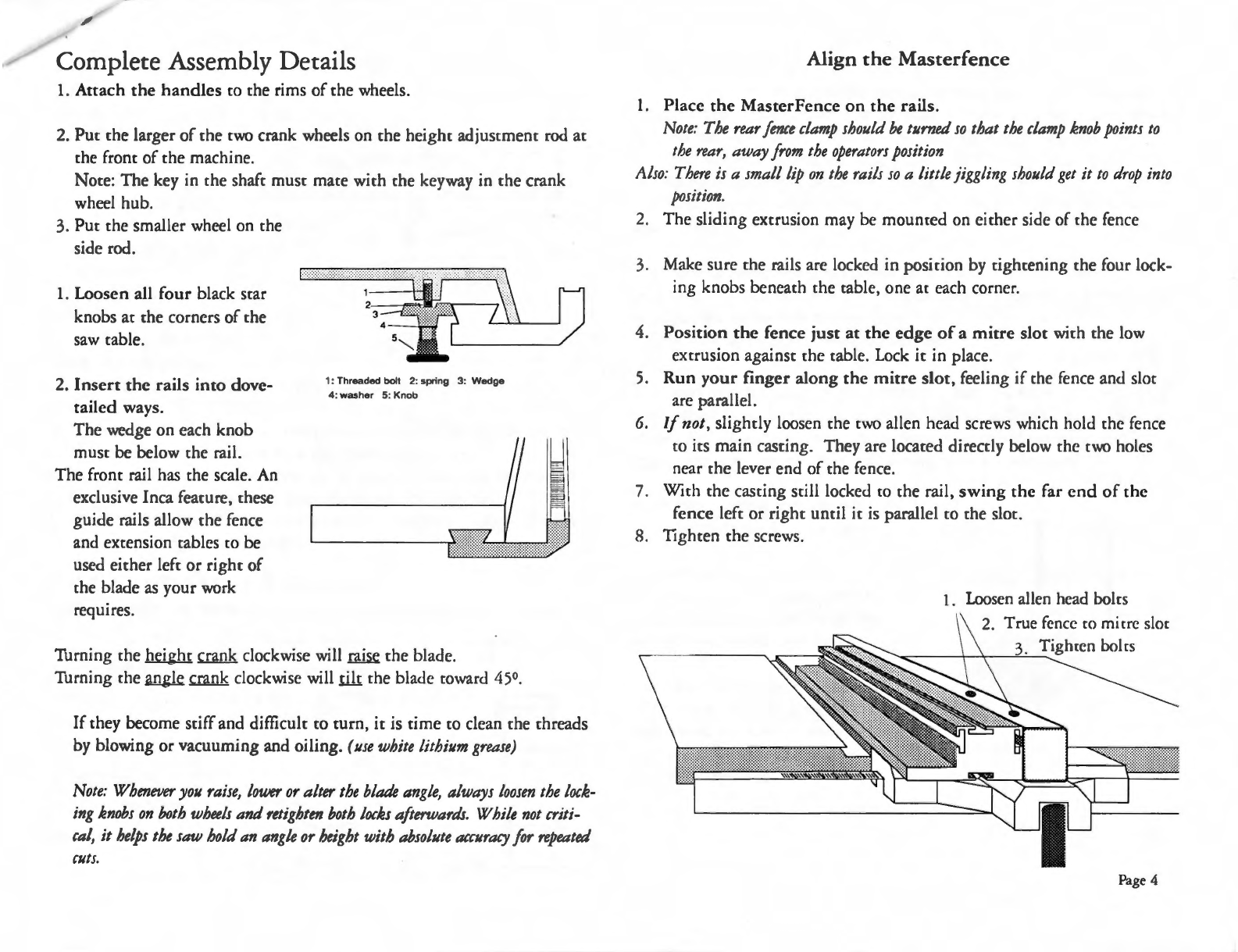
1.
Loosen all
four
black
scar
knobs
at
che
corners
of
che
saw
cable.
2.
Insert
the
rails
into
dove-
tailed
ways.
The wedge on each knob
muse
be
below
che
rail.
The front rail has
che
scale.
An
exclusive Inca feacure,
chese
guide rails allow the fence
and extension cables
co
be
used either left
or
right
of
che
blade
as
your work
requires.
1: Threaded bolt 2: spring 3: Wedge
4: washer 5: Knob
Turning
che
height crank clockwise will
raise
the blade.
Turning the
.angle
.c..mnk
clockwise will
I.ili
che
blade coward
450.
If
they become sciffand difficulc
co
turn,
ic
is time
co
clean
che
threads
by blowing or vacuuming and oiling.
(use
white
lithium
grease)
Note:
Whenever
you
raiJe,
tower
or
alter
the
blade
angle,
alwayJ
tooJen
the
tock-
ing
knobs
on
both
wheels
and
retighten
both
tocks
afterwards.
White
not
criti-
cal,
it
helps
the
saw
hold
an
angle
or
height
with
absolute
accuracy
for
repeated
cuts.
Align
the
Masterfence
I.
Place
the
MasterFence
on
the
rails.
Note:
The
rear
fence
clamp
should
be
turned
so
that
the
clamp
knob
points
to
the
rear,
away
from
the
operators
position
Also:
There
is
a small
tip
on
the
rails
so
a little jiggling
should
get
it
to
drop
into
position.
2.
The sliding extrusion may be mounted on either side of
che
fence
3. Make sure
che
rails are locked in posicion
by
cighcening the four lock-
ing knobs beneath
che
cable, one at each corner.
4.
Position
the
fence
just
at
the
edge
of
a
mitre
slot
wich
che
low
excrusion against the table. Lock
it
in place.
5.
Run
your
finger
along
the
mitre
slot,
feeling
if
che
fence and
sloe
are parallel.
6.
If
not, slightly loosen
che
cwo
allen head screws which hold
che
fence
co
its main casting. They are locaced directly below the two holes
near the lever end
of
the fence.
7. With the casting still locked
co
the rail,
swing
the
far
end
of
the
fence left
or
right until
it
is
parallel
co
che
slot.
8. Tighten the screws.
1.
Loosen
allen head
boles
True
fence
co
mitre slot
_-.......~-
-+--i.:
-
~3""-'._T...:ighrcn
bol
rs
Page4
/
Fence
Lock
1.
Lock
che
fence in place, only
ac
che fronc, by
pushing
down che locking
lever.
2.
Wich your hand near
che fronc rail,
cry
co
move
che
fence.
If
ic moves, release che
lever and readjusc che
cighcness
of
che
lock-
ing lever.
3. Turn che fence over
and you will be able
co
see
che mechanism.
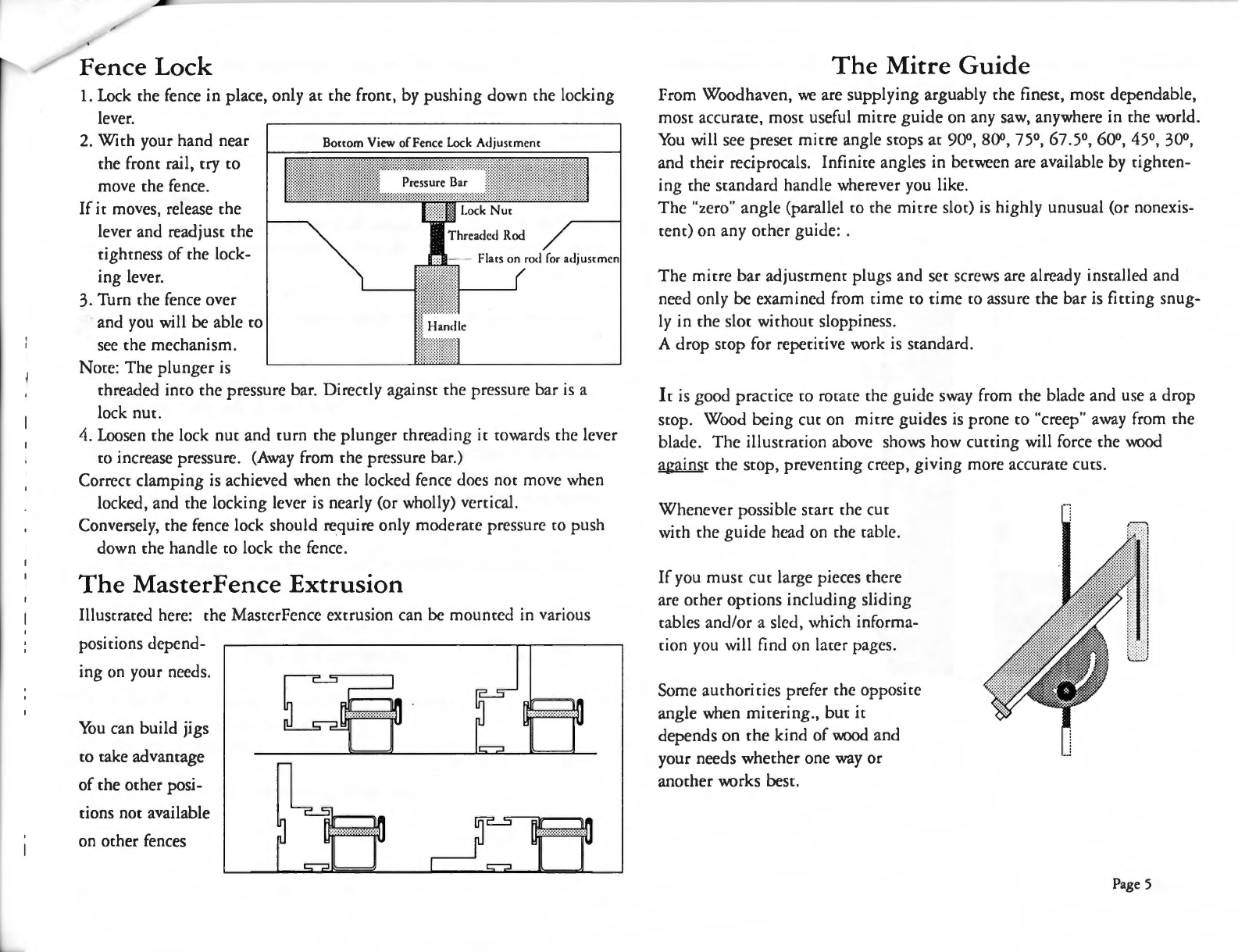
Nore:
The
plunger
is
Bonom
View
offence
Lock
Adjuscmem
chrcadcd inco chc pressure bar. Dircccly againsc chc pressure bar is a
lock nuc.
4. Loosen chc lock nuc and curn che plunger threading
ic
cowards chc lever
co
increase pressure.
(Away
from che pressure bar.)
Correcr clamping is achieved when
chc
locked fence docs nor move when
locked, and the locking lever is nearly (or wholly) vcrcical.
Conversely, che fence lock should require only modcracc pressure
co
push
down che handle
co
lock
che
fence.
The
MasterFence Extrusion
Illuscraccd here: che MasccrFcncc excrusion can be mounccd in various
positions depend-
ing on your needs.
You
can build jigs
co
cake advancage
of
che ocher posi-
tions nor available
on ocher fences
The
Mitre
Guide
From Woodhaven,
we
are supplying arguably che finesc, mosc dependable,
mosc accurace, mosc useful micrc
guide
on any saw, anywhere in che world.
You
will sec presec mi
ere
angle scops
ac
900, 800, 75°, 67.5°, 60°, 45°, 30°,
and chcir reciprocals. Infinice angles in bccwecn are available by cighcen-
ing che scandard handle wherever you like.
The
"zero" angle (parallel
co
che micre sloe)
is
highly unusual (or noncxis-
cenc)
on
any ocher guide: .
The
mi
ere
bar
adjuscmenc plugs and
sec
screws arc already installed and
need only be examined from rime
co
rime
co
assure che bar is ficcing snug-
ly in che sloe wichouc sloppiness.
A drop scop for repecicive work
is
scandard.
le is good praccice
co
rocace
chc
guide
sway from che blade and use a drop
scop. Wood being cue on micrc guides
is
prone
co
"creep" away from the
blade.
The
illuscracion above shows how cuccing will force chc
wood
against chc scop, prevcncing creep,
giving
more accuracc cues.
Whenever possible
scare
che cue
wich
chc
guide
head on
che
cable.
If
you muse cue large pieces there
arc ocher
options
including sliding
cables and/or a sled, which informa-
cion you will find on lacer pages.
Some auchoricics prefer
chc
opposicc
angle when mitering., bur
ic
depends on chc kind
of
wood
and
your needs whecher one way
or
anocher works besc.
Page
5

Adjusting
the
Rails
and
the
Front
Measuring
Scale
The
easy
adjustment
of
the rails and the measuring system
of
your new
INCA Model
2200
is the key
co
making your work faster, easier and more
accurate.
·
You
can set the rails and scale
so
chat you can always directly read
che
dis-
tance from fence
to
blade regardless
of
whether you choose
to
use a wooden
auxiliary fence or choose
to
measure from
che
left, right or center
of
the
blade.
The system also allows you
to
make rips
co
the maximum capacity left or
right
of
the blade
The
adjustments here arc
to
set che fence and scale for ripping with the
fence on the
right
side
of
the blade.
There are
nm
windows on the fence, and only one is exposed at a time.
The one
co
the right
of
the fence is visible when the extrusion is on the
left side
of
the fence.
The
fence extrusion should always cover the window
you
aren't using.
l.
Bring the fence extrusion
right
up
co
the blade,
just couching buc
noc
pressing, and lock
ic
in place.
Note:
(If
you
will
be
using
a
wood
auxiliary
fence,
it
should
be
on
now.)
2.
Slide the scale alone along the cop
of
che front rail until the arrow in
the window is
pointing
ac
the
"O".
You
are "zero'ed in".
3. Move the rear rail
co
complement the front rail.
(When
you
change
rail
position
or
move
the
fence
to
the
other
side
of
the
blade
you
will
repeat
this
exercise
to
make
the
scak
accurate.)
As
you can see, the scale can
be
readily aligned with any fence or auxil-
iary fence you choose.
Also you can align
it
co
read from either side,
or
center,
of
the blade or
cuccer.
Page
6

Part
3
Ripping
technique
is important in order
co
cut straight and true
It
may
seem
obvious
but
as
with all
saw
cuts, you
must
prepare
i!lll:JiJJ!
.li·:1:=J1'·1=1:::11:11:::111
1
;11ttlllll
f k
For the smoothest cut,
we
recom-
mend you set the blade height
so
that the gullet between teeth
is
level with the mp
of
the
wood
being cue.
If
you raise the blade mo high, the
teeth are exiting the wood at a
high angle which causes tear-out.
1.
Make sure the
wood
is level on the table
as
the
wood
approaches the
blade
Cautions:
If
the
wood
is
not
flat
it
can
cause
the
blade
to
suddenly
catch
the
wood
causing
sudden
shock
to
teeth
or
wood
Both
teeth
and
wood
can
shatter
with
unpleasant
results.
2. Support the work after
it
passes the blade
co
avoid losing control
of
the end
of
the cut.
Note:
A
catch
table
behind
your
saw
or
a
set
of
rollers
will
help
to
avoid ruining
valuable
work
and
help
prevent
injury.
3.
As
you push
wood
imo
the blade, be aware of the direction that you
are pushing the
wood.
As
the illustration shows, feeding the
wood
with some pressure
towards
the
fence insures that you will not inadvertently skew the
cut.
4. Your
Right
hand
pushes forward while your left hand keeps the
wood
tight
against the fence (as illustrated).
Pushing IQQ
fufil.
with
~
chick hardwoods can strain the momr which
will aucomatically
cue
off
if
ic
over-
heats.
Pushing too slow or srnpping risks:
l.
burning
the
wood
2. kickback.
Try for a consistent speed and effort.
Keep you hands
and
clothes
away
from the blade.
If
you
must
make
cuts near the blade, USE
THE
PUSH
STICK.
Working Blade Height: Should show only a few teeth above the work.
YES!
Page 7
Ripping: general practice
Traditionally,
cutting
is
done with the fence on the right
side, so the text and illustrations show
that
position.
If
you prefer to work with the fence on the left,
reverse the arrangement.
Never stand in line with the blade. Stand
to
the side
of
the blade opposite the fence. Push the work along
the fence applying side and forward pressure, holding
the workpiece with both hands initially. Apply for-
ward pressure with right hand and sideways pressure
(towards the fence) with your left hand.
Maintain a balanced stance
so
your feet won't slip, pitching
you into the blade.
As
you near completion, continue to push past the blade
with your
right
hand and move your left hand out
of
the
way.
On
narrow cuts,
get
in the habit
of
hook-
ing one or two fingers
of
your
right
hand over the
fence. Do not lean over the blade.
Your left hand should nor push the waste past the blade.
That
can cause pinch and kickback. A carch table at
the back
of
the saw will support long boards when
ripping and crosscutting large panes so they won't fall
off the back
of
the saw and damage your work or cre-
ate
an
unsafe condition.
Crosscutting:
Onec your boards are
cut
so
there are two parallel long
sides and two flat faces, you
must
usually
cut
one end
square and true and the other end to length. Start by
using the
mitre
guide
for
small pieces, or a cut-off
sled riding in the mitre slot.
The
sled can be open
ended over one mitre slot or large, covering the entire
table. Sleds are
far
more accurate then mitre guides
because the fence are large and will not allow the
work
ro
twist or pivot. Accuracy
is
assured
if
you
rake the
time
to
build
an
accurate sled. Make several
sleds ar once
to
do 45°
as
well
as
90° cuts
Page 8

Crosscutting
Techniques
The
Mitre
Guide
is
intended for relacively small work.
Absenc a posicive locking device holding che procraccor head in position,
large and/or heavy work may cause che head
co
cwisc.
In addicion
co
a scop
on
che
fence, many woodworkers
glue sandpaper
co
che face
of
che
fence
co
help avoid
creep.
Whenever possible
scare
che
cue
wich che
guide
head
on
che
cable.
If
you muse
cue
large pieces
chere are ocher options
including sliding cables
and a sled, illuscraced
here. t
1 a a t
1
The
sled
size
is
relevanc
co
che work you are doing. Keep in mind you
will
be
able
co
crosscut
as
well
as
micre
wich
chis device depending on
whac
auxiliary fences you incorporate.
I.
Lay
2 pieces
of
hardwood W' x %" x 24" in
che
mi
ere
sloes. They should
fie
quice well.
2. Raise chem slightly above che cable surface by puccing dimes under
chem fronc and back.
3. Spread a running bead
of
yellow
glue
along che
cop
of
each one.
4. Carefully lay a piece
of
14"
ply on
cop
of
chem
as
square
as
you can. (le
isn'c critical).
Note:
You
may
use
any kind
of
ply and
any
thickness.
We
chose
!1.4"
for
its
light
weight.
4. Weight che ply wich books or bricks or whacever.
Lee
dry for 2 hours or
more.
5.
Accach
a 2 x 4
on
edge
co
che
from and back by screwing
up
through
che ply inco che 2x. Be
as
square
as
you can. Use only one screw in each
end. Ic's a cemporary hold. Make sure
che
sled slides in che cracks.
1.
Wich che Blade lowered, turn on che saw and raise
che
blade
up
through
che sled. Don'c
lee
che sled move.
2. Wich che blade abouc
1"
above
che
cable, move
che
sled back
~nd
forth
elongacing che kerf.
Do
noc
cue chrough che 2 x 4's.
3. Used a square againsc che sloe you've cue
co
make che 2x's perfectly
perpendicular.
3. Afcer assuring perpendicularity, accach che 2 x 'i's wich more screws and
cue
through
chem.
You
now have a sliding cable which can give you
very accurace crosscucs.
Page
9

Reproducing
an
exact
cut
width.
Position the piece
to
be reproduced against the fence and
leave
some space next to the blade. 1" would be ade-
quate. Using the piece to be copied
as
a fence, cut a
piece
of
scrap. Do not move the fence.
The scrap will replace the piece and now any other piece
run through agaiinst the scrap will be aucomaticall
the same size
as
the original piece.
It
is
repeatable and requires no measurement,
no
set-up.
Steel die-makers use this technique to saw blockes
of
ply-
wood
to
precise dimensions.
Page
10

Aligning
and
Tuning
Best results always come from
machines
which are correctly
aligned
and
tuned
.
These
are
the
important
areas on which
we
recommend
periodic
checking
.
A.
Saw
blade
and
fence
parallel
to
the
mitre
guide
slots
B.
Blade
angle
stops
at
45°
and
90°
C.
Blade
angle
scale
D.
Splitter
and
guard
E.
Table
insert
plate
Alchough chese areas are aligned
ac
rhe facrory, mi
sa
lignmenc may occur
during
shipments,
and/or
afcer some period
of
use.
You
don'c need expensive cools
co
align and resc, buc you will need a good
cry
or
combination
square.
A good
cry
square wich a
3"-6"
blade will work nicely.
Test
the
square
on che oucside firsc. Some carpenters squares are
noc
accurate boch inside and outside.
Note:
All
adjustments
should he
made
with
the
saw
unplugged
for
safety.
DO
NOT
WORK
WHILE
:
A.
TIRED
B.
DRINKING
ANY
ALCOHOL
C.
DISTRACTED
D.
WEARING
LOOSE
CLOTHING
OR
TIES
DO
NOT
WORK
WITH:
A.
SAWDUST
ON
THE
FLOOR
B. LOOSE ELECTRICAL
CONNECTIONS
C.
LOOSE
WIRES
ON
THE
FLOOR
Belt
Tension
and
con
di
ti
on
The
drive belc has a break-in period. Afcer some hours
of
use
it
may loosen
and need
co
be censioned
in
order
co
gee full power from rhe mocor
wichour
slipping
.
1.
Unplug
the saw.
2. Tilcing che arbor for easier access.
3. Loosen rhe four boles which hold
the
mocor in place.
4.
Tighren
rhe sockec head screws in
the
ends
of
che tension bracket even-
ly
,
going
from one screw
co
che ocher,
making
only small
(Ya
turn)
adjusrmencs.
5.
When
you feel you have achieved correcc tension,
righten
the
four boles
char hold che mocor in place.
6.
Rorace che
blade
by hand
co
make sure the belc
is
nor
rubbing
or scrap-
tng.
7. Reconnect
the
power
and jog che
machine
on (on
and
off
quickly)
co
make sure chc blade
is
curning
in chc
ri
g
hc
direccion.
Tensioning screws
/
'\
-
/
"'
-
~
"'
\
I
IJ
......
Page
11

~
Disconnect
the
Power!
A.
The
saw blade and fence
must
be parallel
ro
the
mitre
guide
slots.
PINCHING
HERE
WILL
LIFT
WOOD
AND
THROW
IT
BACK
TOWARDS
OPERATOR
BLADE
ANGLED
TO
LEFT
WJLL
PULL
WOOOD
AW
AY
FROM
FENCE
For any
saw
co
cue
we
ll
and accuracely
ic
is
imporca
nc
ch
ac
chc
blade
be
parallel
co
chc
micrc s
loes
and
chc
fence.
The resulcs of misalignmenc are here illuscraced
Because
chc
micre
sloes
a
re
noc
movable, all chings a
rc
aligned
co
chem.
Wi
ch
che
blade a
nd
che
fence parallel
co
chc
mi
ere
sloes, ic follows
chac
chc
blade and fence arc parallel
co
ea
ch
ocher.
1.
Raise
the
blade
co
maximum height.
2.
Lay
a combinacion square (or a dcpch gauge) against
che che
mi
ere
sloe
so
chat
che
blade
is
directed coward
che
blade.
Note
: The
body
of
the
square
should
be
snug
to
the
lip
of
th
e
slot.
3.
Rocace
che
blade
wi
ch
chc
cry
square
bl
ade close
co
che
saw
blade
co
deccrmine whccher
che
blade wobbles or spins fairly
cruc.
If
fairly cruc, pick one
cooch
.
4. Mark
ch
ac
cooch
of
chc
saw
blade and
jusc
couch
chc
cry
squa
re
bl
ade
co
chac
cooch
as
ic
is
jusc
emerging from
chc
cable.
5.
Rocacc
chc
sa
w blade forward
uncil
chc
cooch
is
almosc
di
sa
p-
pearing. Measure again.
Not
e:
Do
not
adjust
th
esquare.
In
eac
h
case
the
try
squ
are
or
de
pth
ga
u
ge
must not press
aga
inst t
he
saw
blad
e.
ju
st a bare to
uch
.
If
che
square
pushes or docs
noc
cou
ch
chc
blade in
chc
second
posicion,
chc
saw
bl
ade muse
be
re-alig
ned
co
chc
micrc
sloes.
Page
12

~
·
Realign the
Trunnions
and Saw blade
The
Saw blade rorares
on
rhe
arbor
which
runs
rhrough
bearings,
which
are
held
by
the
trunnions.
The
trunnions
can
be
moved
laterally by
loosening
the
four alien head
bolts
ar
the
back
of
rhe saw.
Access
bolts
rhrough
rhe
four
openings
cut
in
the
ourer
cabinet.
1. Loosen chem
slightly.
\'(!
arning: (DO
NOT
REMOVE)
Use a wood bar 10 gently lap 1runnion
lefl or right
al
this poinl
2.
Move
the
trunnion
left
or
righr
as
appropriare
.
3.
Test
rhe
alignment
using
the
technique
already described
on
the
prcvi-
ous
page
4.
When
the
blade
is
parallel,
tighten
the
four boles.
Note
: The tightening
action
sometimes
causes
the
trunnion
to
move
slightly.
Test
agarn.
B. Blade
Angle
Stops
at
45°
and 90°
On
the
underside
of
the
cable
on
each
side
of
the
front
trunnion
arc scops
co
set
the
saw
angle
at
45°
and
90°.
The
scop is a socket head screw
and
lock
nut
secured
against
the
table
mp
casting.
Although
cops are faccory set,
make
it
a
habit
co
examine
your
machine
often
.
The
90° scop is accessible
through
the
blade
opening.
Easier access
when
che
arbor
is
tilted
co
about
25°
and
lowered
all
rhe
way.
The
45° scop is located
on
the
opposite
side
of
the
trunnion,
accessible
through
the
access door.
Check
that
chips
or
dirt
do
not
interfere
with
the
acrion.
C.
Adjust
the
Blade
Angle
Scale
With
the
arbor
at
90°,
The
red
arrow
should
point
co
0°.
If
not:
1. loosen
the
screws
that
hold
the
scale
2.
shift
the
scale
under
che
arrow
so ir
poinrs
co
90°.
Note:
The
scale
is
marked in
!12°
increm
e
nts
.
The
scale
can
be
read
to
increments
as
fine
as
!16°
(I0
minut
es
of
arc)
Observe
rhe
shoulders
on
each
side
of
rhe
red poinrer.
As
an
example
sec
any
intermcdi-
are
angle.
For inscance: 22°.
Slowly increase
the
angle.
When
the
right
shoulder
couches
the
next
available
mark,
you
have reached
22!.1,0,
or
22°,JO'
Continue
rnrning
and
when che
lefc
shoulder
reaches a
mark,
you will
be
at
22
2
/<,0,
or
22°,20'.
The
next
mark
will couch rhe red
arrow,
and
wi
II
be
wi
II be
22%
0 (20Y2°),
or
22°,30'
Not
illuscraced
bur
conrinuing,
right
shoulder
will
show
22o/dl
(20¥1°)
Then
left
shoulder
ar
22
~
0
,
and
finally
back
co
rhe
next
mark
at
the
arrow
for 23°.
Page
13

D.
Splitter and Guard
Your
Inca
2200
comes
with
a
splitter
in
place.
le is che mecal fin
mounced
behind
the
blade
and
adjuscable so chac
ic
will noc incerfere
wich any cuccing operacion.
Ofcen, while
ripping,
a board will cry
co
close che cue jusc
made
.
It
can
pinch
the
blade
catching
the
cccch
emerging
from
the
cable and life and
kick
back
the
wood coward
the
opcracor.
This
"
kickback"
can spoil a
good
cue
and
scare you
as
well.
Make
sure
the
splicccr is exactly lined
up
with
the
blade
and docs
noc
lean
co
one
side.
It
is
the
correcc thickness for a
kcrf
(saw cue)
of
w:
and
should
noc
affccc
the
wood which has
just
been cue except
under
the
pinching
conditions
above.
Use
the
splitter
and avoid
problems
.
Position
the
splicccr no
more
than
Ya"
behind
and W' below
the
blade
height.
To
use
the
Euro
safety
guard,
you muse replace
the
scandard
splitter
with
the
one packaged wich chc
guard.
Lock inco
position
inco
the
cop
of
rhc
arbor
casting,
with
rwo socket
hca<.J
screws
These
concrol
the
118
~
~~rirr:::.ighc
position
of
chc (
~~~/
·
':/'
',
A large bole
holds
rhe
splitter
co
i
cs
brackcc
and,
loosened,
allows rhc
splitter
ro
move
up,
down,
forward and
back.
The
guard
mouncs on cop
of
rhc spliccer
with
rhe
attached
lever bole. Back
out
the
screw and
re-tight-
en
through
the
splitter.
(NOTE:
the
splitter
is
thin
steel;
if
it
becomes
bent
you
can
bend
it
back
into
correct
position
.)
E.
Table Insert
Plate
The
Table Inserc Place
as
ic
comes from che faccory, should be exactly level
with
the
cop.
Unscrew
chc franc screw and life
up
the
franc
end
of
chc place and
pull
coward you.
The
rear cab will come
out
from
under
the
cable cop.
Inscallacion is
the
reverse
procedure.
There
are 8
sec
screws on
the
boccom
of
the
place
co
assist leveling and
f1arncss. Screwing chem in
or
out
will affect
the
level
ac
chat
position.
The
set screw in
the
cab
ac
the
rear
end
of
rhc place
applies
tension
on
the
place
co
minimize
vibration.
I . Back
off
chc
sec
screw in chc rear cab
and
sec
rhc place in
the
opcning.
2.
Adjust
the
ocher screws uncil
the
place lies
f1ac
and
even
with
the
cable
su rfacc.
3. Raise
the
sec
screw in chc cab uncil,
when
the
place is inserced,
the
fronc
end
should
rise above chc cable surface
about
Ya'';
then
press
down
and
righten
rhe
fronc
locking
screw.
Optional
Insert
Plates.
We offer a special
blank
inserc place for zero
clearance
or
for special
cutters
or
narrow
blades.
While
you may
make
your
own
wooden insercs,
we
recommend
Inca places which offer
better
fir
and
f1acness.
There
are also wide
slot
inscrc places for
dadoing
and
moulding
heads.
To
cut
a
slot
in
the
blank
plate:
Lower
the
blade all
the
way, inscall che
blank
inserc, and wich rhe
machine
running,
raise che blade
chrough
rhc
place.
file
chc edges smooch.
Carbide
cccch will
not
be
harmed
by
the
special sofc
aluminum
of
the
place.
(Do
not
use
standard
sreel blades
co
cut
the
sloe.)
Page
14

~
Good
Maintenance
is
very
important.
Jc
is
che key elemenc
which will keep your Inca saw
running
crouble-free for a lifetime.
Use
a non-silicone wax on che cable surface, where wood and mecal come
rogecher. Silicones can incerfere wich wood finishes.
Do
nor use.!! floor wax.
They
concain anci-slip ingrediencs which negaces
che purpose.
Use a whice lichium grease for
the
metal
co
mecal or
plastic
co
metal con-
cacc.
Duse off, blow off and vacu
um
every day
or
week,
depending
on frequency
of
use, all chc slides
and
incernal screws
and
slides.
The
Rear
Clamp
on chc back
of
che fence is nor necessary for day-ro-
day
operations
.
Yc>u
may leave
it
loose. Use
it
when you have a long run
of
repeated
ripping
wich heavy scock.
Or
when you a
rc
u
si
ng
a hold-
down
which exerts
downw
ard pressure
on
chc work, che
clamp
will pre-
venc
the
rear
of
the
fence from
rising
.
Dust
collection
is assisted by che aerodynamically
designed
blade
enclosure which efficiently
directs
dust
co
the
4"
exhaust
port.
We
strongly
recommend
you
connect
a
proper
dusc colleccion syscem.
The
dust
collecror
should
be raced
ac
595
CFM
or better. Duse collec-
tion
keeps
the
moving
pares csean and
working
smoochly.
Blade
Elevation
Despite
che use
of
a
dust
collcccor, wood resin will
eventually
cling
co
incernal pares. Week resin dries
co
a ha
rd
metallic
skin
and
incerferes with
moving
pares. Blade elevation will begin
co
feel sticky
and
difficult
as
che carriage moves
along
the
vercical slides
fore
and
aft
of
che blade.
Blade
Tilt:
The
saw
blade
carriage tiles
by
sliding
through
curved sloes
in
trunnion
places
at
the
fronc
and
rear
of
che saw incerior.
Keep
these
sloes clean.
Troubleshooting
Machine
will
not
start
Press reset buccon
on
switch
box.
With
power
disconnected,
check
wiring in
plug,
box
and
switch.
Concacc eleccrician for concinuicy resc
co
eliminate
all possible
electri-
cal
problems
before conca
cci
ng
dealer.
Machine
starts
but
shuts
off
immediately
If
circuit
breaker
trips
in power
panel,
it
may be char
wiring
is not
heavy
enough
co
ha
ndle
load
or
chat breaker
or
fuse
is
coo small for
load.
With
power
disconnected
, does blade
turn
by
hand?
Concacc
electrician.
Machine
runs
but
blade
scops
or
stalls
when
cutting
With
power
disconnccced, does che blade
turn
by
hand
? Is
the
arbor
nuc secure? Is che belc
ci
ghc?
\X-'ood
scops
at
back
of
blade
It
may be
hitting
che splicccr.
Make
sure
splitter
is even
with
blade
\Vood
binds
between
blade
and
fence,
burning
or
pulls
away
from
fence
Fence is
not
parallel
wi
ch
blade.
\Vood
feeds
very
slowly
and
burns
badly
I.
Blade is installed
backwards,
or
motor
is
running
in reverse.
or
2.
Wcx>d
is
pinched
between
blade and fence
..
Page
15

To
Tighcen che Scale:
IF
che scale moves coo easily
you may cighcen che
springs
.
Expose chem by
sliding
che
scale ouc
of
che wa
y.
Inserc a
flac
bladed screwdriver
under
the
spring
and bend
the
spring
down
over it
co
increase
the
bow.
Increase the
bow
in small
increments
lest
the
scale
become
s
co
difficult
co
move.
Miscellaneous
Information
Change
the Blade
1.
Inserc
the
plain
bar
into
the
hole in
the
right
hand
mitre
slot.
There
is a
corresponding
hole in
the
arbor
into
which
the
bar will
fie,
preventin
g
the
a
rbor
from
curning
.
2. Reach chrough
the
access
door
and
remove che
blade
cover, held in
place by
cwo
knurled
nucs.
3. Wich che 3
0mm
wrench, loosen che
arbor
nuc by
pulling
cowards you,
and remove
ic
and che oucer flange.
The
Ii
ring spacer is for scandard blades.
Height
and
Angle
Locks:
On
each adjuscmcnc crank, chcrc is a
locking device. Turn lefc
co
lock and reverse
co
unlock
.
Do
not
ovcr-cighcen, only firm
locking
is necessary.
The
machine
is
designed
co
keep
its
secting
with
the
locks loose, buc for
more
consiscent results,
we
recommend
tightening
both
locks before
CUtctng
.
Also
when
making
changes
in
height
and/or
angle
please
LOOSEN
BOTH
LOCKING
KNOBS.
They
are
interconnected
for
addicional security.
Ir
is imporcanc for
angle
change,
noc so imporcanc for heighc.
Note: Tightening
thes
e
knobs
can
affect
settings
to
a tiny
de
gr
ee
.
There
is
some
play builc
into
che system
co
allow componencs
co
operace
smoochly.
The
Fence
Extrusion
can be inscalled on che ocher s
ide
of
che
beam
by
removing
che
knob,
and
sliding
off
che excrusion.
Screw che
knob
on che opposi
cc
side
of
che beam.
Reinscall che excrusion.
There
are several posicions which che excrusion can cake.
Experimenc
co
see which is besc for your work.
Setting
Angles
Accurately
Y()Ll may need
co
sec
che blade cilc,
or
mitre
guide
ac
some parcicular
and
repeatable
a
ngle
.
Angle
scales are useful buc, for angles you regularly use, you mighc cry
chis:
By
cri
al and error, cue a block
of
well seasoned hardwood
or
parcicle board
ro che exacc
angle
you rcquire.
Make
ic
big
enough
robe
used as a
guide
for seccing your
mitre
g
uide
or
chc blade.
Now
you will have a
permanent
physical record and
gauge
of
che
angle.
Use
ic
co
cesc
sec-ups and
co
inscancly
sec
che
mitre
gauge
and/
or
bla
de
angle
if
you
don
'c cruse che indicacor.
Page 16

Optional
Accessories
Long Rails (78'')
(Srock#
210.309),
will allow
ripping
ca
pacity
of
50"
right
or left
of
che blade.
They
replace
standard
rails. Longer rails arc
available on special
order
.
Support
Legs (scock #
210
.
212)
arc a muse for
longer
rails, especially
if
you arc
using
cxccnsion cables.
Moulding
HeaJ
(scock #
210
.
052)
sec
includes 36 <lifferem cucccr
pro-
files. Muse be used in
conjunction
wich che safety hol<l-<lown for y
our
safety.
Inca
Shaper
&
Moulding
HolJ-Jown.
Moum
on
che
master
fence.
Exccnsion Table, MDF, 12" wide (scock #
210.110
)
Exccnsion Table, case a
lum
., 12"
wiJc
with roucer
moum
kic a
n<l
built
in
micrc sloe (scock
#210.213)
.
Exccnsion Table,
MDF,
24" wide (scock #
210
.403) wich
He
ave Duey
acrylic insert
9
~
"
x I PA
':
which will
hole.I
mosc
routers
up
co
5HP
.
Rip
Fence
Micro
A<ljuscer (scock #
210.007)
for infiniccsimal a<ljuscmems
wichouc effort. Attaches <lirccrly
co
chc Mascerfence.
Blank Table inscrcs (scock # 2 1
O.O
li
O)
for zero clearance a
n<l
ocher special-
ized uses.
Tenon
Jig,
(scock # 2
80
.5) Noc only will
ic
hole.I
work firmly in a vertical
position,
ic
guards
chc
blaJc
anJ
has scops for each
sic.le
of
che ccnon.
Sliding
Table, Excalibrc,
cwo
models: each fcacurcs
open
framework cable,
large miere fence will accach
ac
either
from
or
rear
of
chc cable.
Infinite
angle
locks
ac
oucboar<l edge.
Small
(scock #
210.401)
cable
32"x
26''.
With
fence
in
from,
crosscuts
co
28''. Fence
in
rear, crosscucs
co
4
9"
Large
(scock # 2 1O
.li
04) cable
32"
x 32''. Wich fence in
from,
crosscuts
co
37
''.
Fence in rear, crosscucs
co
62"
Suva
Gu
ard:
(210.207)
Made
co
chc specifications
of
che Swiss Safecy
Insurance
Board. Covers che blade wichouc conneccion
co
che cable.
Allows
grooving,
<la<loing a
n<l
ocher shallow cues.
BLADES AVAILABLE all
I"
bore
Ya
"
kcrf
12"
dia
.
li
OT
combo
. 98110.12 s
129.00
6
0T
combo
9811 4
.1
2
Sl39
.
00
3
0T
rip 98113.1 3 s
119.00
8"
blade stiffener
98109.0
I S3
2.50
8"
Da
e.lo
Sec
98117.12 S3
25.00
Alwa
ys
<lisconnecc power before any service
or
a<ljuscmem
Technical
Specifications
Blade
Size
Arbor
size
Max
cutting
height
at
90°
Max
cutting
height
with
tile
ac
4
5°
Table
size
Distance
to
blade
front
of
cable
arbor
speed
shaft
diameter
at
bearings
drive
dust
exhaust
weight
recommended
dust
collection
12"max.
l"
4"
23
A"
27"
wide
x
31"
deep
12"
34
00
rpm
1
Yi
"
gates
polyflex
belt
4"
port
3751bs
350
CFM
Page
17

And,
lase buc noc lease: here is your reward for
reading
chc whole
manual.
We arc delighccd you have chosen
Inca
for
your
shop.
We believe in
the
quality
of
Inca
and
cruse chc 5 Year
Warranty
won't be necessary.
Many
users have
sung
chc praises
of
Inca for years
and
lam
hoping
you will, coo.
If
you have chc inccresc
and/or
chc
rime,
you are
invited
co
become
pare
of
che Inca Users
Network,
a
group
of
Inca
owners
who wane
co
share chcir experiences and personal cips wich ochers.
Sometimes
a
sticky
problem
can be solved by a
phone
call
co
an "old
hand".
And, occasionally,
we
gee rcquescs from prospeccivc owners
co
sec a
particular
machine
or
calk
co
an experienced user. We would like
co
be
able
co
say, "there's a
guy
jusc
down
chc screec who has a
machine
jusc
like
yours,
and
he may be
able
help
you
with
a solucion." We've
only
begun
chis
program
reccncly, buc we've had responses from all
over chc councry. If you'd like
co
be a pare
of
che
Inca
Network,
write
and
cell us what machines you
own,
and
cheir age. We'd be
pleased
co
give
you a S25
Gift
Ccrcificace for
your
parcicipacion,
however limiccd.
Should
you experience any
problems
with
your Inca,
we
know
you'
ll
call us first. And we'll bend over
backwards
co
fix
ic.
Thank
you.
Garrccc Wade
C:uscomer Service
Dept
.
Page
18

SAWING
OR
DADOING
DADOING
DADOING
DADOING
11/32"
WIDTHS
11/32"
TO
17/32"
WIDTHS 17/32" TO
23/32'1WIDTHS23/32"
TO 7/8"
(9mm
to
13,Smm)
(
13
.
Smm
to
18
.
5mm)
(
18.Smm
to
22mm)
TO
13/64"
WIDE WIDTHS
5/32"
TO
(5mm)
(4mm
to
9mm)
CENTER
RING
OUTER INNER
FLANGE
FLANGE
SAW BLADE
(approx
. 1/8" •
3.175
mm
wide)
WIDTH
ANGLE
WIDTH
5/32" to 3/16" 22°
to
45°
(4mm
to5mm)
1/4"
to
9/32"
1/32"
to
7/16"
(9mm
to
llmm)
o0 to 45° 7/16" to 15/32"
(lmm to
12mm)
ANGLE
o0
to
45°
.o0
to
45°
~~
~
o0 to
450
12mm
Insert
%~
%
~
~~
llJ
14
-Step Spacer
~
3-Step Spacer
Standard WIDTH "
ANGLE
Sawing 9/32" to 11/32" o0 to 45°
Insert
~
)~
~
·
~
~
1
NARROW
~
DADO v
(max.
13/64"
..
5mm)
0°
to
45°
14mm
Insert
USE
THE
4-STEP
SPACER
USE
THE
J.STEP
SPACER
RIN
RING
AND
USE
THE
AND
USE
Hi/32"
(12rrm)
OR
STANDARD
SAWING
INSERT
/16"
(14rrm)
INSERT
PS
INDICATED
16mm
Insert
m2-Step Spacer
WIDTH
ANGLE
15/32"
to
17
/32" o0
to
45°
~
f'
~
22mm
Insert
USETHE2-STEPSPACER
RING
AND
USE
518"
(16rrm)
OR
7/'i5'
(22rrm)
INSERT
PS
INDICATED
GUIDE
FOR
CORRECT SELECTION OF SPACER RINGS
AND
TABLE
INSERT PLATES FOR
VARIOUS
CUTTING TOOLS
AND
ANGLES
INCA Form. Nr. 54.033.201 ©
1986
INCA Maschinen und Apparate
AG
/
28rnm
Insert
o0 to 45°
33mm
Insert
USE
NO
SPACER
RING
AND
USE
NO
SPACER
RING
AND
USE
1-1/8"(28mn)INSERT
USE
1-1/4
"
(33rrm)INSERT
NO
CENTER
RING
REQUIRED!
IN
THIS
INSTANCE
GENERAL
NOTES:
INSERT
SIZE
REFERS
TO
THE
WIDTH
OF
THE
SLOT
.
CHOQ3E
THE
TABLE
INSERT
WITH
THE
SMALLEST
a>ENI
NG
THAT
WI
LL
PERMIT
YOUR
CUfTING
TOOL
~~~;;;:;;~~f~i~~~~~;
D
TING
CUTTER
UPTHROUGHTHE
INSTALLED
BLANK
ll'l3ERT.
COVER
BLADE
WITH
GUARD
WHEN
PERFO
RM
ING
THIS
Al\ID ALLa>ERATIOf\S. •
Table of contents
Popular Saw manuals by other brands


Unitec
Unitec CSR-160 Owner's Manual and Operating Instructions

Skil
Skil 5080 Operating/safety instructions

MK Diamond Products
MK Diamond Products MK-1280 Owner's manual & parts list

Parkside
Parkside ZKGS 2100 Operation and safety notes

Richpower
Richpower MAG-LITHION MLRS12C Operator's manual

Grizzly
Grizzly G0771 owner's manual