InCoax D2501 EU User manual


InCoax D2501
Copyright © 2021 InCoax Networks AB. All rights reserved.
Confidential under NDA
Document History
Date
Rev
Originator
Description
2021-01-14 V.1 Helge Tiainen Initial version.

InCoax D2501
Copyright © 2021 InCoax Networks AB. All rights reserved.
Confidential under NDA
Contents
1Abbreviations, Definitions, and Notes ................................................................................................ 1
1.1 Abbreviations................................................................................................................................................ 1
1.2 Definitions..................................................................................................................................................... 2
1.3 Notes............................................................................................................................................................. 2
2Package Content ................................................................................................................................. 3
3Read This First ..................................................................................................................................... 4
3.1 When Using the DPU .................................................................................................................................... 4
3.2 Coaxial Network Requirements .................................................................................................................... 4
3.3 Warning ........................................................................................................................................................ 4
3.4 Installation Environment .............................................................................................................................. 5
3.5 Storage Environment .................................................................................................................................... 5
3.6 Theft and Vandalism ..................................................................................................................................... 5
4Introduction ........................................................................................................................................ 6
4.1 InCoax D2501 MoCA Access DPU System ..................................................................................................... 6
4.2 The DPU ........................................................................................................................................................ 6
4.3 MoCA Access Modem ................................................................................................................................... 7
4.4 Principal deployment model......................................................................................................................... 7
5Coaxial Network Use Cases................................................................................................................. 8
5.1 Coexistence with Terrestrial TV, 47 - 694 MHz ............................................................................................. 8
5.2 Coexistence with Cable TV/DOCSIS 3.0....................................................................................................... 10
5.3 Coexistence with Satellite........................................................................................................................... 11
6DPU Web Interface Access................................................................................................................ 12
6.1 Accessing the DPU Web Interface............................................................................................................... 12
7Specifications .................................................................................................................................... 13
8Legal Information.............................................................................................................................. 15
8.1 Regulatory Notice and Statement (Class B) ................................................................................................ 15
8.1.1 Canada ................................................................................................................................................... 15
8.1.2 European Union..................................................................................................................................... 15
8.1.3 United States of America ....................................................................................................................... 15
8.1.4 TUV SUD NRTL ....................................................................................................................................... 15
8.1.5 Great Britain .......................................................................................................................................... 15
9Disposal of Equipment ...................................................................................................................... 16
9.1 Waste Electrical and Electronic Equipment ................................................................................................ 16
9.2 For Business Users in the European Union ................................................................................................. 16
9.3 Disposal in Countries Outside the European Union.................................................................................... 16
9.4 Battery Symbol ........................................................................................................................................... 16
10 References ........................................................................................................................................ 17

InCoax D2501
Copyright © 2021 InCoax Networks AB. All rights reserved.
Confidential under NDA
List of Figures
Figure 1 — Overview of the Management System. ....................................................................................................... 6
Figure 2 — Overview of principal deployment model. .................................................................................................. 7
Figure 3 — Set up for the use case “Terrestrial TV” (Cascade network)........................................................................ 8
Figure 4 — Set up for the use case “Terrestrial TV” (Star network)............................................................................... 9
Figure 5 — Set up for the use case “Terrestrial TV” (US Home Run network). .............................................................. 9
Figure 6 — Set up for the use case “Cable TV/DOCSIS 3.0” (Cascade network). .......................................................... 10
Figure 7 — Set up for the use case “Cable TV/DOCSIS 3.0” (Star network). ................................................................ 10
Figure 8 — Set up for the use case “Satellite”. ............................................................................................................ 11
Figure 9 — The DPU’s panel connections. ................................................................................................................... 12
List of Tables
Table 1 — Abbreviations................................................................................................................................................ 1
Table 2 — Definitions of the Terminology. .................................................................................................................... 2
Table 3 — Contents of the package. .............................................................................................................................. 3

InCoax D2501
Copyright © 2021 InCoax Networks AB. All rights reserved.
Confidential under NDA
1Abbreviations, Definitions, and Notes
1.1 Abbreviations
The abbreviations that are used in this document are defined in Table 1.
Table 1—Abbreviations.
Abbreviation
Description
CATV Cable TV.
CE CE marking is a certification mark that indicates conformity with health, safety, and
environmental protection standards for products sold within the European Economic Area.
CPE Customer-Premises Equipment or Customer-Provided Equipment.
C-VLAN Customer VLAN is the VLAN that the customer uses or sees (the inner tag). C-VLAN is the VLAN
tag the customer is using on their own devices. (See QinQ.)
DHCP Dynamic Host Configuration Protocol is an automatic configuration protocol used to
automatically assign IP addresses to devices on a TCP/IP network.
DPU Data Processing Unit; often referred to as an Access Node or Control Unit.
EMC Electro Magnetic Compatibility.
FCC
The Federal Communications Commission is an independent agency of the United States
government created by statute to regulate interstate communications by radio, television, wire,
satellite, and cable.
IGMP Internet Group Management Protocol is a protocol used to establish multicast group
membership.
MAC Address
Media Access Control address is a unique identifier assigned to a Network Interface DPU (NIC)
for communications at the data link layer of a network segment. MAC addresses are used as a
network address for most IEEE 802 network technologies, including Ethernet, WiFi, and
Bluetooth.
MGMT Denotes the Management port on the DPU.
OFDM Orthogonal Frequency-Division Multiplexing is a method of encoding digital data on multiple
carrier frequencies.
PHY Physical Layer of the OSI model.
PPPoE Point-to-Point Protocol over Ethernet is a network protocol for encapsulating PPP frames inside
Ethernet frames.
PON Passive Optical Network with its variants XGS-PON, GPON and EPON.
QAM
Quadrature Amplitude Modulation is the name of a family of digital modulation methods and a
related family of analog modulation methods widely used in modern telecommunications to
transmit information.
QinQ
An Ethernet networking standard informally known as QinQ, was incorporated into the base
IEEE 802.1Q standard in 2011. The IEEE 802.1Q technology improves the utilization of VLANs by
adding another IEEE 802.1Q tag to tagged packets. (See C-VLAN and S-VLAN.) See reference {a}.
QoS Quality of Service is the ability to provide different priority to different applications, users, or
data flows, or to guarantee a certain level of performance to a data flow.
QPSK Quadrature Phase-Shift Keying.
RoHS Restriction of Hazardous Substances. This is a directive on the restriction of the use of certain
hazardous substances in electrical and electronic equipment. See reference {b}.
SerDes Serializer/Deserializer is a pair of functional blocks commonly used in high-speed
communications to compensate for limited input/output.
SFP/SFP+ Small Form factor Pluggable transceiver. SFP ≤ 1 Gbps and SFP+/Enhanced ≤ 10 Gbps.
SOAP Simple Object Access Protocol is a protocol for exchanging structured information.
S-VLAN Service VLAN is the VLAN that the service provider network sees (the outer Q-tag). S-VLAN is the
VLAN the service provider puts the entire customer traffic in. (See QinQ.)
TCP/IP Transmission Control Protocol/Internet Protocol is the architecture for data communication over
networks.
TDD Time Division Duplex is the topology adopted to make communication between two wireless
devices at one frequency but with two different time instants.
InCoax D2501
2 Copyright © 2021 InCoax Networks AB. All rights reserved.
Confidential under NDA
Abbreviation
Description
TDMA Time-Division Multiple Access is a channel access method for shared-medium networks.
URL Uniform Resource Locator is the address of a resource on the Internet.
UTP Unshielded Twisted Pair.
Web GUI Web Graphical User Interface is a user interface that allows users to interact with in:xtnd
electronic devices through a web page.
WEEE Waste Electrical and Electronic Equipment.
XML eXtensible Markup Language is languages which describe the information.
1.2 Definitions
Table 2 shows the terminology and definitions that are being used in this document.
Table 2—Definitions of the Terminology.
Term
Definition
Access Modem
The InCoax Modems is a series of Ethernet over Coax network terminals providing 1 Gbps
Ethernet. The modems communicate with the InCoax D2501 DPU based on the MoCA Access™
2.5 standard. The Access Modems are installed in the subscribers’ premises.
The in:xtnd™ Access A101 is a 1 Gbps Ethernet port Modem.
These devices will be referred to as the Modem in this document.
DPU
The InCoax D2501 is a one-channel Ethernet over Coax Access Node, capable of 2.5 Gbps on the
RF port supporting up to 8, 16 or 31 Modems depending on model. The communication with
the Modems is based on the MoCA Access™ 2.5 standard.
This device will be referred to as the DPU in this document.
Customer End user or subscriber of broadband services.
Diplexer
The in:xtnd™ Combine(diplexer) is a series of high-performance bidirectional frequency
combiners, i.e. for combining and splitting frequencies. The combiners/diplexers are used for
connecting one or two MoCA Access broadband frequency spectrum signals from an
in:xtnd™ DPU with Radio/TV frequency spectrum signals into a single coaxial cable. The
bidirectional diplexer also protects the DPU from receiving RF signal disturbances outside of the
MoCA Access broadband frequency spectrum and should always be installed.
These devices will be referred to as the Diplexer in this document.
Management
System
The InCoax Management System is a Linux-based, advanced element manager with features for
DPU deployment, control, and supervision of the coax link conditions. It includes essential
functions for service provisioning and network management.
This software will be referred to as the Management System in this document.
MoCA Access
The MoCA Access™ 2.5 standard is a point-to-multipoint access technology over coaxial
network. It is designed to co-exist with legacy services such as TV and DOCSIS 3.0/3.1.
The operating frequency range is between 400 MHz and 1675 MHz. See reference {c}.
Trunk The Trunk is the uplink port from the DPU. It uses SFP modules.
1.3 Notes
The references to another document or web sites are labeled with a lower case bold and italic letter within this
kind of brackets { }.
All references in the text to a section, figure, and table are denoted with bold and italic.

InCoax D2501
Copyright © 2021 InCoax Networks AB. All rights reserved.
Confidential under NDA
2Package Content
Check that all the accessories and items, as shown in Table 3, are present in the package.
(The images are illustrations and may differ from the real items.)
Table 3— Contents of the package.
Product Item Description Item picture
MoCA Access DPU D2501
XGS-PON, GPON, EPON and Ethernet Access
Node, capable of 2.5 Gbps (max. 3.2 Gbps
aggregated) on the RF port.
Quick Guide Quick Guide.
Warranty
Warranty coverage, Technical specification,
Disposal & Recycling document.
Additional Information
Power cord with EU plug, order DPU with
article D2501 EU If DC power feed 13-25VDC is used,
the Power Cord may be disconnected
from power outlet (if not used for
back-up power). The cord can be
detached from the Power Supply unit
and disconnected from the
enclosure. Please fill the Power Input
bushing with the rubber plug.
Power Supply Power cord with UK plug, order DPU with
article D2501 UK
Power cord with US plug, order DPU with
article D2501 US

InCoax D2501
4 Copyright © 2021 InCoax Networks AB. All rights reserved.
Confidential under NDA
3Read This First
Always make sure to connect all coaxial cables and network cables to DPU before connecting the power cable.
Ground the DPU enclosure in the DPU earth terminal with coaxial network earth terminal. This must be done to
avoid electrical shock and to avoid damage to the unit. Ground loops might build up enough electrical charge
to give an electrical shock if not properly connected before connecting the power cord. Make sure to connect
the CATV amplifier’s ground connection to the DPU unit if both the CATV amplifier and DPU are installed in the
same physical location.
3.1 When Using the DPU
The DPU is designed to operate on 100/230VAC or 13-25 VDC. If the unit is not powered using the power
supply delivered with the DPU, but in any other way directly or indirectly with 13-25 VDC, a 3 A fuse must be
fitted to the DC power cable. Warranty may be void or limited due to use of other than recommended power
supply.
Please observe the following:
•Do not stick any foreign objects, like metal or flammable objects into the DPU, as this can cause fire or
electric shock.
•Do not remove the inner cover sheets or modify them in any way.
-High voltages which can cause severe electric shocks are present inside the DPU enclosure. For any
inspection, adjustment, and repair work please contact the local InCoax dealer. The warranty may be
void if the cover to the high voltage DPU area has been opened.
-Never attempt to repair this product yourself. Improper repair work can be dangerous. Never
disassemble or modify this product. Tampering with this product may result in injury or fire.
The warranty is void if the cover to the low voltage DPU area has been opened.
•Do not handle the power supply plug with wet hands as this may cause electric shocks.
•Do not use in locations subject to high humidity or dust levels exceeding IP certification, as this may cause
damage to the equipment or start a fire.
•Do not do anything that may damage the power cable. When disconnecting the power cable, pull on the
plug body, not the cable.
•Do not damage a power cable, make any modifications to it, place heavy objects on top of it, heat it, place
it near any hot objects, twist it, bend it excessively, or pull it. To do so may cause fire and electric shock.
The whole power cord should be discarded if the cable is damaged in any way.
•The power cord shall also be discarded if the plug is damaged.
•Do not place heavy objects on top of the DPU.
•Securely insert the power supply plug as far as it will go.
•Unplug all cables connected to the DPU before moving it.
It is recommended to unplug the power cord from the wall outlet if the DPU is not going to be used for any
prolonged length of time.
Never have management port connected while using management VLAN!
3.2 Coaxial Network Requirements
Please consider the following during the installation of the DPU.
The risk of potential differences and the spread of voltage from faulty equipment is largely linked to the design
of the power installation in the building. If the coax connections are not galvanically separated according to the
standard EN 60728 {d} then a galvanic separator, shall be used between the coax connection and the DPU.
In terms of potential equalization, the EN 50083-1 {e}and EN 60728 shall be followed. Cable distribution
systems shall be designed and constructed so that no dangerous voltages can occur in the external conductors
of any cables or in metal cases on passive parts.
3.3 Warning
If the DPU is installed in an environment where the surrounding temperature is 70 oC (158 oF) or more,
the coax connectors can reach a temperature of more than 85 oC (185 oF). In this case the coax connectors
must not be covered or in contact with combustible materials due to the risk of fire.

InCoax D2501
Copyright © 2021 InCoax Networks AB. All rights reserved.
Confidential under NDA
3.4 Installation Environment
Install the DPU in a site free from strong electromagnetic field generators (such as motors), vibration, dust, and
direct exposure to sunlight.
Install the DPU in a cool and dry place for the acceptable temperature and humidity operating ranges.
See section 7 on page 13 for the actual temperature ranges.
Install the DPU on a sturdy, level surface that can support at least 5 kg (11 lbs) of weight. Leave at least 10 cm
(4 inches) of space at the front for the coax cables.
Connect a 75-ohm terminator (F connector) in all coax ports that are not used on the DPU.
Make sure that there are no insulating materials that can cover the DPU by accident.
Please also make sure that there are no corrosive liquids or materials that can emit any corrosive gases in the
same room as the DPU.
3.5 Storage Environment
The ideal storage location is a dry and well-ventilated location, e.g. in a space with climate-control. Please refer
to section 7 on page 13 for more details about the specified environmental storage conditions.
3.6 Theft and Vandalism
Depending on the circumstances for the installation it may be appropriate to mount the equipment (i.e.
the DPU, Diplexersand Switches) in a cabinet that can be locked securely.
InCoax D2501
6 Copyright © 2021 InCoax Networks AB. All rights reserved.
Confidential under NDA
4Introduction
This document describes some of the features of an InCoax D2501 model. It also includes a technical
specification, as well as information about the regulatory statements and the proper disposal of the
equipment.
This specific model of the DPU provides a throughput of 2.5 Gbps (max. 3.2 Gbps) on the coax port.
4.1 InCoax D2501 MoCA Access DPU System
InCoax™ is a provider of broadband access solutions leveraging existing in-building coaxial cable networks.
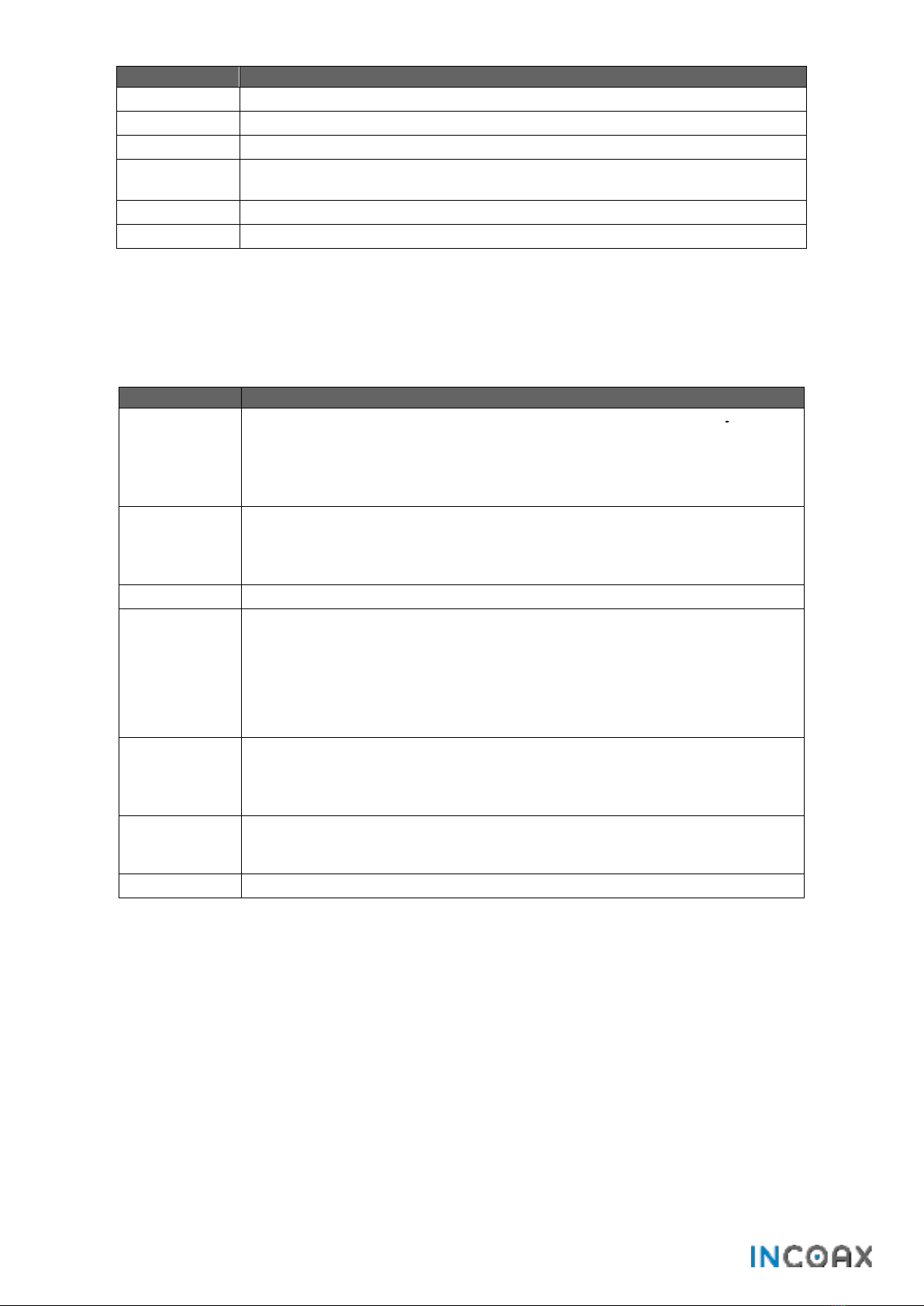
The InCoax D2501 MoCA Access DPU System consists of a Persistent Management Agent Aggregator (PMAA) if
NETCONF/YANG communication protocol is used or Automatic Configuration Server (ACS) if Configuration
WLAN Management Protocol (CWMP) is used, hereafter called Management System, which manages the DPUs
installed in, or near, buildings and Modems installed in the customers’ homes. An illustration of the
Management System can be seen in Figure 1. The Modem is easily connected by the customers without any
requirements for customer configuration. This architecture makes the MoCA Access DPU System very flexible
supporting different types of networks. Once the DPU has been installed in, or near, the building the only
required operation to connect new customers is to provide them with a Modem. (Please refer to the InCoax
handbook System Design Guidelines for Cable Technicians for guidance.) As soon as the Modem has been
connected to the coaxial network, it will automatically be detected and configured by the DPU through the
Management System (if such setup has been enabled in the Management System).
The typical MoCA Access DPU System consists of distributed Management System Architecture which handles
thousands of DPUsand millions of Modems. If there is a legacy cable-TV service in the building the TV signal
must be combined with the broadband signal using the Diplexer Filter. The Management System is used as a
customer configuration, monitoring, and provisioning tool through a web interface or be accessed by
provisioning system or Operating Support System through NETCONF or TR-069 interface.
Figure 1— Overview of the Management System.
4.2 The DPU
The DPU acts as a bridge between the incoming XGS-PON, GPON, EPON or Ethernet access network and
customers’ Ethernet Modem port, using the in-building coaxial network as transport for data traffic to the
Modems. The DPU communicates with all Modems, over dedicated RF bands, in the coaxial network to manage
their individual configuration, enforces traffic, and security policies. It also collects and stores traffic statistics
data from the network.
InCoax D2501
Copyright © 2021 InCoax Networks AB. All rights reserved.
Confidential under NDA
4.3 MoCA Access Modem
The Modem is available in different models. There are also different variants depending on which MoCA band
is used.
The Modem connects to any antenna outlet in the subscribers’ homes for easy self-installation. It communi-
cates with the DPU to get configuration parameters and connects to the subscribers’ Ethernet modem RJ45
port. The firmware of the Modem can be upgraded from the DPU.
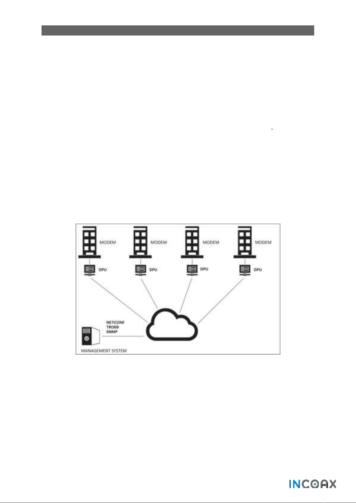
4.4 Principal deployment model
Figure 2 shows an example of the in-building principal deployment model of D2501.
Figure 2— Overview of principal deployment model.
InCoax D2501
8 Copyright © 2021 InCoax Networks AB. All rights reserved.
Confidential under NDA
5Coaxial Network Use Cases
In general, the D2501 can be used for different coaxial network use cases depending on the used spectrum for
the current TV/DOCSIS services. MoCA Access have five default frequency bands and InCoax has added two
additional frequency bands as presented hereunder:
•Band A-A 400-900 MHz for residential networks with specified spectrum up to 1002 MHz.
•Band A-AH 550-850 MHz for hotel networks with specified spectrum up to 862 MHz.
•Band A-AS 400-800 MHz co-existence in satellite networks with spectrum up to 2150 MHz.
•Band A-B 800-1300 MHz co-existence in TV networks with a spectrum up to 1300 MHz.
•Band A-C 1025-1675 MHz co-existence in TV / DOCSIS 3.0 networks with a spectrum up to 1800 MHz.
•Band A-D 1125-1675 MHz co-existence in TV / DOCSIS 3.0 networks with a spectrum up to 1800 MHz.
•Band A-E 1375-1675 MHz co-existing in TV/DOCSIS 3.1 networks with a spectrum up to 1800 MHz.
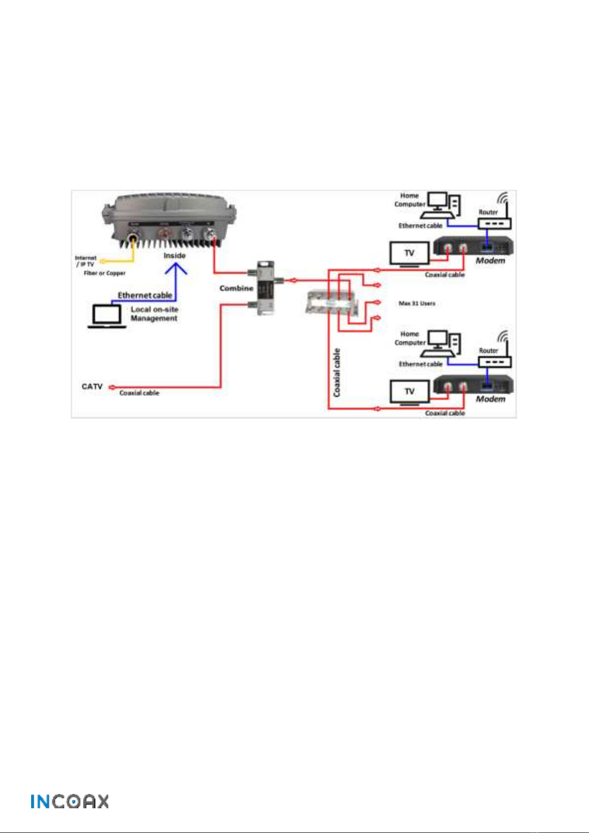
5.1 Coexistence with Terrestrial TV, 47 - 694 MHz
MoCA frequency band A-B combined with terrestrial TV in a Cascade (Figure 3), Star coaxial network (Figure 4)
and US Home Run networks (Figure 5).
Figure 3— Set up for the use case “Terrestrial TV” (Cascade network).

InCoax D2501
Copyright © 2021 InCoax Networks AB. All rights reserved.
Confidential under NDA
Figure 4—Set up for the use case “Terrestrial TV” (Star network).
Figure 5—Set up for the use case “Terrestrial TV” (US Home Run network).
InCoax D2501
10 Copyright © 2021 InCoax Networks AB. All rights reserved.
Confidential under NDA
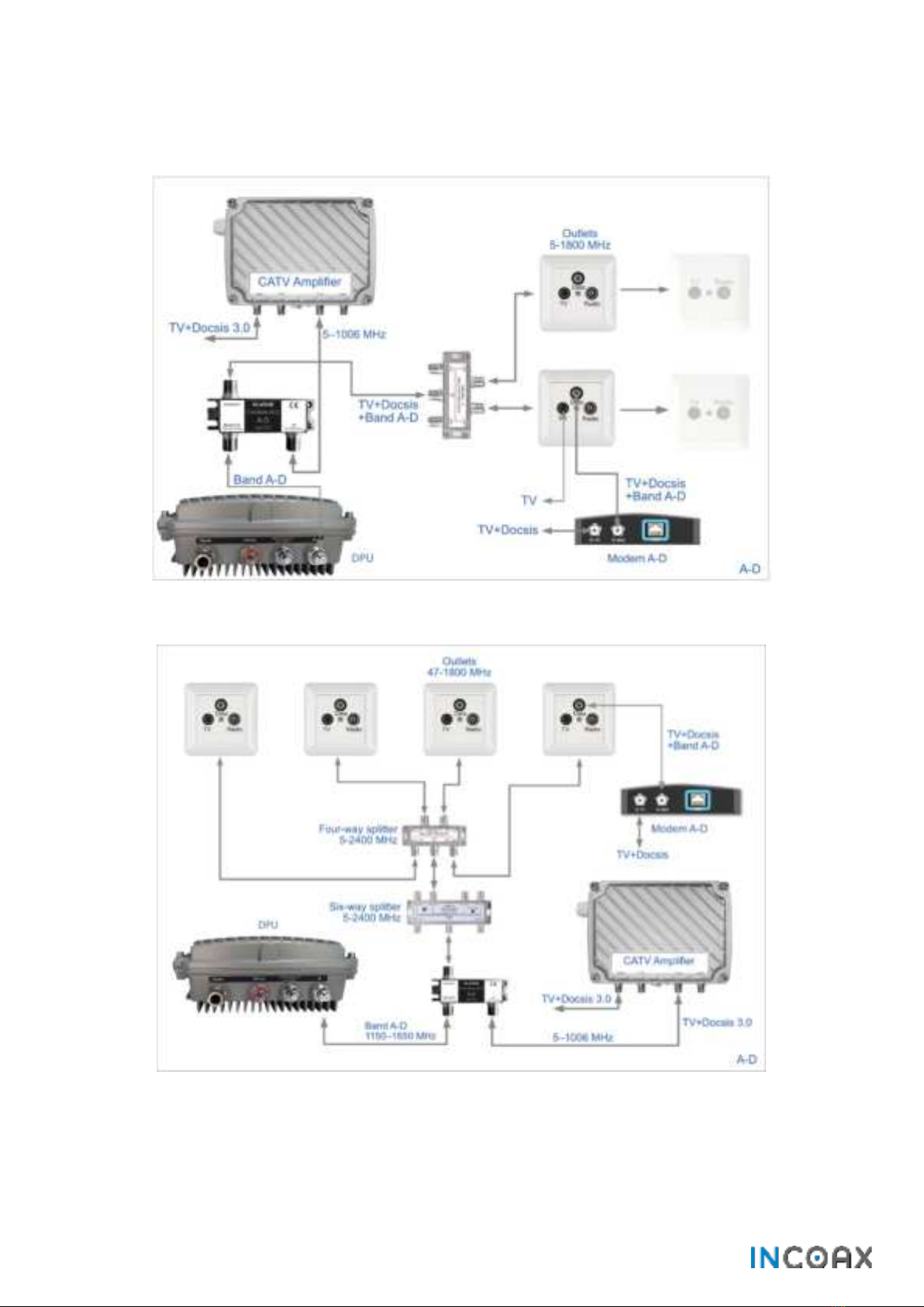
5.2 Coexistence with Cable TV/DOCSIS 3.0
MoCA frequency band A-D combined with Cable-TV/DOCSIS 3.0 in a Cascade (Figure 6) and Star coaxial network
(Figure 7).
Figure 6— Set up for the use case “Cable TV/DOCSIS 3.0” (Cascade network).
Figure 7—Set up for the use case “Cable TV/DOCSIS 3.0” (Star network).
InCoax D2501
Copyright © 2021 InCoax Networks AB. All rights reserved.
Confidential under NDA
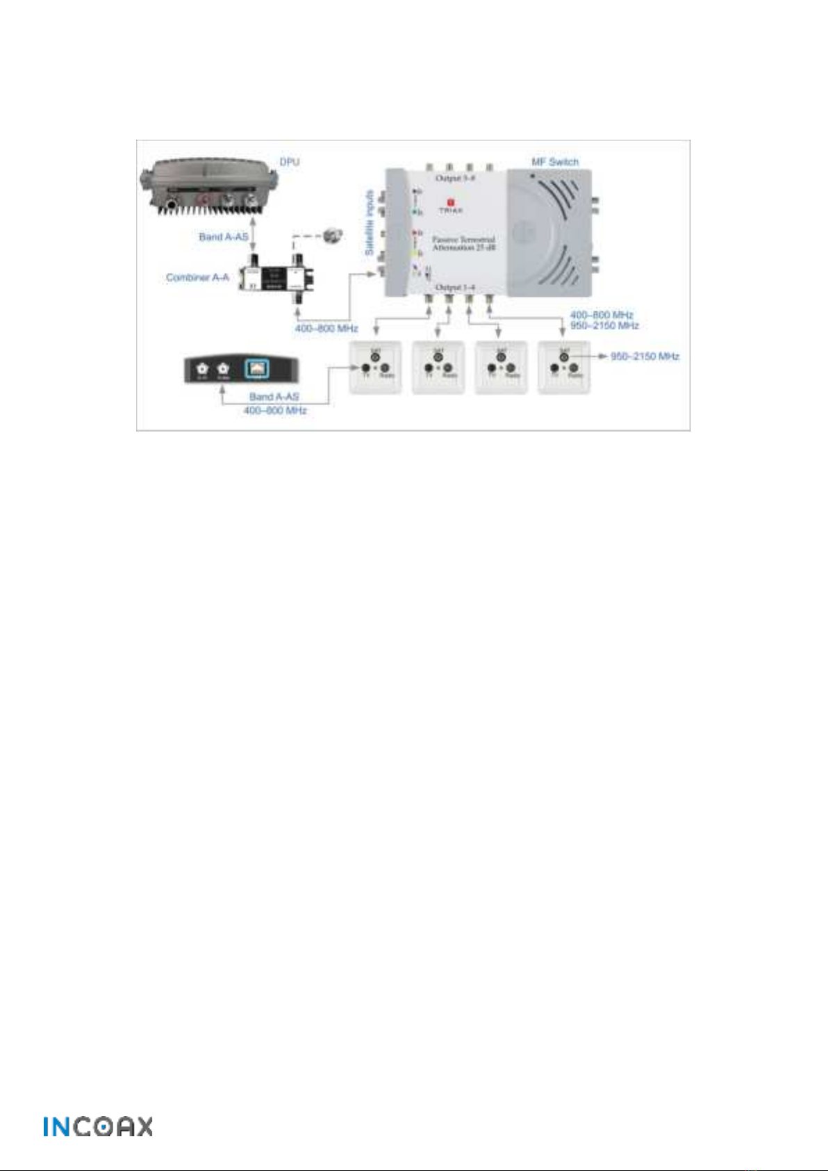
5.3 Coexistence with Satellite
High frequency Satellite-TV signals combined with MoCA frequency band A-A (A-AS). See Figure 8.
Figure 8—Set up for the use case “Satellite”.

InCoax D2501
12 Copyright © 2021 InCoax Networks AB. All rights reserved.
Confidential under NDA
6DPU Web Interface Access
The DPU can be managed via the management port using a web interface. Please refer to the InCoax document
“Configuration Manual” for a more detailed description of the web interface and how to set up the DPU. See
reference {f}.
6.1 Accessing the DPU Web Interface
Connect a computer with an Ethernet cable to the Management port on the DPU (under the
front cover), marked MGMT RJ45. See Figure 9. (InCoax recommends using the cable type
CAT5e as a minimum for best performance.)
Figure 9— The DPU’s panel connections.
For best user experience
InCoax recommends you
to enable JavaScript.

InCoax D2501
Copyright © 2021 InCoax Networks AB. All rights reserved.
Confidential under NDA
7Specifications
The electrical, physical and functional specifications for the D2501 DPU. Please note that the specification may
be subject to change.
Performance • Based on MoCA Access 2.5 Profile D. See reference {c}.
•2.5 Gbps throughput on the MoCA port with 30dB SNR.
•3.2 Gbps throughput on the MoCA port with 40dB SNR.
•Max 31 Modems.
•MoCA Bands: A - A, A - AH, A - AS, A - B, A - C, A - D and A - E
•Frequency range: 400 to 1675 MHz
•RF channel bandwidth: 100 MHz
•Bonded operation supporting 3, 4, or 5 RF channels.
•17 dBm maximum output power; automatically adjusted per modem.
•Configurable beacon frequency.
•Modulation: OFDM, QAM 8, 16, 32, 64, 128, 256, 512, or 1024; BPSK and QPSK
•Multiplexing methods: TDMA/TDD
•Communication: Half-duplex
Physical: • Northbound fiber SFP+ port inside enclosure.
•Multi Source Agreement (MSA) compliant, SerDes – 10 Gbps data rate, SFF-8472 (see
reference {h}) – Diagnostics interface.a
•Supporting XGS-PON, XG-PON, GPON, EPON and Active Ethernet.
•Management Ethernet port inside enclosure: 10 / 100 / 1000 Mbps, configuration and
statistics port.
•RJ-45 connector supports type CAT5 UTP (as a minimum).
•One coax out with PG-11.
•F-female connector - 3/8-UNEF32, 75 Ω
•F-female connector - 3/8-UNEF32, 75 Ω for 13-25VDC power feed
Indicators • Power on, Management, Trunk, Coax Link traffic and alerts.
• External led indication on ZTP and system initiation and status.
Dimensions • 257 × 203 × 100 mm (W × H × D)
•Wall mount
Weight • 3 kg
Environmental • Operating temperature: -30 °C to +70 °C
•Relative humidity: 20 % to 80 %
•Altitude: maximum 2000 m
•Dynamic temperature control with cooling redundancy.
•Abnormal operation conditions alarms
•Storage (non-condensing): -40 °C to +70 °C and 5 % to 90 % relative humidity
•RoHS and RoHS 2. See reference {b}
•UL 94 V-0. See reference {i}
Power • 100-240VAC, 50/60Hz
• 13-25VDC
•Power consumption 12 W nominal.
•Automatic power on after power grid failure.
aInCoax recommends using the SFP+ module:
Fiber MM: Ubiquiti 10G UF-MM-10G
Fiber SM: InCoax 10G OS-SP96-3110D/ Ubiquiti 10G UF-SM-10G/ Ubiquiti Bi-Di UF-SM-10G-S/ Finisar FTLX1475D3BTL/
NorthLab NORT-1031-LRT/ FS 10GBASE-BX BiDi SFP+ 1330nm-TX/1270nm-RX 10km DOM Transceiver Module/
FS 10GBASE-BX BiDi SFP+ 1270nm-TX/1330nm-RX 10km DOM Transceiver Module
Copper: MikroTik 10G S+RJ10/ Ubiquiti 10G UDC-2

InCoax D2501
14 Copyright © 2021 InCoax Networks AB. All rights reserved.
Confidential under NDA
IEEE Standards • IEEE 802.3 (Ethernet) {k}
•IEEE 802.3u (Fast Ethernet) {m}
•IEEE 802.1p (Priority tags) {g}
•IEEE 802.1q (VLAN with full VLAN-ID range. Up to 200 VLAN Configurable internal VLAN
for policing, shaping and prioritization for ingress untagged frames) {a}
•IEEE 802.1ad (QinQ) {j}
Approvals • FCC ID 2ATQM1000-0XXX {n}
•Marking: CE (see section 8.1.2), FCC (see section 8.1.3), IC, TUV SUD NRTL (see section
8.1.4), UKCA (see section 8.1.5)
•EMC: EN55032:2015 Class B, EN55035:2017 {o}, FCC Part 15 B Class B, ICES-003 Class B
(see section 8.1.1), ETSI EN 300386, V2.1.1:2016-07 + Annex D
•Safety: IEC62368-1:2014, EN62368-1:2014 {p}+ A11:2017, AS/NZS 62368.1:2018,
CSA/UL 62368-1:2014
•ROHS: ROHS 2.0
Security • DHCP snooping, Option 82 rewrite and trusted/untrusted clients, limit setting,
configurable options per VLAN.
•Blocking of unknown CPE.
•Broadcast storm protection from clients.
•Support for PPPoE IA option 0x105 Remote ID.
Multicast • IGMP snooping (v2,v3).
•IGMP filtering per VLAN.
•Configurable IGMP timeout.
•Multicast VLAN Registration.
•Bandwidth reservation per multicast group.
•Max. 256 Multicast groups and MAC addresses.
QoS • Traffic classification.
•Mapping and remarking.
•Congestion management.
•Strict priority, four separate queues for broadcast, multicast, and unicast.
•Configurable rate limitation per queue.
•Configurable upstream/downstream ratio.
Management • IPv4 WEB GUI via https.
•NETCONF / YANG.
•CWMP -TR069
•MoCA Access MIB and TR-181
•Statistics and system/version information.
•Configuration.
•Define and assign service profiles.
•Built in spectrum analyzer.
•Access through management VLAN or separate management Ethernet port.
•Remotely upgradable.

InCoax D2501
Copyright © 2021 InCoax Networks AB. All rights reserved.
Confidential under NDA
8Legal Information
8.1 Regulatory Notice and Statement (Class B)
Model List: InCoax D2501
8.1.1 Canada
The following information applies if the product is used within the Canada area.
Industry Canada ICES Statement
CAN ICES-003 Class B. See reference {q}.
8.1.2 European Union
The following information applies if the product is used within the European Union.
CE EMC Statement
Warning: This equipment is compliant with Class B of EN 55032. In a residential environment this equipment
may cause radio interference. See reference {o}.
8.1.3 United States of America
FCC Part 15 B Class B
The following information applies if the product is used within the USA area.
This equipment has been tested and found to comply with the limits for a Class B digital device, pursuant to
part 15 of the FCC Rules. See reference {n}. These limits are designed to provide
reasonable protection against harmful interference when the equipment is operated in a commercial
environment. This equipment generates, uses, and can radiate radio frequency energy and, if not installed and
used in accordance with the instruction manual, may cause harmful interference to radio communications.
Operation of this equipment in a residential area is likely to cause harmful interference in which case the user
will be required to correct the interference at the user's own expense.
Caution: Changes or modifications not expressly approved by the party responsible for the compliance could
void the user’s authority to operate the equipment.
8.1.4 TUV SUD NRTL
This equipment is compliant with the UL62368-1, CAN/CSA-C22.2 NO. 62368-standard.
TÜV SÜD is an OSHA recognized Nationally Recognized Test Laboratory (NRTL), a Certified Body
and Inspection Body with SCC (Standards Council of Canada), an accredited EMC Testing laboratory
with A2LA, and many others. TÜV SÜD is authorized by OSHA (Occupational Safety & Health
Administration) as a NRTL capable of performing product safety testing to UL/ANSI Standards.
8.1.5 Great Britain
The UKCA (UK Conformity Assessed) product marking is used for goods being placed on the market
in Great Britain (England, Wales and Scotland). The UKCA marking alone cannot be used for goods
placed on the Northern Ireland market, which require the CE marking or UKNI marking.
It corresponds to the EU CE marking and covers most goods which previously required the CE marking.
UKCA (CE) EMC Statement
Warning: This equipment is compliant with Class B of EN 55032. In a residential environment this equipment
may cause radio interference. See reference {o}.

InCoax D2501
16 Copyright © 2021 InCoax Networks AB. All rights reserved.
Confidential under NDA
9Disposal of Equipment
9.1 Waste Electrical and Electronic Equipment
The Waste Electrical and Electronic Equipment Directive (WEEE Directive) is the European Community Directive
2002/96/EC on waste electrical and electronic equipment which, together with the Restriction of Hazardous
Substances Directive (RoHS Directive) 2002/95/EC (also known as RoHS 1) became European Law in February
2003. The WEEE Directive was amended into the Directive 2012/19/EU and the RoHS 1 has been evolved into
the RoHS 2 Directive 2011/65/EU. See references {r} and {b}, respectively.
The symbol adopted by the European Council to represent WEEE comprises of a crossed-out wheelie
bin. The black rectangle below the wheelie bin indicates that the product has been placed on the
market after 2005, when the WEEE Directive came into force. The symbol shall be placed on the
products, packaging, and/or accompanying documents. It means that used electrical and electronic
products and batteries should not be mixed with general household waste but taken to a designated
collection site as indicated by the local authorities. In accordance with national legislation and the
WEEE Directives 2002/96/EC and 2012/19/EU, and the Battery Directive 2006/66/EC amended by
2013/56/EU. See reference {s}.
For more information about collection and recycling of old products and batteries, please contact the local
municipality, the local waste disposal service, or the point of sale where the item was purchased. Penalties may
be applicable for incorrect disposal of this waste, in accordance with national legislation.
9.2 For Business Users in the European Union
Please contact the dealer or supplier for further information to discard electrical and electronic equipment.
9.3 Disposal in Countries Outside the European Union
The symbol has only validity in the European Union. Please contact the local authorities or dealer and ask for
the correct method of disposal.
9.4 Battery Symbol
The WEEE symbol can be supplemented with one or more chemical symbols to indicate what kind of battery is
used in the product. The chemical symbols will then be placed under the black rectangle.
This manual suits for next models
2
Table of contents


