Incra Shop Stop User manual

First:
Loosen screw
Horizontal stop rod
Second:
Slide stop rod
2
INCRA Woodworking Tools & Precision Rules
Expandable two-piece
body to accommodate
wooden subfences
Micro
adjust
screw
INCRA saw
tooth rack
Vertical T-bar
slides up or
down to
accommodate
different fence
heights
Horizontal rod moves in and
out to extend stop surface
FEATURES
The INCRA Shop Stop comes equipped with two
interchangeable and reversible stop surfaces – a vertical stop
arm which can be adjusted up or down to accommodate
different fence heights, and a horizontal stop rod which can be
useful in extending the stop surface forward beyond the actual
body of the stop. Further, by removing the stop rod and stop
arm, user-made wooden stop pieces can be screwed into the
T-slot to provide the perfect stop surface for even the most
unusual wood profiles. The two-piece expandable Shop Stop
body design allows you to add
3
⁄
4
" thick wooden sub-fences to
your INCRA fence for zero clearance applications without
compromising the use of the stop. The patented incremental
positioning of INCRAʼs sawtoothed racks allows perfectly
repeatable stop locations at any multiple of
1
⁄
32
", while the
micro adjust screw permits easy fine adjustments anywhere
between the
1
⁄
32
" tooth spacing. (See Fig. 1)
ADJUSTMENTS
When adjusting
the vertical stop arm,
leave a small gap
between the end of the
stop arm and the router
table, drill press or table
saw top. This provides
clearance for sawdust.
Vertical stop arm
First:
Loosen screw
Second: Slide vertical
stop arm up or down to
desired position Indexing lip
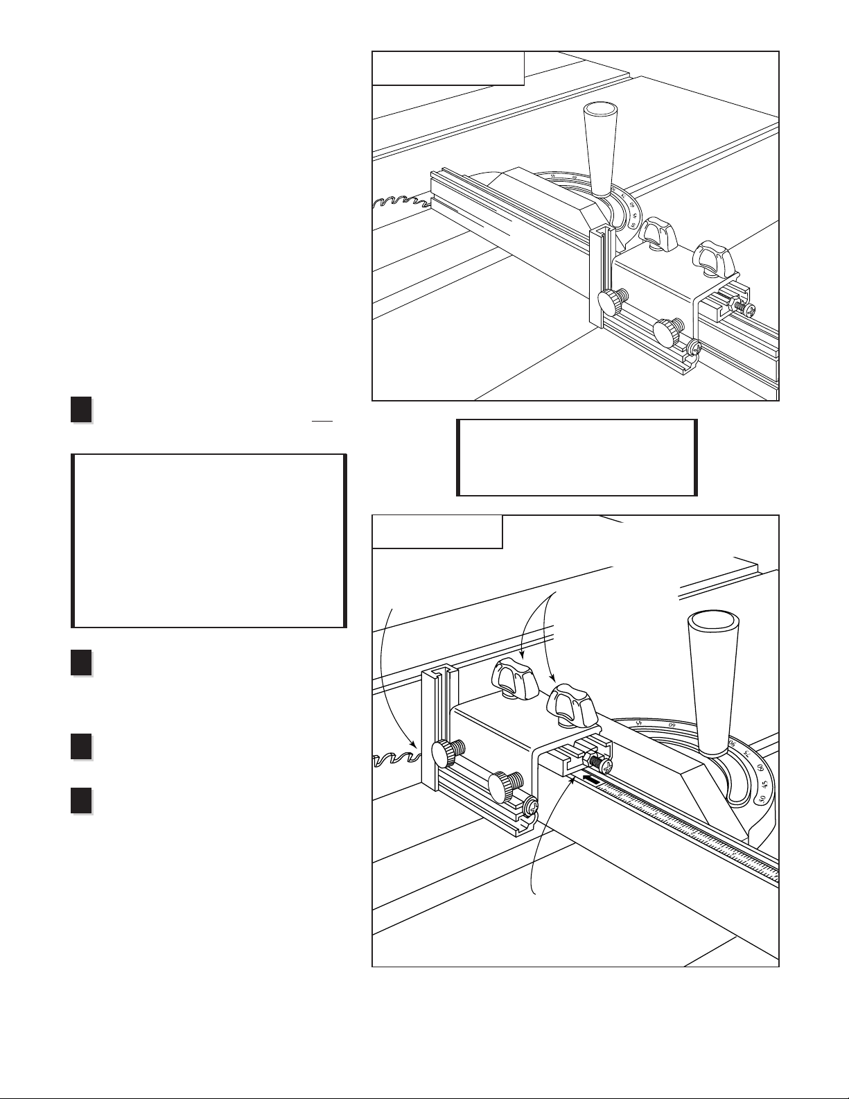
Horizontal Stop Rod:
The horizontal stop rod is held in place by a #10-32 x 3⁄8"
machine screw. To adjust the position of the stop rod, loosen
the screw and slide the rod as necessary, then retighten the
screw (Fig. 4)
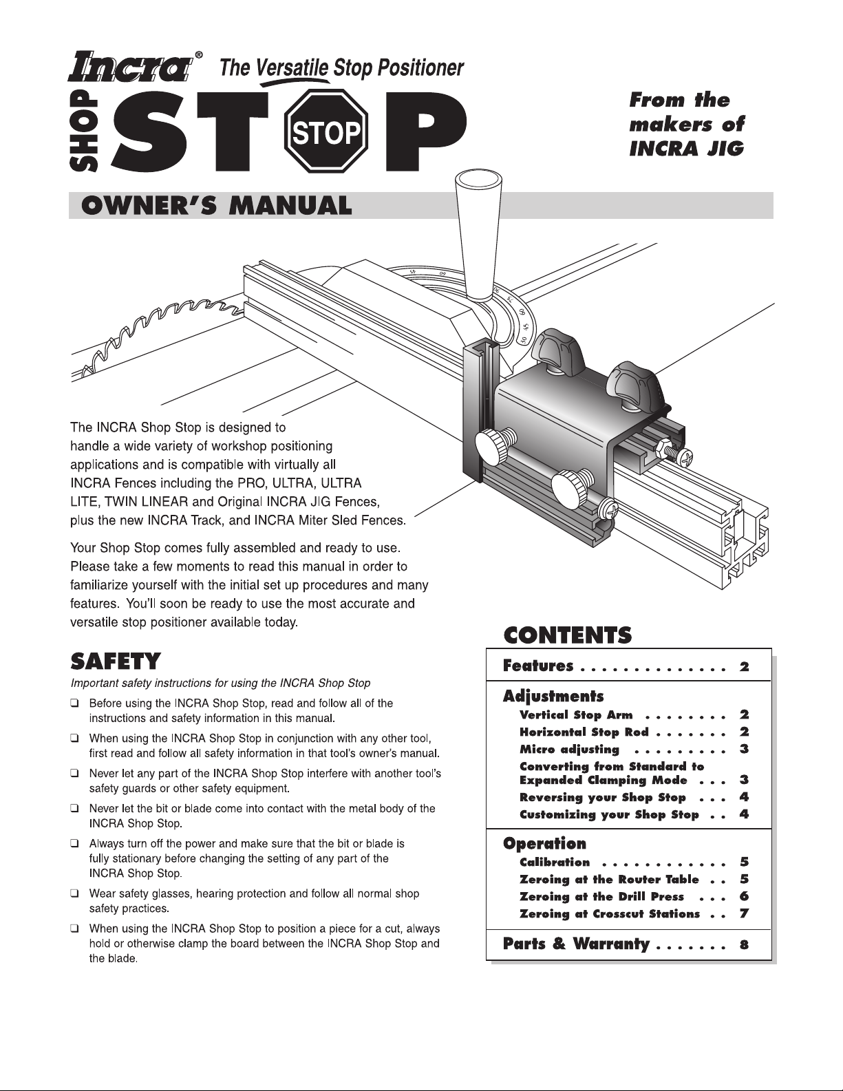
Vertical Stop Arm:
To adjust the vertical stop arm up or down, loosen the
machine screw as shown in Fig. 2 and slide the stop arm to
the desired position. As you tighten the screw, make sure
the indexing lip on the stop arm is pressed against the face
of the stop body. (Fig. 3)
CAUTION: Always unplug the
motor before zeroing your Shop
Stop to any power tool.
FIG. 1
Shop Stop features
FIG. 2
Adjusting vertical stop arm
FIG. 3
Top view of stop arm position
FIG. 4
Adjusting
horizontal
stop rod

Micro adjusting:
Fine-tuning the position of your Shop Stop relative to a
cutter is easy and accurate. Just loosen the two black
thumbscrews on top of the Shop Stop body about
1
⁄
8
turn,
then turn the machine screw located at the end of the Shop
Stop (Fig. 5). Each full turn of the screw moves the stop
exactly
1
⁄
32
". Turning the screw clockwise moves the stop
surface closer to the cutter. To move the stop surface away
from the cutter, turn the screw counterclockwise as you
push the stop body toward the screw. Always tighten the
two black thumbscrews after micro adjusting.
Converting from standard to expanded
clamping mode:
Your INCRA Shop Stop comes assembled in the standard
clamping mode. This setup will clamp to virtually any of the
INCRA Fences including the ULTRA, ULTRA LITE, TWIN
LINEAR and Original INCRA JIG Fences plus the New INCRA
Miter Sled and the INCRA Track. In the standard mode you
can even clamp the Shop Stop directly to any piece of
3
⁄
4
"
plywood or hardwood. Youʼll find this feature perfect for those
occasions when you want to extend the length or height of
your INCRA fence with a
3
⁄
4
" subfence. A second “expanded”
clamping mode allows the use of your Shop Stop after attaching
a wooden auxiliary fence to your INCRA Fence. (Fig 6).
Adding a wooden auxiliary fence to your INCRA Miter Sled,
chop saw, or INCRA JIG Fence can be very beneficial in that it
provides zero clearance between the cutter and the fence. A
zero clearance auxiliary fence often translates to safer and
cleaner cuts since the smaller opening provides more support
for the workpiece at the cut.
The two piece design of the INCRA Shop Stop permits use of
a
3
⁄
4
" thick wooden auxiliary fence without interfering with the
stop's ability to clamp to your INCRA Fence. To change the
stop to expanded mode, loosen the two black thumbscrews
and slide the stop body (red) off of the stop cap (gold). Now
slide the two rectangular nuts on the stop body into the
alternate T-slot on the cap. (See Fig. 7) Tighten the two
clamping knobs.
Attach the auxiliary fence as described in your INCRA
Fence ownerʼs manual.
INCRA Shop Stop Manual
3
First: Loosen both black thumbscrews.
Leave white thumbscrews fully
tightened if already installed on fence.
Second:
Turn micro adjust
screw clockwise to
move the stop
toward the cutter.
Turn counter-
clockwise and slide
stop body toward
micro adjust screw
to move stop away
from cutter.
Stop body
Third: Retighten both
black thumbscrews
3/4" wooden
auxiliary fence
FIG. 5
Micro adjusting
FIG. 6
Expanded clamping mode
Shop Stop
shown in expanded
clamping mode
Stop
body
Loosen black thumbscrews
and slide stop body off of cap
Large gap
Reassemble stop body
to stop cap as shown
Standard Mode Expanded Mode
FIG. 7 Converting from standard to expanded clamping mode
Stop cap
Note:
For auxiliary fence applications where
incremental use of the Shop Stop is required, use
3
⁄
4
" hardwood or plywood and make sure that the
auxiliary fence is no taller than your INCRA Fence.
Stop cap
Small gap

Reversing your Shop Stop:
At some cutting stations it may be desirable to reverse
the stop surfaces of the INCRA Shop Stop. This allows
the Shop Stop to function as either an infeed or outfeed
stop at the router table, or on either side of the blade at a
chop saw or radial arm saw.
To reverse your Shop Stop, first move the micro adjust
screw to the opposite end of the gold stop cap and
tighten the nylon nut against the aluminum. Remove and
reverse the #10-32 x 3-
1
⁄
2
" machine screw that holds the
vertical stop arm to the red stop body. Replace the stop
arm on the opposite end of the stop body. Make sure the
indexing lip on the arm wraps around the front of the stop
body (Fig. 3) and that the arm is flat against the end of
the body. Tighten the machine screw. (Fig. 8)
#10-32 nylon
hex nut
Stop
body Vertical
stop arm
Hex nut
slides into
T-slot on
vertical
stop arm
#10-32 x 1"
micro adjust
screw
Stop cap
4
INCRA Woodworking Tools & Precision Rules
FIG. 9
FIG. 8
Reversing the Shop Stop
#10-32 x 3 1⁄2"
machine screw
#10 flat washer
FIG. 10
#10-32 hex nuts
1⁄4"
diameter
hole
#10-32 x 3⁄4"
machine screws
1⁄2"
3⁄16"
3⁄4" or
more
Note:
Should you ever remove the
micro adjust screw, make sure to
tighten the nylon nut against the
aluminum when replacing it. The
nylon nut keeps the micro adjust
screw from vibrating loose during
cutting operations.
Example of user-made
wooden stop surface
designed to position
boards with mitered ends
1⁄2"
FIG. 11
Customizing your stop
DETAIL 11A
#10
flat
washer
1⁄2"
Customizing your Shop Stop:
By removing both the vertical stop arm and the
horizontal stop rod, user-made wooden stops
can be attached to the front face of the stop.
Youʼll find this feature useful when you want the
stop surface to match an odd-shaped wood
profile or a mitered board end. Fig. 11 describes
just one example of a user-made stop. By gluing
two pieces of wood together, an “L” shape can be
produced which can be cut to match the desired
profile and then screwed into the T-slot. The “L”
feature on the block can be glued on to protrude
up, down, in or out as desired.
Reversible
stop surface
Note:
Whenever reversing
the Shop Stop, always make
sure the stop surface
selected (vertical arm or
horizontal rod) protrudes at
least
1
⁄
8
"
in front of the end
of the gold stop cap.
Otherwise taller workpieces
will be stopped by the gold
stop cap rather than the
selected stop surface.
Reversible
stop surface
2"

INCRA Shop Stop Manual
5
First: Slide a
square cut board
up to contact the
“high spot” on the
router bit
Second: Clamp
the Shop Stop to
the fence with the
stop surface as
close as possible
to the board.
Micro adjust
screw
Third: Loosen black thumbscrews 1⁄8
turn, then rotate micro adjust screw
clockwise until stop surface touches
end of board. Tighten the
black thumbscrews.
Fourth: Slide scale to
read directly under end
of gold stop cap. Use
one of the initial
scale settings
described
in Fig.13.
FIG. 12
Follow these steps for
zeroing at the router table
OPERATION
FIG. 13
Slide scale on your fence to one of three initial positions
ASlide scale to 0" for
a direct readout of
dimension “A” (total
length of cut)
BSlide scale to “minus
1⁄2of bit diameter”
for a direct readout
of dimension “B”
CSlide scale to “minus
bit diameter” for
direct readout of
dimension “C”
Zeroing at the Router Table:
For most applications at the router table you will be using your Shop Stop on
the outfeed fence to limit the length of a cut relative to the front end of a board.
Follow the steps in Fig. 12 below.
Calibrating the Shop Stop
for your Workstation:
In order for your INCRA Shop Stop to
accurately locate your workpiece for a cut, you
must first “zero” your Shop Stop to the bit or
blade and position the sliding scale on your
fence. Zeroing is often just as simple as
clamping your Shop Stop to the fence with the
stop surface just touching the bit or blade. You
want the stop surface to be zero distance from
the cutter, so a little micro adjusting might be
required. Once this zero position is found, slide
the scale on your INCRA Fence to read “0”
directly under one end of the gold stop cap. This
approach, however, wonʼt handle every situation
in the shop. Sometimes, as in the case of a
router or drill bit, it becomes necessary to use an
indirect approach to setting the initial scale
position. For zeroing at the router table, drill
press and crosscut stations, a step-by-step
approach ensures an easy and accurate setup.
See Figs. 12 thru 15 for the steps.
Note:
The vertical stop arm is the stop
surface illustrated in all of the examples to
follow, but donʼt rule out the use of the
horizontal rod for your stop surface.
Once the Shop Stop is zeroed to the router bit
as shown in Fig. 12, you now have the choice
of setting the sliding scale on your INCRA
Fence to one of three initial positions.
See Fig. 13.

6
INCRA Woodworking Tools & Precision Rules
1
2
If youʼre not using the horizontal rod on
your Shop Stop as the stop surface, it can
be used as your drill press set up rod.
3
Second: Install 1⁄4" set up
rod and slide square cut
board up to touch 1⁄4" rod
Third: Clamp the Shop Stop
to the fence with the stop
surface as close as possible
to the board.
Fourth: Loosen black
thumbscrews 1⁄8turn,
then rotate micro adjust
screw clockwise until
stop surface touches
end of board. Tighten
thumbscrews.
Fifth: Slide scale to read
negative 1⁄8" directly under
end of gold stop cap.
Micro adjust
screw
1⁄4" diameter “set
up” rod or 1⁄4"
diameter drill bit
FIG. 14
Zeroing at the drill press
First: Set the distance
between your INCRA
fence and the center of
the bit as required by
your project.
4
5
Zeroing at the Drill Press:
Zeroing at the drill press is really the same as zeroing at a
router table. Stop locations at a drill press, however, are almost
always located relative to the center of the bit, not the edge of
the bit. Because of this, and the fact that drill bits are available
in so many different sizes (decimal, 64ths, metric, letter and
number), it is a good idea to use a specific “set up” rod or drill
bit each time you zero your Shop Stop. The “set up” rod should
have a diameter that is some multiple of
1
⁄
16
". In the steps
following weʼll use a
1
⁄
4
" rod for the set up.
Set the distance between your INCRA Fence and the
center of the drill bit as required by your project. An
INCRA JIG at your drill press makes this step really easy.
Otherwise use a bradpoint drill bit and a ruler, or mark drill
center lines on your workpiece and use these lines to
initially position your INCRA Fence.
Install a short length of
1
⁄
4
" steel rod in your drill press (a
1
⁄
4
" twist drill bit will also work well). Place a square cut
piece of scrap stock against the fence with the end of the
board against the
1
⁄
4
" rod.
Lock the INCRA Shop Stop to the fence with the selected
stop surface (vertical arm or horizontal rod) as close as
possible to the end of the board.
Loosen the two black thumbscrews about
1
⁄
8
turn,
then rotate the micro adjust screw clockwise until the
stop surface touches the end of the board. Tighten the
black thumbscrews.
Slide the scale on your fence to read minus
1
⁄
2
of the
set up rod diameter. In this case, since we used a
1
⁄
4
"
diameter set up rod, weʼll slide the scale to read
negative
1
⁄
8
" directly under the end of the gold stop cap.
(The scale can be set to read under either end of the
gold stop cap.) Use the end that gives the best visibility.
When set to this initial position, the scale reading at any
subsequent Shop Stop location will give you a direct
readout of the distance from the end of the workpiece to
the center of the hole.
Loosen the black thumbscrews about
1
⁄
8
turn then rotate the micro adjust screw
clockwise until the stop surface touches the
teeth on your saw blade. Tighten the
thumbscrews.
Slide the scale on your fence to read 0"
directly under the end of the gold stop cap.
(Use the end farthest from the saw blade)
Now at each subsequent setting of your
Shop Stop, the scale will give a direct
readout of the distance between the stop
surface and the saw blade.
Zeroing at Crosscut Stations:
There are several stations in the shop where
crosscutting operations can take place – the radial
arm saw, chop saw, sliding miter saw, and the table
saw. The radial arm saw, chop saw and sliding
miter saw are all similar in that the workpiece is held
against a stationary fence as the blade is moved
through the cut. At the table saw, crosscutting is
accomplished with the help of a miter gauge or by
using a crosscut box. In these approaches the
workpiece is held against a fence that is moved,
guided by the miter slots in the table saw, over a
stationary blade. In any case, accessorizing these
tools with an INCRA Track and INCRA Shop Stop
makes accurate crosscutting effortless.
Zeroing at these tools is easy.
Here’s how:
With the saw unplugged, raise the blade about 1"
and clamp the Shop Stop to your INCRA fence with
the stop surface as close as possible to the blade.
Position fence far enough away from the
blade to comfortably clear the blade at ALL
cutting angles. CAUTION: Always unplug the
motor before zeroing your Shop
Stop to any power tool.
INCRA Shop Stop Manual
7
Second: Clamp stop to
fence with stop surfaces
as close as possible to
saw blade. Third: Loosen black
thumbscrews about 1⁄8
turn, then rotate micro
adjust screw clockwise
until stop touches teeth
on saw blade. Tighten
black thumbscrews.
Fourth: Slide scale to
read 0" directly under
end of gold stop cap.
FIG. 15
Typical crosscut application
1
2
3
First: Position fence far enough away from
the blade to comfortably clear the blade
at all cutting angles
4
Note:
Depending on the distance of the
end of the fence to the blade (as determined
in Step 1 above), one of the white thumb-
screws may overhang the end of the fence
when zeroing. Just be sure that during any
cutting operation, the Shop Stop is
positioned sufficiently far enough away from
the blade for safe finger clearance, and that
both white thumbscrews are engaged
against the fence surface.
FIG. 16
Zeroing at the tablesaw

Made in America by:
Taylor Design Group, Inc. ■P.O. Box 810262 ■Dallas, Texas 75381 ■Web Site: www.incra.com 0199
Printed in the U.S.A. © 1999, Taylor Design Group, Inc. INCRA is a registered trademark of Taylor Design Group, Inc.
PRODUCT INFORMATION
For a product information update on the complete
INCRA line of tools, please see your nearest dealer. If
you are unable to locate a store nearby, or if you have
trouble finding a particular product, we will honor your
order directly.
For a product information brochure, call, write or fax to:
Taylor Design Group, Inc.
P.O. Box 810262, Dallas, TX 75381
Tel: (972) 418-4811 Fax: (972) 243-4277
Web Site: www.incra.com
WARRANTY
Taylor Design Group, Inc. warrants this product for one year from date of purchase. We will repair any
defects due to faulty material or workmanship, or at our option, replace the product free of charge.
Please return the failing component only, postage prepaid, along with a description of the problem to
the address below. This warranty does not apply to parts which have been subjected to improper use,
alteration, or abuse.
LIFETIME WARRANTY ON POSITIONING RACKS
If an INCRA positioning rack in this tool becomes damaged for ANY reason, Taylor Design Group will
replace it free of charge for as long as you own your tool. Return the damaged rack, transportation
prepaid, and allow 1 to 2 weeks for delivery.
NOTE:
Replacements cannot be sent unless damaged racks have been received by Taylor Design Group.
PARTS AND OPTIONAL ACCESSORIES
Part # Part Description Price
SHOPSTOP INCRA Shop Stop . . . . . . . . . . . . . . . . . . . . . . . . . . . . . . . . . . . . . . . . . . . . . . . . . . . . . . . . $ 32.95
Add a second Shop Stop to your INCRA Fence or INCRA Track for mortising and other applications
TRACK18 18" Track Section . . . . . . . . . . . . . . . . . . . . . . . . . . . . . . . . . . . . . . . . . . . . . . . . . . . . . . . . $ 27.95
TRACK36 36" Track Section . . . . . . . . . . . . . . . . . . . . . . . . . . . . . . . . . . . . . . . . . . . . . . . . . . . . . . . . $ 42.95
TRACK52 52" Track Section . . . . . . . . . . . . . . . . . . . . . . . . . . . . . . . . . . . . . . . . . . . . . . . . . . . . . . . . $ 52.95
Add one or more individual INCRA Track Sections for placing the ShopStop on both sides of the
cutter, or extending the stopping range. Track sections include incremental racks, sliding scales, and
complete mounting hardware.
TRACKSYS18 18" Track
plus
Shop Stop . . . . . . . . . . . . . . . . . . . . . . . . . . . . . . . . . . . . . . . . . . . . . . . . . $ 52.95
TRACKSYS36 36" Track
plus
Shop Stop . . . . . . . . . . . . . . . . . . . . . . . . . . . . . . . . . . . . . . . . . . . . . . . . . $ 72.95
TRACKSYS52 52" Track
plus
Shop Stop . . . . . . . . . . . . . . . . . . . . . . . . . . . . . . . . . . . . . . . . . . . . . . . . . $ 82.95
Buy the complete INCRA Track System and save. Includes specified length of INCRA Track section,
INCRA Shop Stop, incremental racks, sliding scales, and complete mounting hardware.
8
INCRA Woodworking Tools & Precision Rules
Taylor Design Group, Inc.
P.O. Box 810262, Dallas, Texas 75381
Tel: (972) 242-9975 Fax: (972) 242-9985
www.incra.com
Table of contents
Other Incra Valve Positioner manuals

Popular Valve Positioner manuals by other brands


Flowserve
Flowserve Logix 520MD+ User instructions

ERIKS
ERIKS ECON 3300 NCS Series Installation & operating manual

Aircraft Extras
Aircraft Extras FPS-Plus-nt installation manual

Festo
Festo CMSH manual

Samson
Samson TROVIS 3730-1 Mounting and operating instructions

Samson
Samson TROVIS 3730-3 Mounting and operating instructions


