1436 cPos®2 / 24
Inhaltsverzeichnis
1 Hinweise zu Ihrer Sicherheit 2
2 Mechanischer Anbau 2
2.1 Anbau an Hubantriebe 2
2.1.1 Vorbereitung des Ventilantriebs 2
2.1.2 Komplettierung des Weggebers 2
2.1.3 Anbau des Stellungsreglers 3
2.2 Anbau an Schwenkantriebe 3
2.2.1 Vorbereitung des Ventilantriebs 3
2.2.2 Komplettierung des Weggebers 3
2.2.3 Anbau des Stellungsreglers 4
2.2.4 Überprüfung des
mechanischen Anbaus 4
2.3 Externer Anbau an Hub-
oder Schwenkantriebe 4
2.3.1 Vorbereitung des Ventilantriebs 4
2.3.2 Komplettierung des Weggebers 4
2.3.3 Überprüfung des
mechanischen Anbaus 4
2.3.4 Anbau des Haltewinkels 4
2.3.5 Anschluss des Weggebers 5
3 Pneumatische Anschlüsse 5
4 Elektrische Anschlüsse 5
4.1 Standard 5
4.2 Profibus DP 6
4.3 DeviceNet 6
4.4 Anschlussbelegung M12-Stecker
für externen Weggeber 6
5 Initialisierung und
Inbetriebnahme 12
5.1 Elektrischer und pneumatischer
Anschluss 12
6 Menüstruktur 14
6.1 Menüstruktur 1. Service 14
6.2 Menüstruktur 2. SetBasics 16
6.3 Menüstruktur 3. SetFunction 18
6.4 Menüstruktur 4. SetCalibration 20
6.5 Menüstruktur 5. Communication 22
1 Hinweise zu Ihrer
Sicherheit
Die Sicherheitshinweise entnehmen Sie
bitte der Bedienungsanleitung des GEMÜ
1436 cPos®auf der beiliegenden CD-ROM.
Sollten Sie nicht im Besitz dieser CD-ROM
sein, wenden Sie sich bitte an GEMÜ.
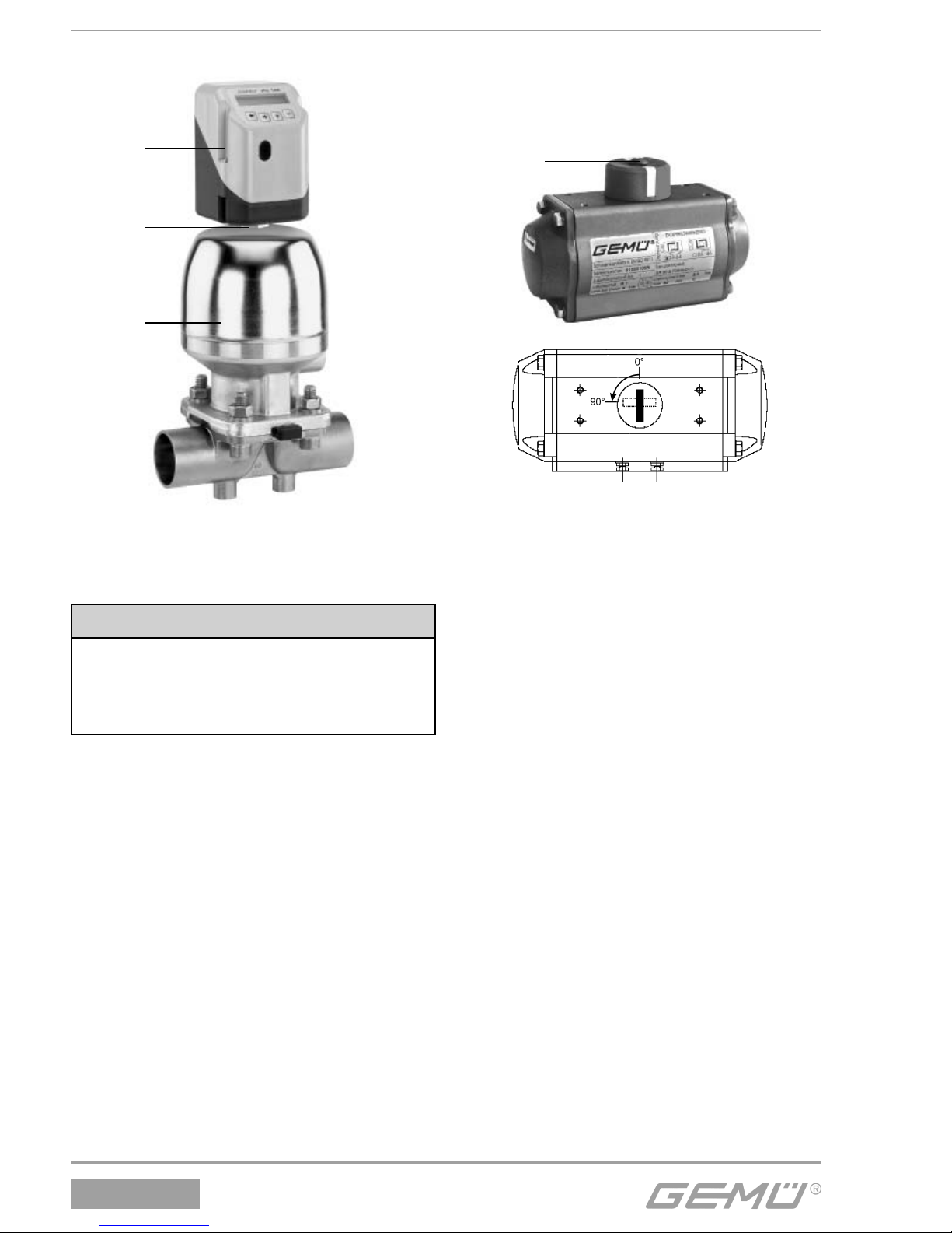
2 Mechanischer Anbau
2.1 Anbau an Hubantriebe
2.1.1 Vorbereitung des Ventilantriebs
GAntrieb muss sich in Grundstellung
(Antrieb entlüftet) befinden.
GBefindet sich im Antrieb oben eine
optische Sichtanzeige (rote Spindel),
dann diese herausziehen.
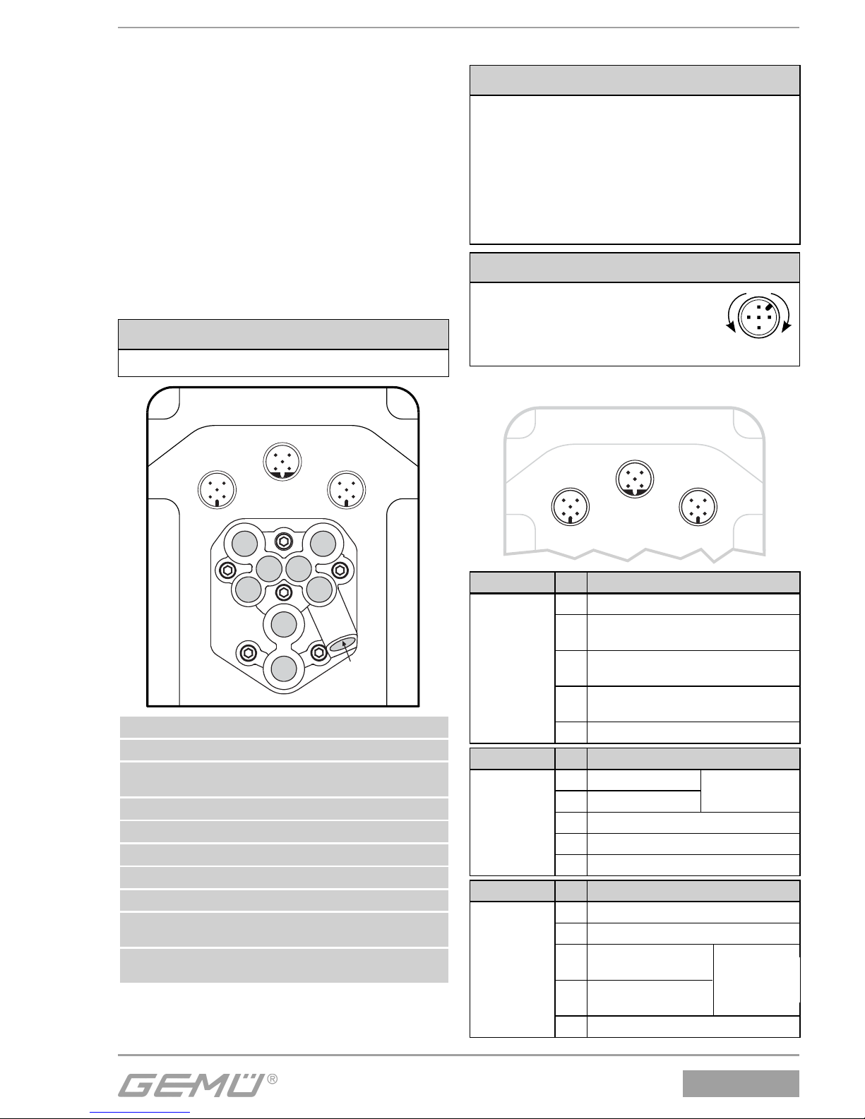
2.1.2 Komplettierung des Weggebers
Der Weggeber wird mit einem
Anbausatz 1436S01Z..., bestehend aus
Druckfeder, Betätigungsspindel und evtl.
Gewindeadapter komplettiert.
Der Anbausatz ist ventilspezifisch.
VORSICHT
Vorgespannte Feder!
®Beschädigung des Gerätes.
●Feder langsam entspannen.
VORSICHT
Eine Beschädigung der Spindel-
oberfläche kann zum Ausfall des
Weggebers führen!
1. Spindel aus Weggeber bis Anschlag
heraus ziehen.
Weggeber
2. Druckfeder über Spindel schieben.
3. Spindel an Punkt afixieren (Spindel
darf dabei nicht beschädigt werden).
Weggeber Spindel
a Druckfeder
Betätigungsspindel
4. Betätigungsspindel auf Spindel
aufschrauben.
a