IndigoVision BX series User manual

IndigoVision
8/16 Channel Encoder
BX Range
User Guide

2 User Guide - v1-Draft 1
THIS MANUAL WAS CREATED ON 2/14/2018.
DOCUMENT ID: IU-RACK-MAN011-1-DRAFT 1
Legal considerations
LAWS THAT CAN VARY FROM COUNTRY TO COUNTRY MAY PROHIBIT CAMERA SURVEILLANCE. PLEASE ENSURE THAT THE RELEVANT LAWS
ARE FULLY UNDERSTOOD FOR THE PARTICULAR COUNTRY OR REGION IN WHICH YOU WILL BE OPERATING THIS EQUIPMENT. INDIGOVISION
LTD.ACCEPTS NO LIABILITY FOR IMPROPER OR ILLEGAL USE OF THIS PRODUCT.
Copyright
COPYRIGHT © INDIGOVISION LIMITED. ALL RIGHTS RESERVED.
THIS MANUAL IS PROTECTED BY NATIONAL AND INTERNATIONAL COPYRIGHT AND OTHER LAWS. UNAUTHORIZED STORAGE,REPRODUCTION,
TRANSMISSION AND/OR DISTRIBUTION OF THIS MANUAL,OR ANY PART OF IT,MAY RESULT IN CIVIL AND/OR CRIMINAL PROCEEDINGS.
INDIGOVISION, INDIGOULTRA, INDIGOPRO,AND INDIGOLITE ARE REGISTERED TRADEMARKS OF INDIGOVISION LIMITED. CAMERA GATEWAY,
AND MOBILE CENTER ARE UNREGISTERED TRADEMARKS OF INDIGO VISION LIMITED. ALL OTHER PRODUCT NAMES REFERRED TO IN THIS
MANUAL ARE TRADEMARKS OF THEIR RESPECTIVE OWNERS.
SAVE AS OTHERWISE AGREED WITH INDIGO VISION LIMITED AND/OR INDIGO VISION, INC., THIS MANUAL IS PROVIDED WITHOUT EXPRESS
REPRESENTATION AND/OR WARRANTY OF ANY KIND. TO THE FULLEST EXTENT PERMITTED BY APPLICABLE LAWS, INDIGO VISION LIMITED
AND INDIGO VISION, INC.DISCLAIM ALL IMPLIED REPRESENTATIONS,WARRANTIES ,CONDITIONS AND/OR OBLIGATIONS OF EVERY KIND IN
RESPECT OF THIS MANUAL. ACCORDINGLY ,SAVE AS OTHERWISE AGREED WITH INDIGO VISION LIMITED AND/OR INDIGOVISION, INC., THIS
MANUAL IS PROVIDED ON AN “AS IS”, “WITH ALL FAULTS”AND “AS AVAILABLE”BASIS. PLEASE CONTACT INDIGOVISION LIMITED (EITHER BY
POST OR BY E-MAIL AT TECHNICAL.SUPPORT@INDIGOVISION.COM)WITH ANY SUGGESTED CORRECTIONS AND/OR IMPROVEMENTS TO THIS
MANUAL.
SAVE AS OTHERWISE AGREED WITH INDIGO VISION LIMITED AND/OR INDIGO VISION, INC., THE LIABILITY OF INDIGO VISION LIMITED AND
INDIGOVISION, INC.FOR ANY LOSS (OTHER THAN DEATH OR PERSONAL INJURY)ARISING AS A RESULT OF ANY NEGLIGENT ACT OR OMISSION
BY INDIGO VISION LIMITED AND/OR INDIGO VISION, INC.IN CONNECTION WITH THIS MANUAL AND/OR AS A RESULT OF ANY USE OF OR
RELIANCE ON THIS MANUAL IS EXCLUDED TO THE FULLEST EXTENT PERMITTED BY APPLICABLE LAWS.
Contact address
IndigoVision Limited
Charles Darwin House,
The Edinburgh Technopole,
Edinburgh,
EH26 0PY
8/16 Channel Encoder - BX Range

User Guide - v1-Draft 1 3
TABLE OF CONTENTS
Legal considerations 2
Copyright 2
Contact address 2
1 About This Guide 5
Safety notices 5
2 Hardware Description 7
Overview 7
Variants 7
Connections 7
Power requirements 8
Front panel 9
3 Getting Started 10
Package contents 10
Encoder 10
Additional 10
Powering up the device 10
Configuring the device 10
Configure the settings 10
Installation 11
Installing the encoder into a rack cabinet 11
4 Operations 12
Configuring the encoder 12
Reset to factory defaults 12
5 Web configuration pages 14
Preview 14
Alarm 14
Setup 14
Camera 14
Network 17
Event 20
System 23
Security 26
Info 26
6 Hardware Specification 28
Codec 28

4 User Guide - v1-Draft 1
Video 28
Audio 28
Connections 28
Binary I/O connections 29
Environment 29
Regulatory 29
8/16 Channel Encoder - BX Range

User Guide - v1-Draft 1 5
1ABOUT THIS GUIDE
This guide is written for users of the IndigoVision BX 8/16 Channel Encoder. It provides
installation and configuration information for the device variants, as well as a description of
the hardware and specifications.
Please ensure you read the instructions provided in the guide before using the device.
Safety notices
This guide uses the following formats for safety notices:
Indicates a hazardous situation which, if not avoided, could result in death or serious injury.
Indicates a hazardous situation which, if not avoided, could result in moderate injury, damage
the product, or lead to loss of data.
Indicates a hazardous situation which, if not avoided, may seriously impair operations.
Additional information relating to the current section.

6 User Guide - v1-Draft 1
1 About This Guide 8/16 Channel Encoder - BX Range

User Guide - v1-Draft 1 7
2HARDWARE DESCRIPTION
This chapter details the BX 8/16 Channel Encoder, its connections, and its weights and
dimensions.
Overview
The IndigoVision BX 8/16 Channel Encoder is an encoder designed to be used with the
company’s complete end-to-end IP Video solution.
The device encodes video, audio, and binary events allowing traditional analog CCTV
cameras (PAL and NTSC) to be integrated into an IP network.
Variants
The encoder is available in 8 and 16 Channel variants, each with the same 1U form factor.
Figure 1: BX 8/16 Channel Encoder
Metrics
The encoder has the following dimensions:
• Height: 45mm
• Width: 325mm (11in)
• Depth: 245mm (14.7in)
• Weight
• 1.25Kg (8 channel)
• 1.45Kg (16 channel)
Connections
The encoder is connected using connection sockets in the rear panel.
8 User Guide - v1-Draft 1
13
1211109
8
7654321
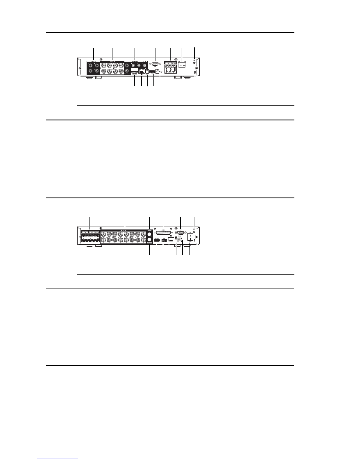
Figure 2: Rear panel (8 channel)
No. Description No. Description
1 Audio IN(5-8) 8 HDMI (not supported)
2 Video IN (1-8) 9 Ethernet
3 Audio IN (1-4) 10 RS485 A/B(camera control)
4 VGA (not supported) 11 USB2.0 (not supported)
5 Alarm I/Oconnections 12 Power (12V DC)
6 Power ON/OFF 13 Cable fastener
7 Ground screw
Table 1: Connections (8 channel)
14
1312
11109
87
654321
Figure 3: Rear panel (16 channel)
No. Description No. Description
1 Alarm I/Oconnections 8 HDMI (not supported)
2 Video IN 9 USB2.0 (not supported)
3 Audio IN (channel 1) 10 Ethernet
4 Audio IN (channels 2-16) using 15-way Audio connector 11 RS485 A/B(camera control)
5 VGA (not supported) 12 Power (12V DC)
6 Ground screw 13 Power ON/OFF
7 Audio OUT 14 Cable fastener
Table 2: Connections (16 channel)
Power requirements
The encoder has the following power requirements:
• Consumption:
• 8W (8 channel)
2 Hardware Description 8/16 Channel Encoder - BX Range

User Guide - v1-Draft 1 9
• 10W (16 channel)
• Voltage:
• 12V DC
Front panel
The encoder has several indicator lights on the front panel.
Name Description Status light Meaning
STATUS Status On The device is working normally.
HDD Hard disk drive On Internal disk is malfunctioning.
NET Network On Error detected in network connection.
POWER Power status On The device is connected to power.
Table 3: Indicator lights
8/16 Channel Encoder - BX Range 2 Hardware Description

User Guide - v1-Draft 1 10
3GETTING STARTED
This chapter describes the initial steps required to start using your BX 8/16 Channel Encoder.
Package contents
Figure 4: BX 8/16 Channel Encoder
Encoder
1. BX 8/16 Channel Encoder
Additional
• 2x Binary I/OTerminal block
• 1x Quick Start Guide
• 1x 15-way Audio connector (16 Channel variant only)
• 1x 12V DC Power supply
Powering up the device
The encoder must be powered by auxiliary power using the supplied power supply.
• Auxillary power supply
• 12V DC with a maximum power of 10 Watts
The encoder should only be powered from the specified voltage. The encoder will emit a beep
when it is powered up.
Configuring the device
Before you connect the device to your network, you must configure the device's IPaddress
and subnet mask appropriately.
Configure the settings
1. Power up the encoder and connect to a PC using an Ethernet cable.
2. Navigate to the encoder's default IP address using a web browser, and enter the
default user name.

11 User Guide - v1-Draft 1
Default Username Admin
Default IP Address 10.5.1.10
Default Subnet Mask 255.0.0.0
Default Gateway 10.0.0.1
Table 4: Default network settings
3. When prompted, enter a secure password for the Admin user. Please note this
password carefully.
The admin password must be set before the encoder can be used in Control Center.
If the admin password is forgotten, the hardware reset procedure must be performed to
regain access to the encoder.
►For more information, refer to see "Reset to factory defaults" on page 12
4. Enter the NTP server and port on the Setup > System > General >Date &Time
menu.
5. Enter a new IP address and subnet mask on the Setup > Network > TCIP/IP menu.
6. Select the video standard for your region using the Video Standard option on the
Setup > System > General menu.
Choose PAL for countries with 50Hz power frequency and NTSC for countries with
60Hz power frequency.
Installation
This section details how to install the BX 8/16 Channel Encoder.
Installing the encoder into a rack cabinet
1. Mount the encoder in the rack using a rack mount kit (IndigoVision part code 130079)
according to the instructions in the supplied Installation Guide.
When installing your BX 8/16 Channel Encoder in a rack cabinet, please consider the
following:
•Elevated Operating Ambient — If installed in a closed or multi-unit rack assembly,
the operating ambient temperature of the rack environment may be greater than room
ambient. Therefore, consideration should be given to installing the equipment in an
environment compatible with the specified maximum ambient temperature (Tma) of
the unit.
•Reduced Air Flow — Installation of the equipment in a rack should be such that the
amount of air flow required for safe operation of the equipment is not compromised. To
facilitate this, an air gap of at least 6cm on both sides of the unit is recommended.
•Mechanical Loading — Mounting of the equipment in the rack should be such that a
hazardous condition is not achieved due to uneven mechanical loading.
•Circuit Overloading — Consideration should be given to the connection of the
equipment to the supply circuit and the effect that overloading of the circuits might
have on overcurrent protection and supply wiring. Appropriate consideration of
equipment nameplate ratings should be used when addressing this concern.
•Reliable Earthing — Reliable earthing of rack-mounted equipment should be
maintained. Particular attention should be given to supply connections other than
direct connections to the branch circuit (e.g. use of power strips).
3 Getting Started 8/16 Channel Encoder - BX Range

User Guide - v1-Draft 1 12
4OPERATIONS
This chapter describes common tasks required for the operation of the BX 8/16 Channel
Encoder.
Configuring the encoder
You can access the encoder configuration pages using the IP address of the encoder.
Alternatively, you can access these pages through IndigoVisionControlCenter.
This functionality is only available if you have administrator permissions.
1. In Setup view, select the encoder you want to configure.
2. Select the Configure tab, and enter a valid user name and password if required.
►For more information, see "Web configuration pages" on page 14
Reset to factory defaults
You can reset the encoder settings to factory defaults using the following methods while the
encoder is powered:
• Go to Setup > System > Default on the encoder's Configuration pages, and enter the
chosen credentials.
If a full hardware reset is required, for example, if you have forgotten the admin password,
then please contact IndigoVision Technical Support for more information.

13 User Guide - v1-Draft 1
4 Operations 8/16 Channel Encoder - BX Range

User Guide - v1-Draft 1 14
5WEB CONFIGURATION PAGES
To access the Web Configuration pages, enter the IP address of your device into a web
browser. The Home menu is displayed.
IndigoVision products support Microsoft ®Internet Explorer (version 6 or higher
recommended).
To access any of the other configuration pages, click the required option in the menu on the
left of each page.
Preview
This page allows you to Preview and control the cameras connected to each Channel of the
BX 8/16 Channel Encoder.
Use the selectors to the left of the main panel to choose the Channels and Streams to
preview. You can also use the selectors below the main panel to control the layout.
Select an appropriate Stream in the main panel, and use the controls to the right of the main
panel to control a PTZ camera. You can also preview changes to the Image Setup and the
Alarm Outputs available on the encoder.
Alarm
This page allows you to check the Alarms which have been triggered on the BX 8/16 Channel
Encoder.
Use the Alarm list to view information about recently triggered Alarms. You can use the
checkboxes to the left of the Alarm list to filter it.
Setup
These pages allow you to configure the setup options for the BX 8/16 Channel Encoder.
Camera
These pages allow you to configure the Camera image, encoding, and channel information for
the BX 8/16 Channel Encoder.

15 User Guide - v1-Draft 1
Image
Use this page to configure the image conditions for each encoder channel on the BX 8/16
Channel Encoder.
•Channel — Select the required Channel from the drop-down to configure the image
conditions.
You can use the preview image on the left to verify the Channel input.
•Cable Type — Select the connected cable type for the encoder Channel.
•Period — Select the checkbox and enter time ranges to enable the configuration of
different image conditions depending on time of day.
Use the Saturation,Brightness,Contrast,Hue and Sharpness sliders to adjust the image
conditions as required. The preview image shows the effect of the adjustments made.
You can also use the Color Mode dropdown to choose from preset image conditions.
•Customized — Click to access the image conditions for the Customized presets.
Choose the required preset and adjust the image conditions as required. The preview
image shows the effect of the adjustments made.
Click Save to save over the selected preset.
Click Default to return to defaults for that preset.
Click Back to return to the main page.
Use the Image Enhance and NR(Noise Reduction) sliders to further enhance the image until
the image is as required for the selected Channel.
Click Default to return all image conditions for the selected Channel to the system defaults.
Click Cancel to discard all image condition changes made to the selected Channel.
Encode
Use this page to configure the encoding settings for the BX 8/16 Channel Encoder.
On the Encode tab, you can select the required input Channel and configure the video and
audio encoding settings:
•Channel No. — Select the encoder Channel to configure.
•Code-Stream Type (under Main Stream) — Select the stream type to configure.
This allows different encoding settings to be used when bandwidth is high, or during
the specified type of event:
•Regular
•Alarm
•MD (Motion Detection)
•Video Enable (under Sub Stream) — Select to enable encoding settings to be used
when bandwidth is low.
Configure the settings for the selected Channel using the following options for the Main
Stream, and Sub Stream if enabled:
•Compression — Select the video encoding standard to be used:
•H.264H: High Profile (high compression, lower bandwidth)
•H.264: Main Profile (standard compression)
•H.264B: Baseline Profile (low compression, higher bandwidth)
•Resolution — Select the resolution of the video stream.
•Bitrate Type — Select the type of bitrate to be used.
5 Web configuration pages 8/16 Channel Encoder - BX Range

User Guide - v1-Draft 1 16
• Variable
• Constant
•Image Quality (for Variable Bitrate only) — Select what type of image quality is to be
used for video, on a scale of 1 to 6.
•Frame Rate — Select how often the video stream is updated. A high frame rate is
useful for high movement in the video stream. However this requires more bandwidth.
•Bitrate — Select the maximum bitrate for video streams. Range 32-4096 Kbps.
•I-Frame Interval — Enter how often a full frame of video is transmitted. A lower I-
frame interval provides smoother rewind on recordings but requires more bandwidth
and storage.
•Audio Enable — Select this checkbox to enable audio in the stream and configuration
of the audio settings.
•Audio Format — Select the audio encoding format to be used.
•Audio Source — Select the audio source for the stream.
On the Overlay tab, you can enable and configure Overlays on a video stream:
•Channel — Select the encoder Channel to configure.
•Privacy Mask — Select the Enable checkbox, and click Set to configure opaque
privacy masks over the image.
Right-click and drag on the preview image to select areas to be masked.
•Channel Display — Select the checkbox, and click Set to display the Channel
number, or a configurable label, over the image.
Enter a label in the text field shown and drag the indicator over the preview image to
the required location.
•Time Display — Select the checkbox, and click Set to display the current time over
the image.
Drag the indicator over the preview image to the required location.
Click Copy and select a destination from the popup to copy all settings to the selected
Channel.
Click Refresh to undo the changes you have made in this page.
Click Default to restore all fields in the page to their default settings.
Click Save to apply any changes you have made.
Camera Name
Use this page to configure the naming of each camera connected to the BX 8/16 Channel
Encoder.
Enter any required camera name changes to the appropriate Channel input fields on the page.
Click Refresh to undo the changes you have made in this page.
Click Default to restore all fields in the page to their default settings.
Click Save to apply any changes you have made.
Camera Type
Use this page to configure the Camera Type settings for the BX 8/16 Channel Encoder.
8/16 Channel Encoder - BX Range 5 Web configuration pages

17 User Guide - v1-Draft 1
For most cameras, the BX 8/16 Channel Encoder automatically detects the signal input type
(AUTO). If difficulties are encountered and the encoder cannot detect the input type, you can
configure this manually.
Select the signal input type for each Channel using the checkbox grid, or alternatively use the
checkbox at the top of each column to select that input type for all Channels:
•AUTO
•CVI
•AHD
•CVBS
•OTHER
Click Refresh to undo the changes you have made in this page.
Click Default to restore all fields in the page to their default settings.
Click Save to apply any changes you have made.
Network
These pages allow you to configure the Network settings for the BX 8/16 Channel Encoder.
TCP/IP
Use this page to configure the TCP/IP settings for the BX 8/16 Channel Encoder.
•Default Card — Select a network card from the drop-down.
•IP Version — Select an IP version from the drop-down.
•MAC Address — Enter the Media Access Control address for the BX 8/16 Channel
Encoder.
•IP Address — Enter the IPAddress.
•Subnet Mask — Enter the Subnet Mask.
•Default Gateway — Enter the Default Gateway.
•Preferred DNS — Enter the preferred domain name server.
•Alternate DNS — Enter an alternate domain name server.
•MTU — Enter the maximum transmission unit. This is the maximum size of a packet
which is sent from the BX 8/16 Channel Encoder.
Click Refresh to undo the changes you have made in this page.
Click Default to restore all fields in the page to their default settings.
Click Save to apply any changes you have made.
Connection
Use this page to configure the connection settings for the BX 8/16 Channel Encoder.
•Max Connection — Enter the maximum number of connections from the BX 8/16
Channel Encoder to the server. This cannot be more than 128.
Assign a connection port for the BX 8/16 Channel Encoder:
•TCPPort
•UDPPort
•HTTPPort
•HTTPS Port
5 Web configuration pages 8/16 Channel Encoder - BX Range

User Guide - v1-Draft 1 18
•RTSPPort
Click Refresh to undo the changes you have made in this page.
Click Default to restore all fields in the page to their default settings.
Click Save to apply any changes you have made.
HTTPS
Use this page to configure the HTTPS settings for the BX 8/16 Channel Encoder.
•Create — Select this option to create a new HTTPS server certificate.
•Create Certificate Request — Select this option to create a new HTTPS server
certificate request.
•Install Signed Certificate — Select Browse or Upload to install a signed HTTPS
server certificate.
•Created Request — Select Properties to view the properties of the HTTPS server
certificate request. Select Remove to remove the certificate request.
•Certificate Installed — View information and attributes of the installed HTTPS server
certificate.
DDNS
Use this page to configure the Dynamic Domain Name Server (DDNS) settings for the BX
8/16 Channel Encoder.
•Enable — Select this option to enable DDNS for the BX 8/16 Channel Encoder.
•DDNS Type — Select the type of DDNS which you want the BX 8/16 Channel
Encoder to use from the drop-down.
When you select a DDNS type, the BX 8/16 Channel Encoder displays a set of fields
for which you must enter values.
If you select No-IP DDNS,CN99 DDNS, or Dynds DDNS, the following fields are
displayed:
•Host IP
•Domain Name
•Username
•Password
•Interval
Click Refresh to undo the changes you have made in this page.
Click Default to restore all fields in the page to their default settings.
Click Save to apply any changes you have made.
SMTP(Email)
Use this page to configure email alerts to be sent from the BX 8/16 Channel Encoder to an
email address when an alarm is triggered.
•Enable — Select this option to enable email alerts.
•SMTP Server — Enter the mail server from which you want the BX 8/16 Channel
Encoder to send the email.
•Anonymous — Select this option if you do not want the email to display the login
details with which the BX 8/16 Channel Encoder access the mail server.
•Username,Password, and Sender — Enter the login details with which the BX 8/16
Channel Encoder accesses the mail server.
8/16 Channel Encoder - BX Range 5 Web configuration pages

19 User Guide - v1-Draft 1
•Encrypt Type — Select the type of encryption which you want the email to use. By
default, this is NONE, and the email is unencrypted.
•Subject — Enter the subject to appear in the email.
•Receiver — Select the recipients to whom the BX 8/16 Channel Encoder sends the
email.
•Interval — Enter the period of time in seconds after the alarm is triggered before the
BX 8/16 Channel Encoder sends the email.
•Health Enable — Select this option if you want the BX 8/16 Channel Encoder to send
a second email after the alarm has been triggered, after a longer period of time than the
first. Enter the period of time in minutes.
Click Email Test to send a test email.
Click Refresh to undo the changes you have made in this page.
Click Default to restore all fields in the page to their default settings.
Click Save to apply any changes you have made.
UPnP
Use this page to configure the UPnP (Universal Plug and Play) settings for the BX 8/16
Channel Encoder used for the sharing of network services.
•Enable/Disable — Use these options to enable or disable PAT(Port Address
Translation). When enabled, additional Status information is displayed, for example,
for UPnP search requests and responses.
•Port Mapping List — Shows all currently available port mappings and the configured
values for each mapping.
•Modify — Click the icon in this column to modify the configured values for the
selected port mapping.
•Delete — Click the icon in this column to delete the selected port mapping from the
list.
Click Add to add port mappings to the list, entering the required information on the service in
the dialog displayed.
Click Refresh to undo the changes you have made in this page.
Click Default to restore all fields in the page to their default settings.
Click Save to apply any changes you have made.
Multicast
Use this page to configure Multicast of video or audio channels from cameras connected to
the BX 8/16 Channel Encoder, allowing the required channel to be addressed to a group of
destinations simultaneously.
•Encode and Channel — Select the channel type and input channel on the BX 8/16
Channel Encoder to be sent using Multicast.
•Main Stream — Configure the main stream to be sent using Multicast for the selected
input channel.
•Enable — Select this option to enable the Main Stream to be sent for the channel.
•Main Stream — Enter the IP address to be used for sending the Main Stream using
Multicast.
•Port — Enter the port number to be used for sending the Main Stream using
Multicast.
5 Web configuration pages 8/16 Channel Encoder - BX Range

User Guide - v1-Draft 1 20
•Sub Stream — Configure the Sub Stream to be sent using Multicast for the selected
input channel.
•Enable — Select this option to enable the Sub Stream to be sent for the channel.
•Sub Stream — Enter the IP address to be used for sending the Sub Stream using
Multicast.
•Port — Enter the port number to be used for sending the Sub Stream using
Multicast.
Click Refresh to undo the changes you have made in this page.
Click Default to restore all fields in the page to their default settings.
Click Save to apply any changes you have made.
Event
These pages allow you to configure the Event detection and Alarm settings for the BX 8/16
Channel Encoder.
Video Detection
Use this page to configure the Video Detection settings for the BX 8/16 Channel Encoder.
On the Motion Detection,Video Loss,Video Tamper, and Diagnosis tabs, you can setup
actions to be taken when motion, loss of video, tampering or camera errors are detected by
the encoder.
•Enable — Select the checkbox to enable detection, and select a Channel for
configuration from the dropdown.
Click Set to configure the types and severity of error which should trigger a detection
on that Channel, using the checkboxes and sliders in the popup displayed (Diagnosis
only).
•Period — Click Set to configure the active time periods on the selected Channel.
You can set a maximum of 6 active periods for each day. Configure the active periods
using the visual display with the checkboxes and entry fields below the display. In the
visual display, green bars indicate the active periods for each day of the week.
• Click Set next to the day where you want to configure the active periods.
The day being configured is highlighted in red and the checkbox for that day is
automatically selected below the display.
• Select additional checkboxes or All below the display to configure the same active
periods for several days.
• Click on a green bar for that day to remove it, or click and drag in the area below the
bar to add an active period.
As you configure the active periods, they are reflected in the entry fields below the
visual display.
Click Default to restore all active periods to their default settings.
Click Save to apply any changes you have made.
Click Cancel to cancel the changes you have made to active periods.
•Anti-dither — Enter a time in seconds of 0to 600, in which the encoder will only
recognize a single detection.
•Sensitivity— Use the dropdown to configure the tamper sensitivity from 1to 6where
higher values represent increased sensitivity (Video Tamper only).
•Region— Click Set to configure the image regions where detection is used on the
selected Channel.
8/16 Channel Encoder - BX Range 5 Web configuration pages
Table of contents
Other IndigoVision Media Converter manuals


