6
DISTRIBUTION UNIT DA-240
INPUT CONNECTION TO THE DA-410
The distribution unit DA-240 input connection is made by means of four pigtail cables of
PHOENIX connectors and XLR male connectors, one by each DA-410 input signal: (A-L with A-L, A-R
with A-R, B-L with B-L and B-R with B-R). The cable and the connection are described in the following
graph:
PHOENIX CONECTOR XLR MALE CONNECTOR
DA-240 DA-410
A-L, A-R, B-L or B-R. A-L, A-R, B-L or B-R.
OUTPUT CONNECTION FROM THE DA-410
The distribution unit DA-240 output connection is made by means of ten pigtail cables of
PHOENIX connectors and XLR female connectors, one by each DA-410 output signal: (1 with 1, 2 with
2, … and 10 with 10). The cable and the connection are described in the following graph:
PHOENIX CONNECTOR XLR FEMALE CONNECTOR
DA-240 DA-410
1, 2, 3, ... , 10. 1, 2, 3, ... , 10.
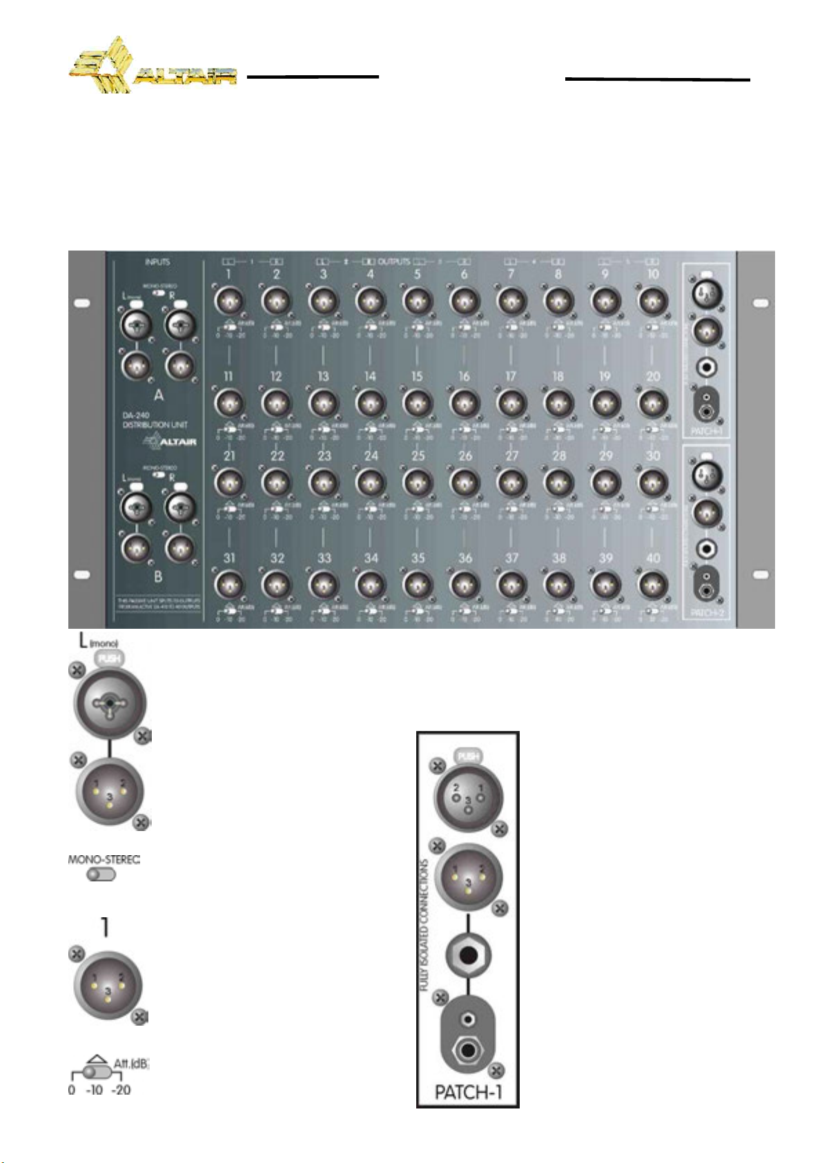
INPUT CONECTION
The distribution unit input signals is carried out through four COMBO™ or four XLR-
3-32 male connectors, two per stereo channel. Each input internally has one COMBO™
and an XLR-3-32 connector wired in parallel. The input connections are balanced, with
a nominal impedance of 5 kΩ(2,5kΩunbalanced) with the input set-up in line mode
and 2 kΩ(1kΩunbalanced) with the input set-up in mic mode. (NOTE: These impedance
values correspond to the DA-410 unit, since the inputs are connected directly).
The COMBO™ connectors accept XLR female or Jack ¼”, reason why in the
following table is to the correspondence of the pins of connectors XLR as well as of a
Jack ¼” .
XLR-3-31/XLR-3-32 JACK ¼”
PIN 1 GND SLEEVE GND
PIN 2 HOT (+) TIP HOT (+)
PIN 3 COLD (-) RING COLD (-)
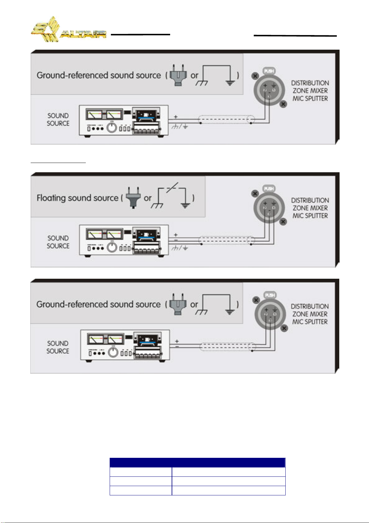
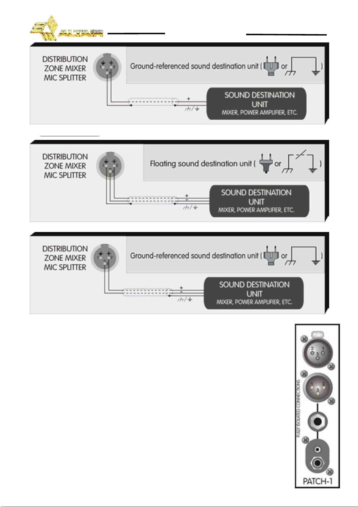
The input connection depends on two factors, the first is the type of input signal balanced or
unbalanced, and the second the ground configuration of the sound source (floating or ground-
referenced). The next pictures show some of the different possibilities of connection, relying on the
type of input signal, balanced or unbalanced and according to the ground configuration of the
equipment (floating or ground-referenced).
NOTE: All the inputs and outputs of the unit accept phantom power.
In the next diagrams, we use the following symbols:
Sound source with mains cord without ground connection.
Sound source with mains cord with ground connection.
IP.
RING.
SLEEVE.