Indumicro IMP-A151[G]T User manual

Industrial Panel PCs
IMP-A1x1 Series
User Manual

2
Warning!
___________________________________
This equipment generates, uses and can radiate radio frequency energy and if not installed and
used in accordance with the instructions manual may cause interference to radio communications.
It has been tested and found to comply with the limits for a Class A computing device pursuant to
FCC Rules, which are designed to provide reasonable protection against such interference when
operated in a commercial environment. Operation of this equipment in a residential area is likely
to cause interference in which case the user at his own expense will be required to take whatever
measures may be required to correct the interference.
Disclaimer
This information in this document is subject to change without notice. In no event shall
Indumicro.com be liable for damages of any kind, whether incidental or consequential,
arising from either the use or misuse of information in this document or in any related
materials.
Electric Shock Hazard – Do not operate the machine with its back cover removed. There are
dangerous high voltages inside.
___________________________________

Table of Contents
Chapter 1: System description
1.1 Specifications .............................................................................................................................. 1
1.2 Features of the IMP-A1x1 series ................................................................................................. 2
Chapter 2: Configuring the system
2.1 Installing a PCI add-on card ........................................................................................................ 3
2.2 Wiring diagrams serial ports ........................................................................................................ 4
Chapter 3: Touch screen configuration
3.1 Configuring a resistive touch screen ........................................................................................... 5
Chapter 4: Dimension drawings
4.1 Dimension drawing IMP-A151[G]T ............................................................................................ 17
4.2 Dimension drawing IMP-A171[G]T ............................................................................................ 18
4.3 Dimension drawing IMP-A191T ................................................................................................ 19

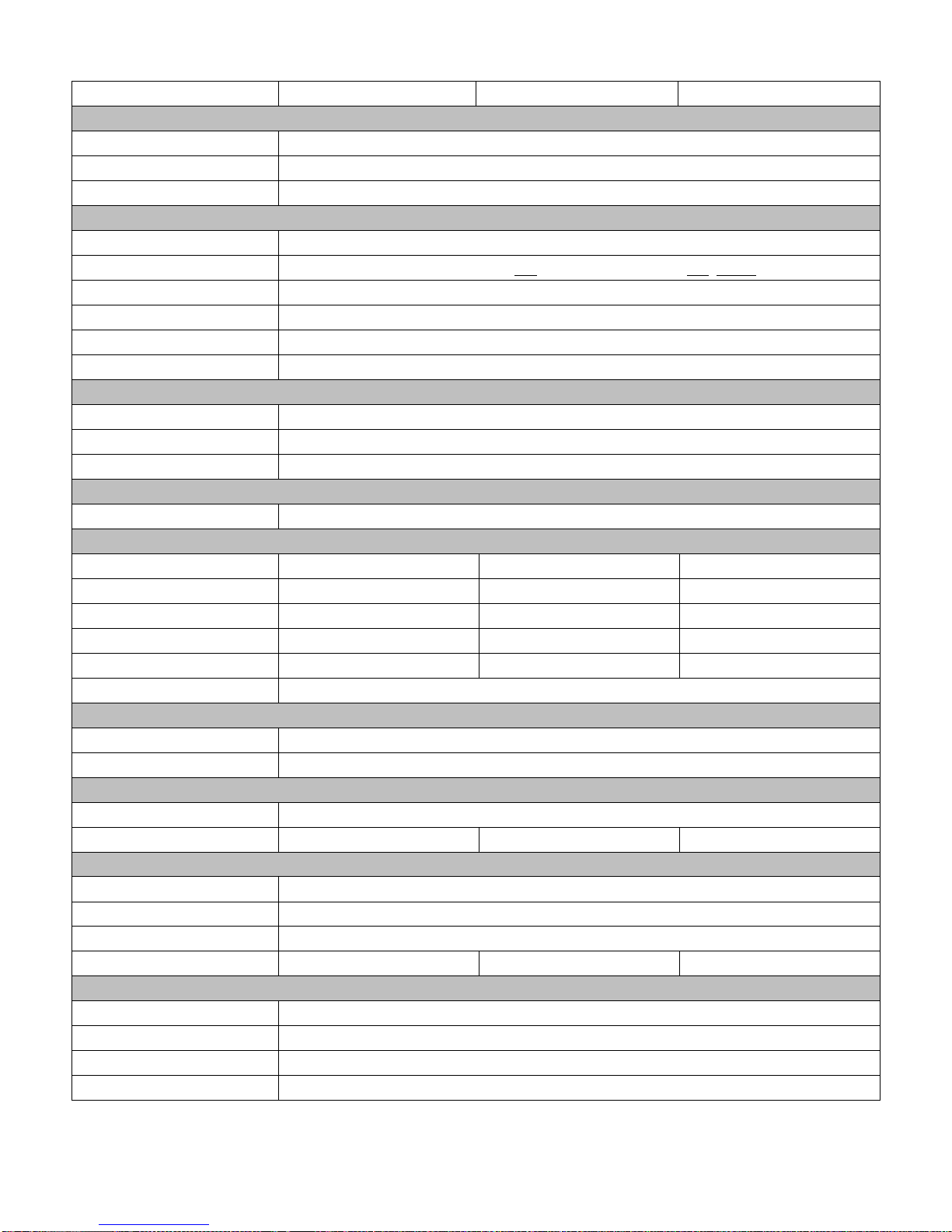
1.1 Specifications
Model IMP-A151[G]T IMP-A171[G]T IMP-A191T
System
CPU Intel®Atom™ Cedar View D2550 1.8GHz Dual Core Processor
System chipset Intel NM 10 Express
System memory 2 x 204-pin DDR3 SO-DIMM 800/1066MHz, up to 4GB
I/O Ports
USB 4 x USB 2.0 type A
Serial / Parallel 1 x RS-232, 1 x RS-232/422/485 and 1 x RS-422/485 (default)
Audio 1 x MIC-in, 1 x Line-out
External display 1 x VGA
LAN 2 x GbE
Other 1 x 2 pin remote power switch
Storage Space
HDD 1 x 320 GB SATA HDD
Card reader 1 x Externally accessible CompactFlash slot
Supported OS Windows XP Pro, Windows Standard Embedded 7 (32bit)
Expansion
Expansion slots 1 x PCI slot
Display
Display type 15” TFT-LCD 17” TFT-LCD 19” TFT-LCD
Max. resolution 1024x768 1280x1024 1280x1024
Max. color 262K 16.7M 16.7M
Luminance (cd/m2) 40 350 350 2
View angle 160° / 160° 170° / 170° 170° / 160°
Backlight lifetime 50,000 hrs
Touch Screen
Type Analog resistive on ‘T’ models, GFG on ‘GT’ models
Light transmission 80% for ‘T’ models / 90% for ‘GT’ models
Power
Input voltage DC 9~32V
Power consumption 33.2W 47.6W 48.1W
Mechanical
Construction Steel front and cover
IP rating IP65 front panel
Mounting Panel mount / VESA 75
Dimensions (w x h x d) 410 x 310 x 94.8mm 439 x 348 x 94.3mm 484 x 400 x 94.3mm
Environmental
Operating temperature 0~50°C
Storage temperature -20~60°C
Storage humidity 10 to 90% @ 40°C, non- condensing
Certification CE / FCC Class A
IMP-A1x1 User Manual 1
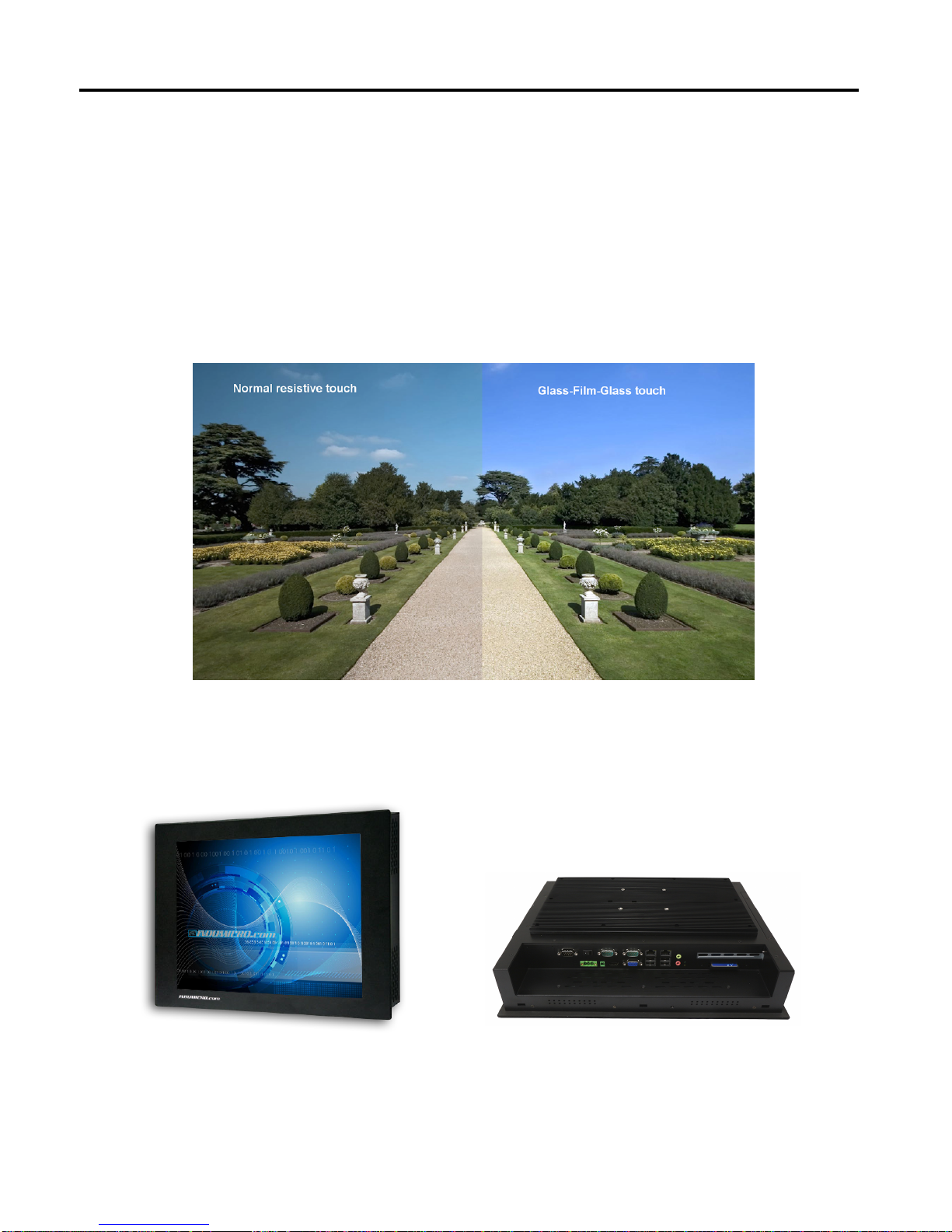
1.2 Fea tures of the IMP-A1x1 series
The IMP-A151/A171/A191 are fanless / compact panel-mount industrial PCs, which come with a 15"
(luminance of 400 cd/m²), 17" (luminance of 350 cd/m²) or 19" (luminance of 350 cd/m²) TFT LCD.
They are powered by an Intel®Atom D2550 1.8GHz processor.
®
These industrial panel PCs also feature a PCI expansion slot, three COM ports, four USB 2.0 ports,
one 2.5” HDD drive, a wide range DC 11~32V power input, etc.
The 'T' models are equiped with an analog resistive touch screen while the 'GT' models come with a
GFG (Glass-Film-Glass) touch screen.
GFG touch screens are not only resistant to scratch and abrasion but also to most of the chemicals.
Apart from that, glass is transparent and does not impair the brilliance of the picture at all.
Front and rear view of the IMP-A171
Chapter 1: System description
IMP-A1x1 User Manual 2

There are 2 screws to open the cover giving
you access to the PCI expansion slot.
Shown in the picture is the PCI expansion
slot as circled. It can be inserted with any
half-size PCI add-on card.
(In this case the entire back cover of the
Panel PC is removed to give you a clear
picture of the position the PCI slot)
Slide the PCI add-on card into the slot.
Carefully push the add-on card into the rail
of the slot.
After placing the add-on card tighten the
screw as circled.
Close the chassis in the same way as it was
opened.
3
Chapter 2: Configuring the system
2.1 Installing a PCI add-on card
IMP-A1x1 User Manual
Chapter 2: Configuring the system
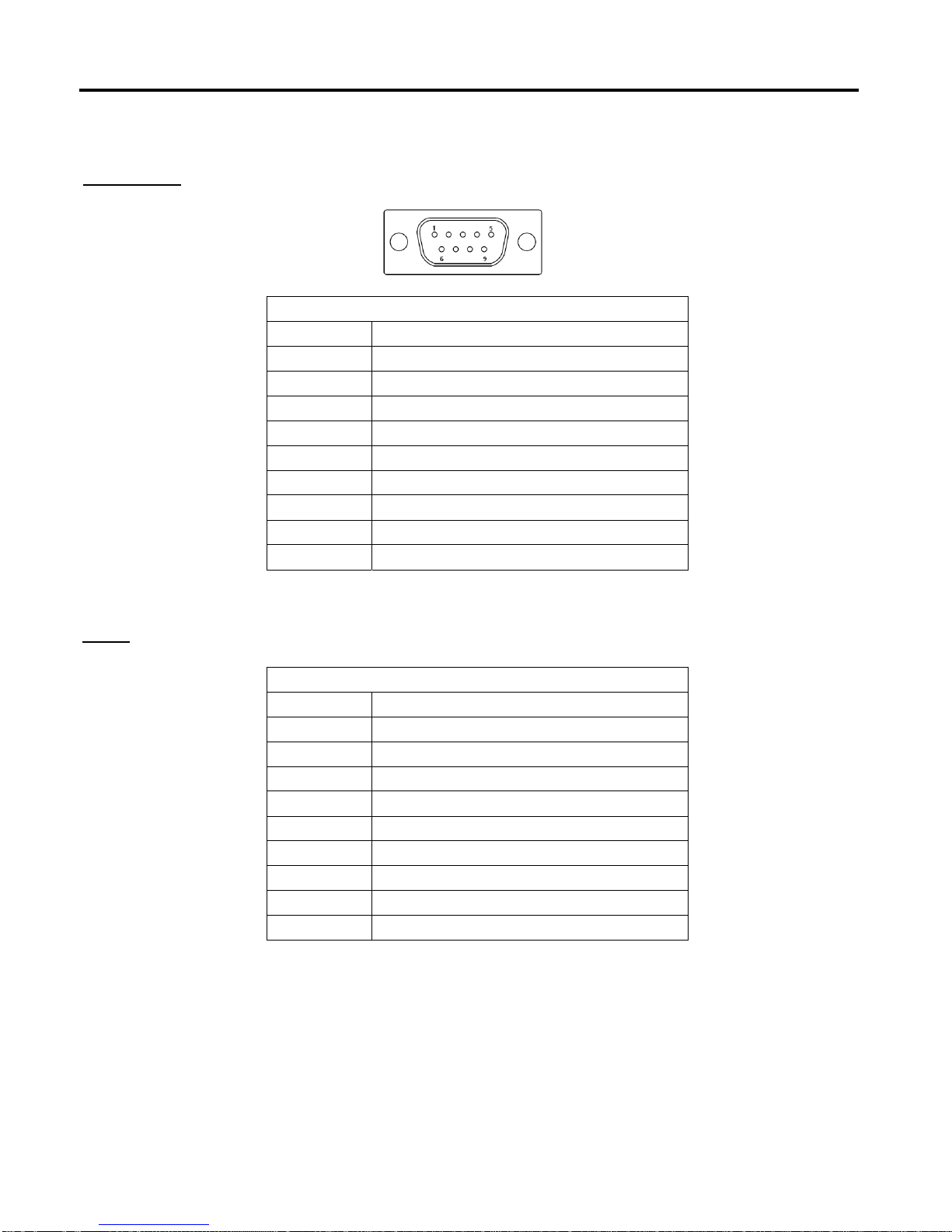
2.2
Wiring diagrams serial ports
COM1/COM2
RS-232
Pin# Signal Name
1 DCD (Data Carrier Detect)
2 RXD (Received Data)
3 TXD (Transmit Data)
4 DTR (Data Terminal Ready)
5 Ground
6 DSR (Data Set Ready)
7 RTS (Request To Send)
8 CTS (Clear To Send)
9 RI (Ring Indicator)
RS-422/485
Pin# Signal Name
1 422_RX+
2 422_RX-
3 422_TX- / 485-
4 422_TX+ / 485+
5 Ground
6 NC
7 NC
8 NC
9 NC
COM3
4
IMP-A1x1 User Manual
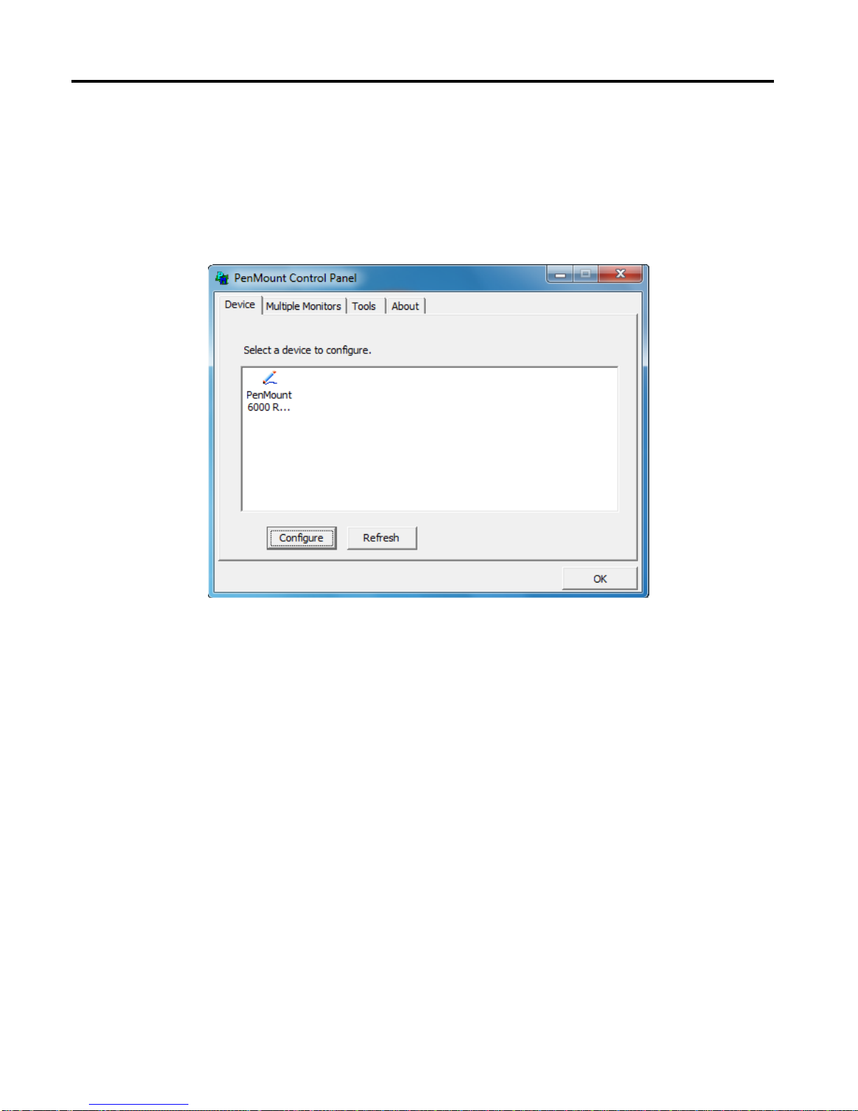
PenMount Control Panel
The functions of the PenMount Control Panel are Device, Multiple Monitors ,Tools and About,
which are explained in the following sections.
Device
In this window, you can find out that how many devices are detected on your system.
Calibrate
This function offers two ways to calibrate your touch screen. ‘Standard Calibration’ adjusts most
touch screens. ‘Advanced Calibration’ adjusts aging touch screens.
Standard Calibration Click this button and arrows appear pointing to red squares. Use your
finger or stylus to touch the red squares in sequence. After the fifth red
point calibration is complete. To skip, press ‘ESC’.
Advanced Calibration Advanced Calibration uses 4, 9, 16 or 25 points to effectively calibrate
touch panel linearity of aged touch screens. Click this button and touch
the red squares in sequence with a stylus. To skip, press ‘ESC’.
3.1 Configuring the touch screen
Chapter 3: Touch Screen configuration
5
IMP-A1x1 User Manual
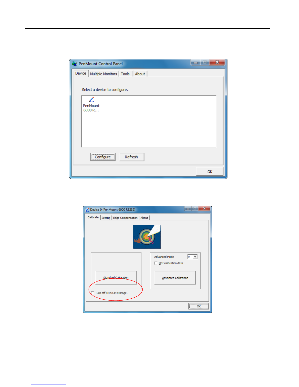
To calibrate your touch screen:
1. Please select a device then click “Configure”. You can also double click the device too.
2. Click “Standard Calibration” to start calibration procedure.
Chapter 3: Touch Screen configuration
6
IMP-A1x1 User Manual
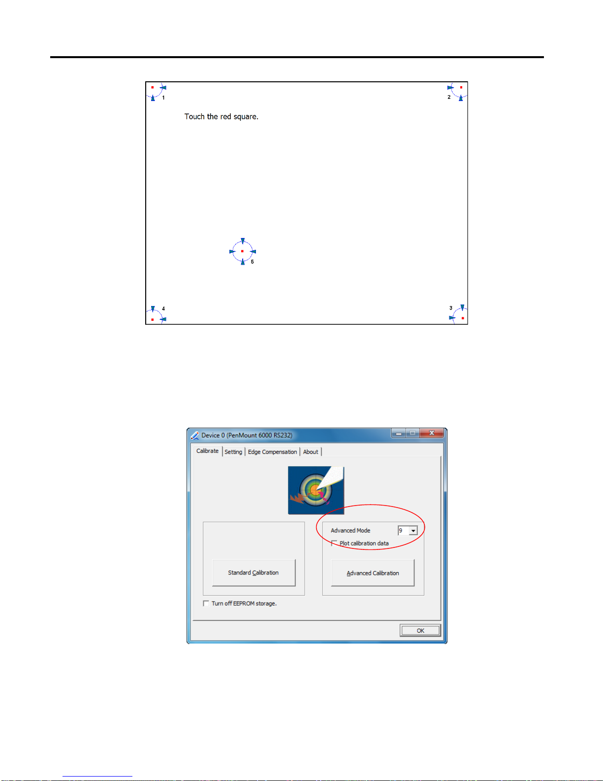
NOTE: The older the touch screen, the more Advanced Mode calibration points you need for an
accurate calibration. Use a stylus during Advanced Calibration for greater accuracy. Please follow
the step as below:
3. Come back to “PenMount Control Panel”, select Device to calibrate, then click
Advanced Calibration.
NOTE: It is recommended to use a stylus during Advanced Calibration for greater accuracy.
Chapter 3: Touch Screen configuration
7
IMP-A1x1 User Manual

Plot Calibration Data Check this function to have touch panel linearity comparison graph
appear when you finish Advanced Calibration.
The black lines reflect the ideal linearity assumed by Penmount’s
application program while the blue lines show the approximate linearity
calculated by Penmount’s application program as the result of user’s
execution of Advanced Calibration.
Turn off EEPROM
storage This function disables the write-in of calibration data in the controller.
This function is enabled by default.
Chapter 3: Touch Screen configuration
8
IMP-A1x1 User Manual

Setting
Operation Mode
Mouse Emulation This operating mode will send left button down function when user
presses, and left button up function when user release its touch.
Click On Touch This operating mode will send a mouse click only on user’s touch.
Dragging is disabled in this mode.
Pen Input Emulation When using “Pen Input Emulation”, the PenMount device driver will not
send left mouse button right away, therefore, it is recommended to use
this mode with the “press and hold” right mouse button emulation, it will
be able to activate right mouse function on “Start Menu” and other utility.
Click On Release This operation mode will send a mouse click when user release its touch
operation. This feature works well when browsing certain web pages.
NOTE: The actual mouse functions generated by the above operating modes can be viewed from the
PenMount “DRAW” utility.
Chapter 3: Touch Screen configuration
9
IMP-A1x1 User Manual

10
Beep Sound
Enable Beep Sound Turns beep function on or off.
Beep on pen down Beep occurs when pen comes down.
Beep on pen up Beep occurs when pen is lifted.
Beep on both Beep occurs when pen comes down and when it’s lifted.
Beep Frequency Modifies sound frequency.
Beep Duration Modifies sound duration.
Cursor Stabilizer
Enable this function to prevent cursor shake.
Use press and hold as right click
Set the time and area as needed.
Edge Compensation
The "Edge Compensation" function is used to optimize the cursor accuracy on the edges.
It is only supported by "Advanced Calibration", not for "Standard Calibration".
Chapter 3: Touch Screen configuration
IMP-A1x1 User Manual

About
This panel displays information about the PenMount controller and driver version.
Chapter 3: Touch Screen configuration
11
IMP-A1x1 User Manual

Multiple Monitors
Multiple Monitors support from two to six touch screen displays for one system.
The PenMount drivers for Windows 2000/XP support Multiple Monitors. This function supports from
two to six touch screen displays for one system. Each monitor requires its own PenMount touch
screen control board, either installed inside the display or in a central unit. The PenMount control
boards must be connected to the computer COM ports via the RS-232 interface. Driver installation
procedures are the same as for a single monitor. Multiple Monitors support the following modes:
Windows Extends Monitor Function
Matrox DualHead Multi-Screen Function
nVidia nView Function
NOTE: The Multiple Monitor function is for use with multiple displays only. Do not use this function if
you have only one touch screen display. Please note once you turn on this function the
rotating function is disabled.
Enable the multiple display function as follows:
1. Check the Enable Multiple Monitor Support box; then click Map Touch Screens to assign
touch controllers to displays.
Chapter 3: Touch Screen configuration
12
IMP-A1x1 User Manual

2. When the mapping screen message appears, click OK.
3. Touch each screen as it displays “Please touch this monitor”. Following this sequence and
touching each screen is called mapping the touch screens.
4. Touching all screens completes the mapping and the desktop reappears on the monitors.
5. Select a display and execute the “Calibration” function. A message to start calibration appears.
Click OK.
Chapter 3: Touch Screen configuration
13
IMP-A1x1 User Manual
6. “Touch this screen to start its calibration” appears on one of the screens. Touch the screen.
7. “Touch the red square” messages appear. Touch the red squares in sequence.
8. Continue calibration for each monitor by clicking Standard Calibration and touching the red
squares.
NOTES:
1. If you use a single VGA output for multiple monitors, please do not use the Multiple Monitor
function.Just follow the regular procedure for calibration on each of your desktop monitors.
2. The Rotating function is disabled if you use the Multiple Monitor function.
3. If you change the resolution of display or screen address, you have to redo Map Touch
Screens, so the system understands where the displays are.
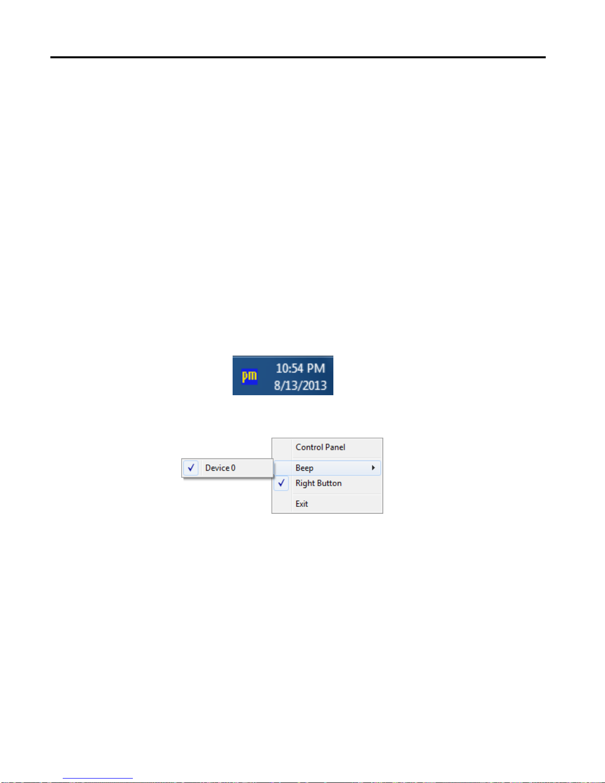
PenMount Monitor Menu Icon
The PenMount monitor icon (PM) appears in the menu bar of Windows 2000/XP/7 system when you
turn on PenMount Monitor in PenMount Utilities.
The PenMount Monitor has the following functions
Control Panel Opens the Control Panel window.
Beep Set Beep function for each device.
Right Button When you select this function a mouse icon appears on the desktop.
Click this icon to switch between right and left button functions.
Exit Exits the PenMount Monitor function.
Chapter 3: Touch Screen configuration
14
IMP-A1x1 User Manual

You can opt to display the Mouse Icon in the System Tray instead of on the desktop.
To do so follow these steps:
1. Open the PenMount Control Panel.
2. Select the Tools tab.
3. Select the System Tray option.
The Mouse Icon will then appear in the System Tray.
PenMount Rotating Functions
The PenMount driver for Windows 2000/XP supports several display rotating software packages.
Windows Me/2000/XP support display rotating software packages such as:
• Portrait’s Pivot Screen Rotation Software
• ATI Display Driver Rotate Function
• nVidia Display Driver Rotate Function
• SMI Display Driver Rotate Function
• Intel 845G/GE Display Driver Rotate Function
Chapter 3: Touch Screen configuration
15
IMP-A1x1 User Manual

Configuring the Rotate Function
1. Install the rotation software package.
2. Choose the rotate function (0°, 90°, 180°, 270°) in the 3rd party software. The calibration screen
appears automatically. Touch this point and rotation is mapped.
NOTE: The Rotate function is disabled if you use Monitor Mapping
Chapter 3: Touch Screen configuration
16
IMP-A1x1 User Manual
This manual suits for next models
2
Table of contents
Other Indumicro Touch Panel manuals


Popular Touch Panel manuals by other brands


Zennio
Zennio Z35 user manual

Digidim
Digidim Hevlar 924 Installation and user guide

AMX
AMX AXM-CA Dimensional drawing

Emerson
Emerson Rosemount 752 Quick installation guide

Transcell Technology
Transcell Technology TI-500 RF Series Installer manual

Winmate
Winmate W10IB3S-PCH2AC-PoE S-Series quick start guide