INDY AUDIO LABS Acurus ACT 4 Instructions for use

ACT 4
Home Theater Preamp Processor
Operating Manual and Installer Guide
all models
Version 2.99
(Updated 20230613)

1Acurus ACT 4 Immersive Processor USER GUIDE Revision 20230518
Document 1000905
Manufactured under license from Dolby Laboratories. Dolby, Dolby Atmos, Dolby Audio,
Dolby Digital Plus, Pro Logic and the double-D symbol are trademarks of Dolby Laboratories.
For DTS patents, see http://patents.dts.com

CAUTION:
RISK OF ELECTRIC SHOCK!
DO NOT OPEN!
1. Read Instructions – All safety and operating instructions should be
read before operating the device.
2. Retain Instructions –The safety and operating instructions should be
retained for future reference.
3. Heed Warnings –All warnings on the device and in the operating
instructions should be adhered to.
4. Follow instructions – All operating and safety instructions should
be followed.
5. Attachments – Do not use attachments not recommended by the
product manufacturer as they may cause hazards.
6. Water and Moisture – Do not use this product near water (for
example, near abathtub, wash bowl, kitchen sink, or laundry tub;
in awet basement; or near a swimming pool; and the like).
7. Ventilation –Slots and openings in the cabinet are provided for
ventilation and to ensure reliable operation of the product and to
protect it from overheating, and these openings must not be blocked
or covered. The openings should never be blocked by placing the
product on abed, sofa, rug, or other similar surface. This product
should not be placed in abuilt-in installation such as a bookcase
or rack unless proper ventilation is provided, or the manufacturer’s
instructions have been adhered to.
8. Heat –This product should be situated away from heat sources
such as radiators, heat registers, stoves, or other products that
produce heat.
9. Power Sources – This product should be operated only from the
type of power source indicated on the marking label. If you are not
sure of the type of power supply in your home, consult with your
product dealer or the local power company. For products intended
to operate from battery power, or other sources, refer to the
operating instructions.
10. Grounding –This product is equipped with athree-wire grounding-
type plug, aplug having a third (grounding) pin. This plug will only
fit into agrounding-type power outlet. This is a safety feature. If you
are unable to insert the plug into the outlet, contact your electrician
to replace your obsolete outlet. Do not defeat the safety purpose of
the grounding-type plug.
11. Power Cord Protection – Power supply cords should be routed
so that they are not likely to be walked on or pinched by items
placed upon or against them, paying particular attention to cords
at plugs, convenience receptacles, and the point where they exit
from the product.
12. Overloading – Do not overload wall outlets, extension cords, or
integral convenience receptacles as this can result in a risk of fire
or electrical shock.
13. Lightning and Periods of Non-Use – For added protection for this
product during alightning storm, or when it is left unattended and
unused for long periods of time, unplug it from the wall outlet and
disconnect the antenna or cable system. This will prevent damage to
the product due to lightning and power line surges.
14. Cleaning – Unplug this product from the wall outlet before cleaning. Do
not use liquid cleaners or aerosol cleaners. Use a damp cloth for
cleaning.
15. Object and Liquid Entry – Never push objects of any kind into this
product through openings as they may touch dangerous voltage points
or short-out parts that could result in a fire or electric shock. Never spill
liquid of any kind on the product.
16. Damage Requiring Service – Unplug this product from the wall outlet
and refer servicing to qualified service personnel under the following
conditions:
a) When the power supply cord or plug is damaged,
b) If liquid has been spilled, or objects have fallen into the product,
c) If the product has been exposed to rain or water,
d) If the product does not operate normally by following the operating
instructions. Adjust only those controls that are covered by the
operating instructions as an improper adjustment of other controls may
result in damage and often will require extensive work by a qualified
technician to restore the product to its normal operation,
e) If the product has been dropped or damaged in any way, or
f) When the product exhibits a distinct change in performance – this
indicates a need for service.
17. Replacement Parts – When replacement parts are required, be sure
the service technician has used replacement parts specified by the
manufacturer or that have the same characteristics as the original
parts. Unauthorized substitutions may result in fire, electric shock, or
other hazards.
18. Safety Check – Upon completion of any service or repairs to this
product, ask the service technician to perform safety checks to
determine that the product is in proper operating condition.
19. Servicing – Do not attempt to service this product yourself as opening
or removing covers may expose you to dangerous voltage or other
hazards. Refer all servicing to qualified service personnel. If this unit is
purchased outside of the U.S., please contact your local dealer or
distributor for service center information. If purchased inside the U.S.
and dealer service is not available, contact Acurus Customer Service
for a return authorization (RA) number before shipping. For further
service information, contact:
ACURUS CUSTOMER SERVICE
phone: 1-866-781-7284
Email: [email protected]
8770 GUION ROAD, SUITE H
INDIANAPOLIS, IN 46268
CAUTION! To reduce the risk of electric shock and fire, do not remove the cover or back plate of the device
enclosure. There are no user serviceable parts inside. Refer servicing to an Acurus authorized service center.
CAUTION! The international symbol of alightning bolt inside a triangle is intended to alert the user to
uninsulated “dangerous voltage” within the device enclosure. The international symbol of an exclamation
point inside a triangle is intended to alert the user to the presence of important operating, maintenance and
servicing information in the manual accompanying the device.
WARNING! To reduce the risk of fire or electrical shock, do not expose this equipment to rain or moisture.
IMPORTANT SAFETY INSTRUCTIONS
2
Acurus ACT 4 Immersive Processor USER GUIDE Revision 20230518
Document 1000905

contents
2
Important Safety Instructions
3
Contents
5
Congratulations
Unpacking
Outer and inner Carton
Package Contents
Retain your Packaging
Register your Product
Record your Unit information
6
ACT 4 Feature Overview
Front Panel
Rear Panel
10
ACT 4 Installation
11
System Connection Guide
Connecting Audio Source Inputs
Connecting Preamp Outputs
Trigger In and Out Control
USB Power
Control Networks
Mains (AC) Power
12
Basic Operation
Initialization
Power on
Input Selection
Volume Adjustment
13
User Interface
Main
Input Select
Network Connect
Sound Modes
On the Fly Adjustments
19
Settings Overview
Settings screen
Loudspeaker Layout
AUX Output
Loudspeaker Layout tables
30
RS-232 and Ethernet Control
RS-232
Command Sequencing
RS-232/IP Command Tables
Web-based Control
Example XML table
36
Problem Resolution
Troubleshooting Table
Obtaining Additional Help
38
Product Specifications
3Acurus ACT 4 Immersive Processor USER GUIDE Revision 20230518
Document 1000905

contents
40
Mechanical (ACT 4)
41
Mechanical (ARM-4 rack ear)
42
About Acurus and Indy Audio Labs
4Acurus ACT 4 Immersive Processor USER GUIDE Revision 20230518
Document 1000905
42
Warranty

congratulations
Congratulations on your purchase of an Acurus ACT 4
preamp processor. The Acurus ACT 4 is a state-of-the-art
component featuring high-end audio performance combined
with unprecedented control, connectivity and upgradeability.
Years of dedicated research, extensive testing, and
engineering refinement went into the creation of this
product.
Since 1993, Acurus has been delivering high-value, high-
performance electronics. Just like the first Acurus products
to roll off the assembly line more than 20 years ago, the
ACT 4 was designed, hand assembled, and tested with
pride by engineers, technicians, and skilled assemblers in
the United States of America. You should expect years of
trouble-free operation from your product investment.
Acurus components offer unparalleled performance and
control flexibility for the most discriminating listener. Your
ACT 4 preamp processor incorporates advanced design and
construction in a superbly crafted preamplifier.
unpacking
Outer and Inner Carton
Using a sharp object such as a knife or scissors, carefully
open the outer single-walled (brown) shipping carton and
inner double-walled (white) packaging cartons along their
top seams.
The ACT 4 unit is wrapped in a protective poly bag and
sandwiched between 100% recycled foam bumpers.
Carefully lift the unit out of the box with the foam bumpers
attached.
Package Contents
Inside the box you should find the following:
1. Acurus ACT 4
2. Foam Bumpers (2)
3. Hard Rubber Feet (4) OR Pre-installed Rack Ears (2)
4. AC Power Cord
5. User Guide
6. Warranty Card
In the unlikely event of any of the above items missing,
immediately contact your dealer or Acurus Customer
Service:
ACURUS CUSTOMER SERVICE
phone: 1-866-781-7284
email: [email protected]
8770 GUION ROAD, SUITE H
INDIANAPOLIS, IN 46268
Retain your Packaging
We highly recommend retaining your box and packaging
materials as these are the best way to protect your preamp
processor in transit. Should warranty service be required,
you MUST either use your original packaging materials or
request new packaging from Acurus Customer Service (for a
nominal fee).
Register your Product
In order to validate your purchase and qualify for the full five
(5) year parts and labor manufacturer’s warranty on your
new Acurus product, you must have purchased it from an
authorized Acurus retailer AND you must return the included
warranty card filled out within 30 days of purchase.
Record your Unit Information
For future reference, we recommend recording your product
information here:
Model No. __________________________________________
Serial No. __________________________________________
Date of Purchase ____________________________________
Date Registered _____________________________________
5Acurus ACT 4 Immersive Processor USER GUIDE Revision 20230518
Document 1000905

feature overview
Your ACT 4 preamp processor has been engineered to
provide years of trouble-free enjoyment when installed and
used according to this guide. This section will help you
become familiar with the most important features of your
ACT 4 component.
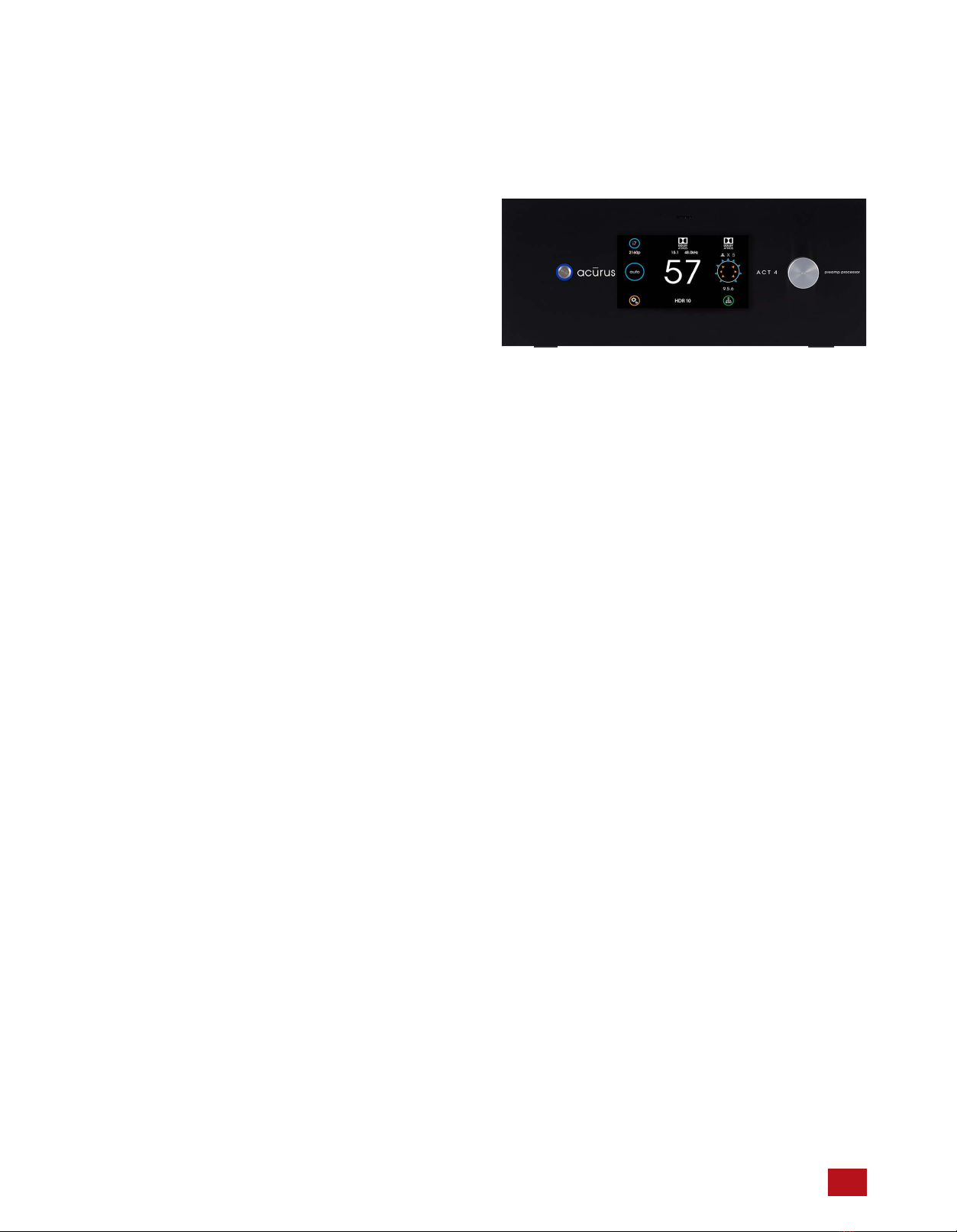
Front Panel
The front-panel of The ACT 4 was designed with beauty,
simplicity and control confidence as the primary goals.
Touch-sensitive LCD Screen: The ACT 4 features a touch-
sensitive screen for direct control and status monitoring on
the unit. The full-color, high-contrast TFT screen features
familiar mobile-device-like icons.
Power on/Standby button: The left side of the front panel
features a momentary-contact, machined-aluminum power
button for switching the unit from standby to power on mode.
The light ring surrounding the power button illuminates red in
standby mode and blue in normal operation.
Volume/Mute knob: The right side of the ACT 4 front panel
features a large machined-aluminum volume knob with
detents. This knob also mutes the processor outputs when
pressed. The volume number changes from white to red
during muted state.
IR Sensor window: A multi-function infra-red (IR) and
ambient light sensor window is located in the center of the
front panel, directly above the touch screen. This
sophisticated sensor receives IR commands and senses
changes in ambient lighting for automatically controlling LCD
backlight brightness.
Side Panels
The left and right side panels of the Acurus ACT 4 include
ventilation slots to help regulate the internal temperature of
the unit even when rack-mounted.
Acurus ACT 4 Immersive Processor USER GUIDE Revision 20230518
Document 1000905
Volume/Mute Knob
Touch-sensitive LCD Screen
Power on/Standby Button
IR Sensor Window
6
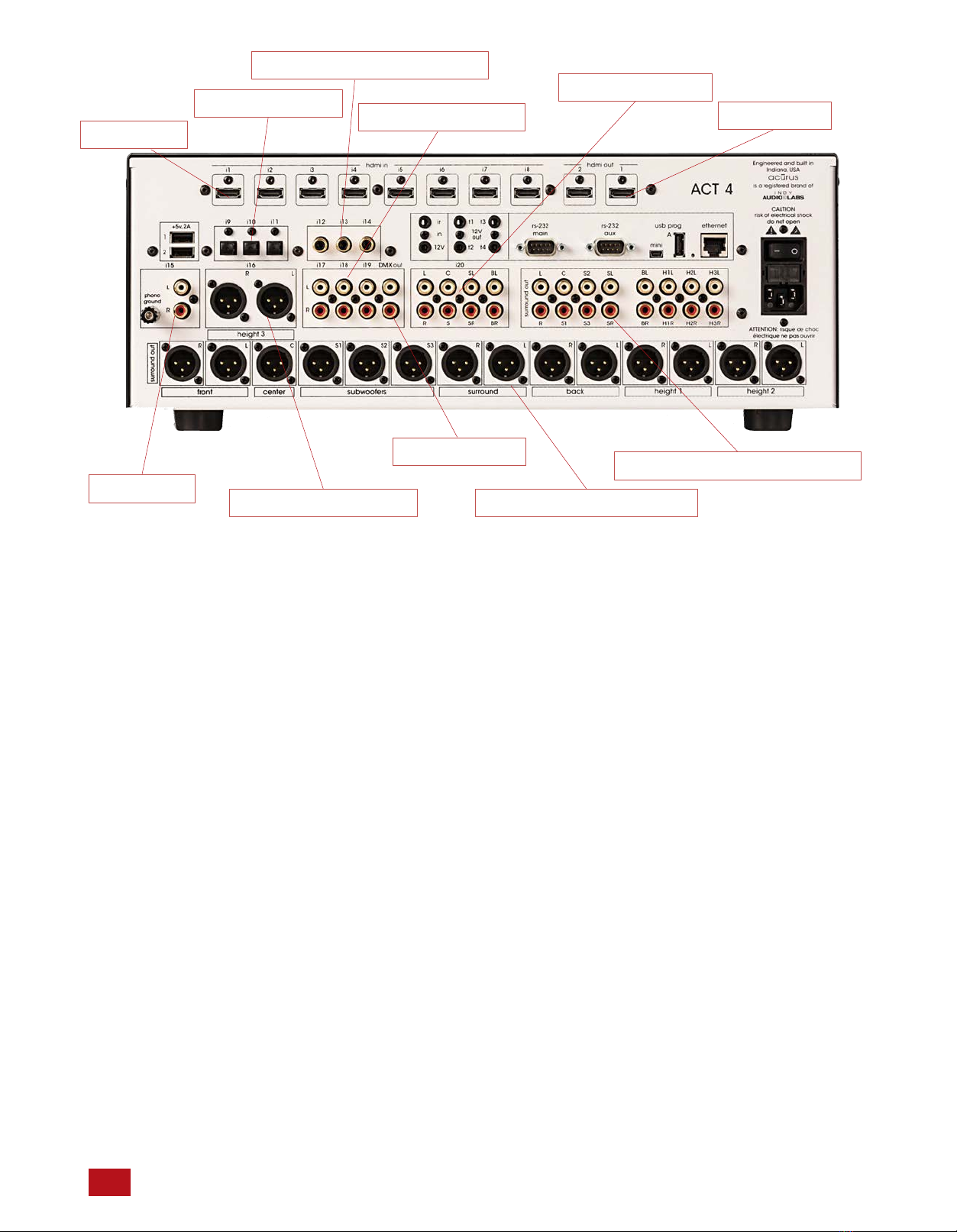
Rear Panel
The rear panel of the Acurus ACT 4 is designed for ease of
connection and expandability. A white powder coat finish
makes connector labels easy to see in dimly lit rack mounting
situations.
HDMI Inputs (i1 – i7*): At the top back left of the unit are
seven sets of HDMI 2.0 inputs for connecting modern source
devices such as Blue-Ray players, Set Top Boxes,
Streaming media adaptors and any other HDMI-compliant
devices. All inputs are compliant with HDCP 2.2
requirements for copy-protected 4K media. *NOTE: some
variations of the HDMI board may have 4 or 8 inputs.
HDMI Outputs (1 – 2): At the top back right of the unit are
two sets of HDMI 2.0 outputs for connecting up to two HDMI
sink devices such as Flat Panel TVs, Projectors or HDMI
switchers. Both HDMI outputs carry the same source signal.
Output 2 is compliant with the newly released HDCP 2.2
requirements for copy-protected 4K media. Output 1 is
HDMI version 1.4 and should only be used as an
independent monitor output for troubleshooting.
Phono Input (i15): In the rea left of the unit is a phono input
with ground lug. The phono input (i15) is capable of
supporting both Moving Magnet and high-output Moving Coil
cartridges.
Optical Audio Inputs (i9 – i11): The ACT 4 includes three
optical digital audio inputs for connecting TOSLink audio
sources such as TVs, Gaming systems, CD players or
streaming media sources from companies such as Amazon,
Google or Roku. These inputs are designed to handle hi-res
audio sources (up to 192kHz/24bit).
Coax Digital Audio Inputs (i12 – i14): The ACT 4 includes
three coax digital audio inputs for connecting SPDIF audio
sources such as TVs, gaming systems, CD players or other
streaming media sources. These inputs handle multichannel
and hi-res audio sources (up to 192kHz/24bit).
Balanced XLR Output/Input (i16): To the right of the phono
input is a pair of balanced XLR male connectors (i16). These
connectors can be configured as height 3 outputs (default) or
as inputs (i16) using a pair of female-female gender changer
adaptors and the i16 input mode setting in the level settings
menu. Configured as an input, this connection is ideal for
connecting balanced sources such as high-end CD players,
external 2-channel pre-amplifiers or other professional audio
gear.
Unbalanced (RCA) analog inputs (i17 – i19): To the right of
the balanced inputs are four pairs of unbalanced (RCA)
inputs (i17 – i19). These inputs accept any line-level stereo
analog source audio inputs such as optical disc players,
streaming players or computer sound cards.
7Acurus ACT 4 Immersive Processor USER GUIDE Revision 20230518
Document 1000905
XLR (balanced) outputs (14x)Assignable output/input
Phono input
Optical inputs (3x)
Coax (digital) audio inputs (3x)
2-channel inputs (3x)
Downmix output
HDMI inputs
Multi-channel input
RCA (unbalanced) outputs (16x)
HDMI outputs

Rear Panel
The rear panel of the Acurus ACT 4 is designed for ease of
connection and expandability. A white powder coat finish
makes connector labels easy to see in dimly lit rack mounting
situations.
USB Power Outlets A, B: Two 5Vdc, .5A USB power outlets
are placed in the left rear panel to provide a convenient
method to power streaming media sources connected to the
ACT from companies such as Amazon, Google or Roku.
IR (Infra-red) and 12V Trigger Inputs: To the right of the
digital audio inputs are dual 1/8” jacks for accepting an
external Ir receiver (top) and a trigger input cable from an
external trigger out source (bottom). Pinout for the 12V
trigger input is shown below the photo:
12V Trigger Outputs (t1 – t4): To the right of the Ir and
Trigger INPUTS are four independent 12V trigger OUTPUTS.
These trigger outputs are enabled by default to go active
(high) along with ACT 4 power on. The delay times on these
trigger outputs can be individually adjusted to power on
external devices such as power amplifiers in a sequence
rather than all at once. Pinout is same as above for the
trigger input.
RS-232, USB and Ethernet Ports: One RS-232 port (main)
and an Ethernet Port are provided to enable control of the
ACT 4 from a computer or 3rd party automation control
system. The Ethernet port also provides the main networking
connection and allows for Web control via the built-in web
server in the ACT 4. A small window to the lower left of the
Ethernet port illuminates green when an active network
connection is established. Both a mini-USB jack and a large
(“A”-type) USB jack are included for downloading firmware
upgrades via a computer or a USB memory stick,
respectively.
RS-232 AUX Port (20-channel ACT 4 only): This port is a
balanced analog audio output with four fully matrixed outputs
of any output signal channel. A DB-9 to XLR breakout cable
is available from Acurus (order part number CAB-20).
12V trigger 3.5mm stereo plug pinout diagram:
Sleeve (1) = Ground
Ring (2) = Ground
Tip (3) = Trigger Voltage
Acurus ACT 4 Immersive Processor USER GUIDE Revision 20230518
Document 1000905
Mini-USB to PC firmware update port
RS-232 Control Port (Main)
IR Sensor Input
12V trigger outputs (4x)
Balanced AUX Audio out
USB Power (2x)
USB programming port
Ethernet control port
12V trigger input
8

9Acurus ACT 4 Immersive Processor USER GUIDE Revision 20230518
Document 1000905
Master Power Switch: To the back right of the ACT 4 is a
combined master power on/off switch, main AC in fuse
drawer, and AC mains inlet. The master power switch in
the off position puts the ACT 4 in a state of zero current
draw, however, in most installations, this power switch will
remain in the on position and the power on/standby control
on the front panel or through network control should be
used. The master power switch can be used to perform a
system restart. Note that settings are maintained in non-
volatile memory even with the master power switch off.
Note also that a system restart can be performed through
the settings menu without using the Master Power Switch.
Mains fuse drawer: Below the master power switch is the
mains fuse drawer. Press the tabs on the sides of the
drawer to open it and access the fuse(s) inside.
IMPORTANT NOTE: Replace the mains fuse with the
exact fuse rating called out on the product label
located on the bottom of the ACT 4 housing.
Main AC cord inlet: Below the fuse drawer is the main AC
cord inlet. Ensure the AC cord is inserted securely in this
socket.
IMPORTANT NOTE: Use only the AC cord included
with the ACT 4 and do not tamper with or alter the
ground plug.
Fuse drawer
Master Power Switch
Power cord connection
installation advice
The ACT 4 was designed for both rack-mount and shelf-
mount applications. The ACT 4 includes feet for shelf
placement. These feet are removable in order to attach
ears for rack mounting. This section provides instructions
for proper installation and setup.
General Guidelines
When planning an ACT 4 installation, keep the following
guidelines in mind:
It is ALWAYS advisable to:
1. Provide ample air space to the sides and rear of the
unit (1-2 inches is the minimum preferred). It is not
necessary to provide additional space above or below
the unit.
2. Avoid obstructing air flow through the side-facing
ventilation slits on the left and right sides of the ACT 4
unit.
3. Locate the unit near an AC power outlet or power
conditioner and avoid using extension cords or power
strips.
4. Locate the preamp processor as close as possible to
audio source units such as optical disc players, set
top boxes or music servers.
5. Whenever possible, plug audio source units into the
same power outlet or power conditioner as the ACT 4.
6. Use as short length wire leads as practical, especially
on the preamp processor inputs.
It is NEVER advisable to:
1. Enclose the unit in a rack or cabinet without air flow or
adequate ventilation, particularly across the air vents
along each side of the unit.
2. Place the unit near a source of moisture such as a
window or a live plant.
3. Place the preamp processor on a carpeted surface.
4. Remove the safety ground connector from the AC
mains cord.
Shelf Mounting
The ACT 4 preamp processor can simply rest on a flat
surface using the 4 rubber feet and mounting screws
supplied with the unit.
Equipment Rack Mounting
The ACT 4 preamp processor can easily be configured for
rack mounting by removing the 4 rubber feet and using an
Acurus (part number ARM-4) rack mount kit available from
your authorized Acurus dealer.
10Acurus ACT 4 Immersive Processor USER GUIDE Revision 20230518
Document 1000905

system connections
The ACT 4 preamp processor is designed for simple,
reliable connections in a variety of system configurations.
Following the guidelines below will ensure optimal
performance from your ACT 4 preamp processor.
IMPORTANT NOTE: Make system connections
with AC power off.
HDMI Audio/Video Source Inputs
You may connect up to seven HDMI source devices to the
ACT 4 HDMI inputs i1 – i7. All HDMI inputs support 4K HDR
and HDCP2.2 provided that high quality HDMI cables are
used. Avoid using excessively long cables (longer than 3
meters), coiling or bunching up of cables.
HDMI Display Output
Connect the video display (TV or projector) to output 2
which is the full HDMI 2.0b output. Use of output 1 should
generally be avoided as the video system is limited to HDMI
1.4 on this output. Be sure to use high-speed HDMI cabling
to avoid dropouts and loss of audio or video. For runs longer
than around 3 meters, use of DPL-certified active optical
HDMI cable is highly recommended.
Coax Digital Audio Source Inputs
Use high quality RCA interconnects to connect up to three
coax digital audio source devices to ACT 4 inputs i12 – I14.
Avoid coiling or bunching up of cables. Be sure RCA cables
are fully inserted into ACT 4 input jacks in order to avoid
dropouts or other digital signal integrity problems.
Optical Digital Audio Source Inputs
Use high quality Toslink optical interconnects to connect up
to three optical digital audio source devices to ACT 4 inputs
i9 – i11. To prevent signal integrity problems or permanent
damage to optical cables, avoid tight turns or bundling.
Phono Audio Source Input
Use a high-quality RCA interconnects to connect a turntable
to the ACT 4 phono input i15. A ground lug is included for
cartridge hum reduction.
Stereo (RCA) Audio Source Inputs
Use high quality RCA interconnects to connect up to four
analog audio source devices to ACT 4 stereo audio inputs
i17 - i20. Avoid coiling or bunching up of cables. Be sure
RCA cables are fully inserted into ACT 4 input jacks in order
to avoid hum and other analog signal integrity problems.
Stereo (XLR) Audio Source Input (optional)
Use high quality XLR interconnects along with a pair of
female-female gender changer adapters to connect a
balanced XLR stereo analog audio source device to ACT 4
stereo audio input i16. Ensure that i16 input mode is set to
“on” in the ACT 4 level settings menu.
Multichannel (RCA) Audio Source Input
The ACT 4 enables use of an external multi-channel audio
component with built-in surround decoding such as a Blu-ray
player with built-in DACs. Use four pairs of high-quality RCA
interconnects to connect such an external source device (up
to 7.1 output) to the ACT 4 multichannel input i20.
Balanced or Unbalanced Audio Pre-amp Outputs
Use high quality RCA and/or XLR interconnects to connect
to external power amplifiers, subwoofers and/or powered
loudspeakers. XLR and RCA outputs are driven
independently and so both sets of outputs can be used
simultaneously.
Trigger In and Out Control
To enable automatic power on/standby control of the ACT 4
from an external control system or power conditioner,
connect a trigger cable from the trigger out of the controlling
device to the 3.5mm 12V trigger input on the ACT 4. The
ACT 4 trigger input jack is wired with its tip active and will
accept either a stereo or mono plug.
Similarly, to enable the ACT 4 to automatically control
external power amplifiers and/or send a power signal to an
external control system, connect one of the four trigger
outputs t1 – t4 to the device to be controlled via a trigger
cable for each slave device.
USB Power
Connect up to two USB-powered streaming media devices
or active HDMI cables to this pair of 5V USB power outputs.
Control Networks
Ethernet: In order to take advantage of Acurus Enhanced
Ethernet Control (E2C), connect the Ethernet port to a
10/100 or faster home network router or switch port via a
standard CAT 5e or newer Ethernet cable. The network
activity indicators near the Ethernet jack illuminates green
when the ACT 4 is powered on and an active network
connection is detected.
This port may also be directly connected to a system
controller utilizing Ethernet command protocols (see section
“Ethernet Command Protocol”.
RS-232: Connect the RS-232 port labelled “main” to a
system controller or computer using a 9-pin RS-232 serial
cable for full bi-directional control and monitoring of the unit.
Mains (AC) Power
The ACT 4 is equipped with a high-quality 14 gauge, 3-
conductor power cord. Plug this cord into the back of the
pre-amp processor and then into a nearby AC outlet. Avoid
using any extension cords or plugging into other
components with rear-panel switched outlets.
11 Acurus ACT 4 Immersive Processor USER GUIDE Revision 20230518
Document 1000905
Acurus ACT 4 Immersive Processor USER GUIDE Revision 20230518
Document 1000905
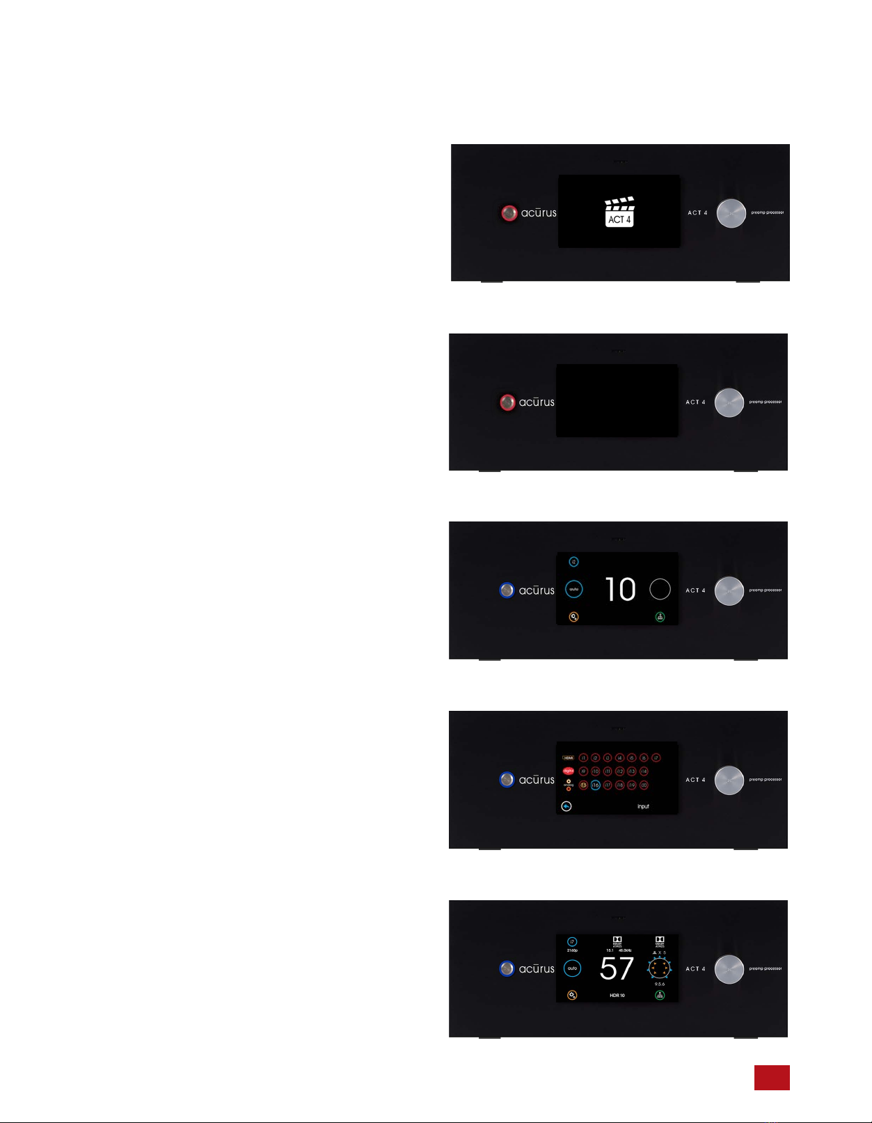
basic operation
This section describes basic operation of the ACT 4 out-of-
the-box using the front panel features.
AC Power on and bootup
Ensure the ACT 4 rear panel power switch is set to on. With
AC power applied, the ACT 4 boots up and initializes. Allow
2 minutes for initial bootup from full power off. Once the ACT
4 boots up, standby mode can be used to turn the unit on
and off instead of booting up from a full power down.
Standby Mode
At the end of the bootup process, the ACT 4 power light
blinks and the LCD screen goes dark indicating that bootup
is complete and the unit is ready to operate.
Power On
Press the power button on the left side of the front panel.
The button illuminates blue and the LCD screen illuminates.
With no input signal present, the Loudspeaker Format
Indicator appears as a blank circle.
Select Input
Select the input to be played on the upper left of the touch
screen.
Adjust Volume
Adjust volume using the volume knob on the right side of the
front panel. With an active input stream, the LCD display will
show the incoming signal format and the active speakers
playing.
12
13 Acurus ACT 4 Immersive Processor USER GUIDE Revision 20230518
Document 1000905
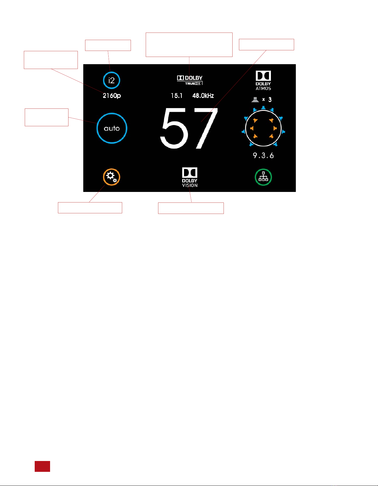
Input Selector Volume Indicator
Incoming Signal
Format, Channel Count
and Sample Rate Indicators
Video Resolution
Indicator
Sound Mode
Selector
main user interface
Main
The main screen of the ACT 4 provides complete system
status and incoming stream information in one clear, concise
view.
Input Selector: Touch this button to select an input to the ACT
4. (see page 17)
Video Resolution Indicator: This shows the video resolution
incoming on the selected HDMI input if inputs i1-i7 are selected
and a video signal is present. Resolutions from 480i through
2160p are supported.
Sound Mode Selector: This shows the currently selected sound
processing mode. Touch to change the mode. (see page 18)
Settings Page Button: Touch the settings button at the lower
left of the front panel display to access and adjust ACT 4
settings and preferences. Speaker layout and settings, Dolby,
DTS and other global system preferences are setup here. (see
page 21)
Incoming Signal Format Indicator: The ACT 4 main screen
shows input signal information above the volume number. The
color graphics make encoding and decoding technologies very
clear and easy-to-read.
Incoming Channel Count and Sample Rate: The ACT 4 shows
the incoming signal channel count (from 1.0 to 15.1) and
decoded sample rate (from 32kHz to 192kHz) on the main
page in the top middle (above the volume number).
Volume Indicator: A scale 1-99 volume indicator displays
present system volume. When muted, the volume indicator
switches from white to red in color.
HDR Format Indicator: : This shows the HDR video type
incoming on the selected HDMI input if inputs i1-i7 are selected
and an HDR video signal is present. Types including HDR10,
HLG and Dolby Vision are supported.
HDR Format Indicator
Settings Page Button

Acurus ACT 4 Immersive Processor USER GUIDE Revision 20230518
Document 1000905
Loudspeaker
Format
Indicator
Main (continued)
Output Processing Indicator: This indicator shows the
processing applied (if any) to the input signal. Processing
technologies (also referred to as “post-processing”) can include
“direct” as well as various other up-mixing technologies from
Dolby and DTS. Both Sound Mode and Loudspeaker layout
impact the output processing applied.
Loudspeaker Format Indicator: To the far right in the main
screen is the signal format indicator. A quick glance shows the
active (sound-producing) loudspeakers in the room resulting
from a combination of the input signal format, the sound mode,
the loudspeaker layout and any additional output processing
being applied. The number below the diagram indicates the
numeric description of the resulting processed signal format.
Note that this format is often not the same as the input signal
format, particularly if up-mixing or down-mixing is being
performed.
Network Indicator/Settings Button (lower right): This button
serves to bring up the Network Quick-connect screen for
quickly retrieving the IP address of the ACT 4. It also indicates
network status by illuminating bright green with an active
Ethernet connection and dimmed out with no connection
detected. (see page 17)
Network Indicator
Output
Processing
Indicator
14

15 Acurus ACT 4 Immersive Processor USER GUIDE Revision 20230518
Document 1000905
HDMI Inputs i1 –i7
Optical inputs
i9 -i11
Analog Inputs i16 –i19
Input Selection
Touching the input button brings up the input selection page.
Here you can select from HDMI sources, digital audio sources
and analog input sources.
Coax digital
inputs i12 -i14
Multi-channel Analog
Input i120
Phono Input
i15
Network Quick-Connect
Touching the green network button on input lower right of the
main page brings up the current IP address of the ACT 4. This
address can be used for remote control and setup. (see page
38)
ACT 4 IP address

Acurus ACT 4 Immersive Processor USER GUIDE Revision 20230518
Document 1000905
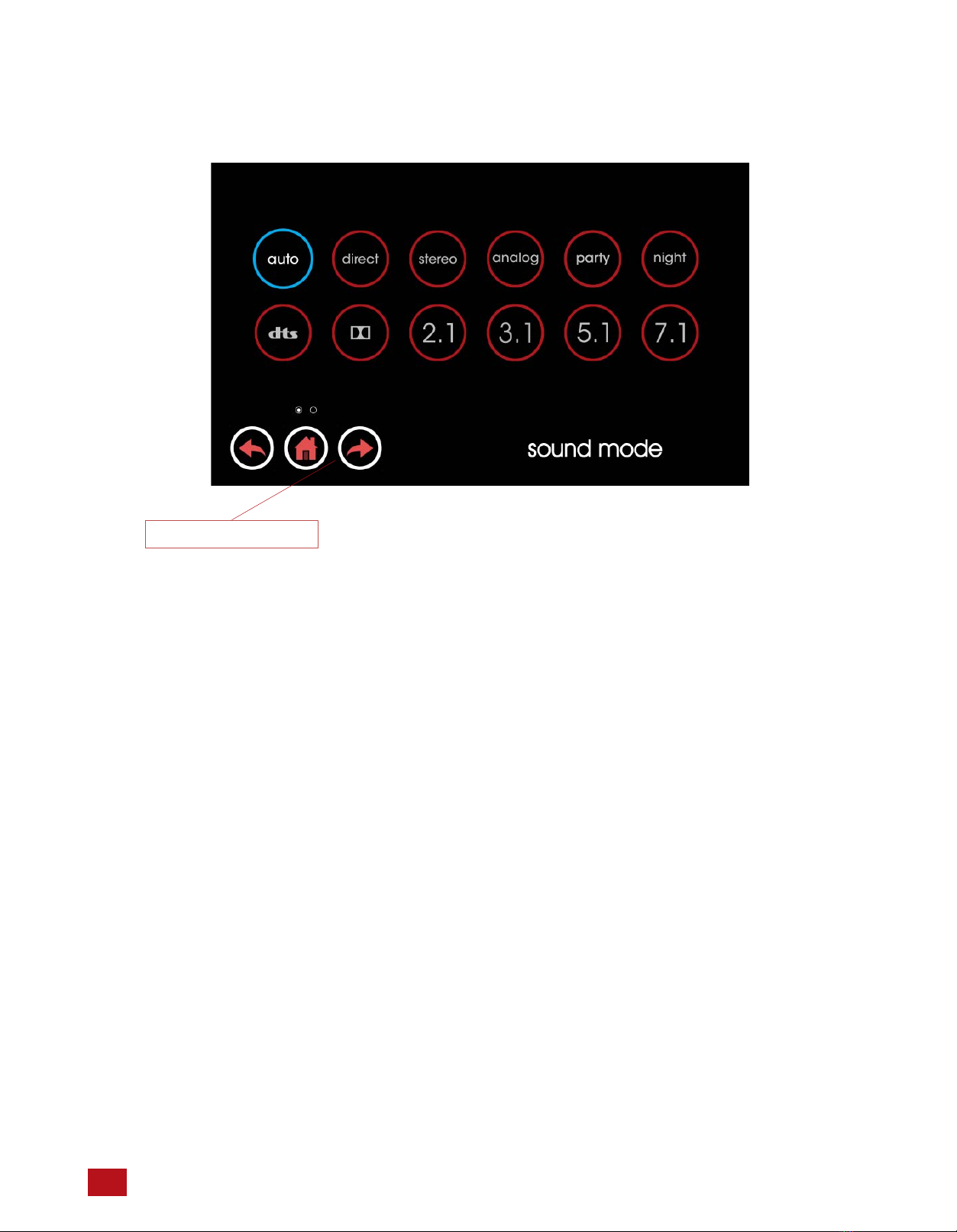
Sound Mode
Touching the Sound Mode Selector brings up the input
selection page. Here you can control how the ACT 4 processes
the source signal.
Auto: This is the default processing mode. In auto mode, the
ACT 4 automatically decodes, up-mixes or down-mixes the
source signal* according to the source signal type and the
current loudspeaker layout. The result is that native Dolby and
DTS signals are decoded natively and all loudspeakers in the
room are utilized regardless of input signal format changes.
Two-channel analog sources are up-mixed according to the
room layout. Multi-channel and/or object-based digital signals
from HDMI or other digital inputs are up-mixed or down-mixed
according to the loudspeaker layout.
* Note that auto mode is not available for multichannel analog
input i20 as this input is a direct analog pass-through input.
Direct: This processing mode is available for any input signal
source. For most loudspeaker layouts equal to or larger than
5.1, direct mode reproduces audio or video content utilizing the
same speaker layout as the source signal was originally
recorded in. Analog signals are passed through from any 2-
channel or multi-channel input (i21) without any subsequent
processing. Digital multi-channel signals (such as 5.1 or 7.1)
are passed through to the appropriate loudspeakers according
to the source format. Note that loudspeakers not used in the
source signal format (for example, overhead loudspeakers in a
7.1 movie) will not playback. Note also that missing
loudspeaker signals due to room layout limitations (for
example, rear surround speakers in a 7.1 movie being played
in a 5.1 speaker layout) will not playback.
Stereo: This mode is available for any input signal source.
Stereo allows the ACT 4 to play audio or video media in a
basic left-right (2-channel stereo) format. Multi-channel audio is
automatically down-mixed to 2-channels. Any other
loudspeakers present in the room other than the main left and
right speakers are not driven.
analog: This mode is available for any analog stereo (2-
channel) or multi-channel input (i16 - i20). Analog mode
bypasses any digital processing for utilizing the ACT 4 as a
pure 2-channel pre-amplifier. This mode is ideal for 2-channel
or multi-channel critical listening with large, high-performance
loudspeakers.
party: This mode is available for all inputs except i20. Party is a
variation of auto mode in which any signal is up-mixed or
down-mixed to 2.1 channels. The resulting left and right
loudspeaker signals are then routed to all available left and
right loudspeakers including surrounds and overhead
speakers. This mode is ideal for providing party music to fill a
room with sound.
night: This mode available for all inputs except i20. Night is a
variation of auto mode in which dynamic compression is
applied to the signal to reduce its loudness. In addition, the
subwoofer signal is automatically attenuated. The result is an
overall quieter signal for listening at night without disturbing
other members of the household.
16
17 Acurus ACT 4 Immersive Processor USER GUIDE Revision 20230518
Document 1000905
Sound Mode (continued)
DTS: This sound mode is available for any inputs except i20.
DTS mode automatically utilizes the best native DTS decoding
method for any incoming DTS signal and utilizes DTS Neural:X
surround up-mixing to fill all available loudspeakers in the
room, including overhead speakers, if present. PCM signals
are also up-mixed with Neural:X if selected in Sound Mode
Preferences (see settings page).
Dolby: This mode is available for any inputs except i20. Dolby
mode automatically utilizes the best native Dolby decoding
method for any incoming Dolby signal and utilizes Dolby
Surround up-mixing to fill all available loudspeakers in the
room, including overhead speakers, if present. PCM signals
are upmixed using Dolby Surround Up-mixer by default unless
changed in Sound Mode Preferences (see settings page).
stereo: This mode is available for all inputs except i20. Stereo
mode automatically limits playback to the main left and right
loudspeakers in the room. This mode automatically down-
mixes multi-channel signals to 2 loudspeakers whenever
necessary. LFE signals (where present) are mixed to the left
and right loudspeakers in the case where left and right
loudspeakers are set to “large” (see loudspeaker settings).
2.1: This mode is available for all inputs except i20. 2.1 mode
is the same as stereo mode but with the addition of the
subwoofer channel for rendering LFE. If the main left and right
loudspeakers are set to small, the subwoofer channel also
contains down-mixed low-frequency audio from the other
source channels. 2.1 mode can be useful for stereo source
media playback or for playing back TV audio without surround
channels.
5.1: This mode is available for 5.1 or greater channel count
input signals. 5.1 mode automatically limits playback to five
main audio bed loudspeakers in the room plus the subwoofer.
This mode automatically down-mixes multi-channel signals
greater than 5.1 to 5.1 loudspeaker format whenever
necessary. 5.1 mode can be useful for providing a baseline
when evaluating legacy 5.1 source media with auto (up-mixed)
mode.
7.1: This mode is available for 7.1 or greater channel count
input signals. 7.1 mode automatically limits playback to seven
main audio bed loudspeakers in the room plus the subwoofer.
This mode automatically down-mixes multi-channel signals
greater than 7.1 to 7.1 loudspeaker format whenever
necessary. 7.1 mode can be useful for providing a baseline
when evaluating legacy 7.1 source media with auto (up-mixed)
mode. 7.1 mode can also prove useful as a baseline for
evaluating the effects of overhead sound objects in immersive
surround material encoded in formats such as Dolby Atmos
and DTS:X.
Forward Arrow to “On the Fly” Screen: Touch the forward
arrow to change parameters on the fly for DTS dialog control
and Bass and Treble (see page 20)
To “On the Fly” Screen

“On-the-Fly”
Pressing the left or right arrow in the sound mode control
screen brings up the on-the-fly adjustments page. Here,
some of the most impactful parameters affecting audio can
be adjusted.
DTS Dialog Control: The latest generation of object-based
DTS decoding allows you to directly boost dialog audio in
new DTS-exclusive media content that includes this feature
in the mix. Dialog adjustments can be useful in noisy or
reverberant environments in order to help make dialog more
intelligible. People with impaired hearing may also benefit.
Note that the content creator may disable the use of this
feature in the mix and so Dialog Control may not always be
available on every title. Note that this is not the same as the
center loudspeaker level as this is an audio object level
control rather than a channel level control.
Bass and Treble Levels: The bass and treble levels on the
overall audio signal can be adjusted +/- 12dB in steps of
1dB using these adjustments. This feature is designed to
compensate for variances in program material and listening
preference rather than for room or loudspeaker fine-tuning.
For the latter, adjustment of the loudspeaker PEQ settings is
recommended.
18Acurus ACT 4 Immersive Processor USER GUIDE Revision 20230518
Document 1000905

19 Acurus ACT 4 Immersive Processor USER GUIDE Revision 20230518
Document 1000905
dts settings
Loudspeaker
Settings
Screen Preferences
settings overview
Settings Page
Touching the settings button brings up the settings page.
Internal Temperature Monitor: Displays the internal
temperature of the ACT 4 to ensure optimal operating
conditions. Recommended range is 25 to 45 degrees C.
Loudspeaker Settings: Opens the setup pages for loudspeaker
layout selection, EQ, delay and crossover.
Sound Mode Preferences: Preferences for Night mode and
PCM signal input handling.
HDMI Settings: Adjustments for lip sync delay and input/output
HDMI compatibility.
Dolby Settings: Settings include Dolby compression and center
spread.
DTS Settings: Settings include DTS compression.
Level Settings: Settings for max volume, A/D sample rate and
input 16 mode.
Trigger Setup: Settings for delay on trigger outputs and IR
internal/external toggle
Screen Preferences: Settings related to screen brightness and
sleep timeout.
Firmware Update: Displays firmware version and restarts the
ACT 4 in order to enter reprogramming mode.
Network Settings: Settings to enable DHCP or Static IP setup
for network connectivity and control.
Factory Reset and System Restart: Restarts the ACT 4 with
setup parameters preserved (restart) or all settings including
setup parameters reset (factory reset).
Level settings
Factory Reset and
System Restart
Trigger Setup
Internal Temperature
Monitor
Firmware Update Network Settings
Dolby settings
HDMI settings
Sound Mode
Preferences
Other INDY AUDIO LABS Amplifier manuals


