Inelco Grinders Truncator User manual


IMPORTANT SAFETY INSTRUCTION
On installation and operation of this machine, the safety instructions stipulated in this USER MANUAL must
be read and complied with.
This MANUAL must always be easily accessible to those who are responsible for the installation, operation
and maintenance of the machine. DISPOSAL
Do not dispose of metal equipment with ordinary waste. Itis collected and divided by material
type so that it can be recycled in an environmentally sound manner.
DK

INELCO GRINDERS A/S TRUNCATOR
Inelco Grinders A/S, Industrivej 3, DK-9690 Fjerritslev, Denmark 3
Contents
General description of the machine...................................................................................... 3
What is included................................................................................................................... 4
Installation............................................................................................................................ 5
Configuring the truncator...................................................................................................... 7
Adjustment of grinding tracks on the diamond disc .............................................................. 9
Use of the truncator ........................................................................................................... 10
Replacing the grinding disc for truncating........................................................................... 11
Maintenance...................................................................................................................... 11
Important safety information
The truncator may ONLY be used following correct installation on an Ultima-TIG or Ultima-TIG-CUT
grinder.
General description of the machine
This Truncator module has been developed and designed for the truncation of ground tungsten electrodes
used in TIG welding. It may only be used if it is correctly installed on an Ultima-TIG or Ultima-TIG-CUT
grinder as described in this manual.
The module can be used both with and without AutoGrind fitted and with the electrode holder from the
above grinders or the electrode holder from the AutoGrind module.
Provided the truncator module is installed correctly, no changes are required with respect to the original CE
marking or the use of the grinder with respect to safety. The module does not require a separate CE
marking and neither does it need a separate EU Declaration of Conformity.

INELCO GRINDERS A/S TRUNCATOR
Inelco Grinders A/S, Industrivej 3, DK-9690 Fjerritslev, Denmark 4
What is included
Pos
Part no.
Qty.
Description
1
44490517
1
Grinding disc for truncating
2
44520009
1
Packing ring for inspection cover
3
41530540
1
Washer Ø5x30 mm
4
44496525
1
Screw 5x25mm left-hand stainless
5
44490910
1
Frame for truncator
6
40320410
4
Retaining screw M4x10 PH Torx A2
7
44470224
1
O-ring Ø24x2 mm
8
44523010
1
Eccentric guide
9
44523005
1
Lock for eccentric guide
10
44520048
1
Locknut
11
Tightening screw - see page 5 for part numbers
12
44510290
1
Inspection cover NX
13
44523015
1
Housing for stick-out adjustment
14
44523020
1
Bolt for stick-out
15
40110406
2
Screw M4x6 mm

INELCO GRINDERS A/S TRUNCATOR
Inelco Grinders A/S, Industrivej 3, DK-9690 Fjerritslev, Denmark 5
Positions nr. 11
Installation
Preparation of installation
On reception of the Truncator, part nos. 7, 8, 9, 10, and 11 are found separately in the box. Prior to using
the product, these parts must be installed on the Truncator frame (5):
1. Insert part no. 7 (O-ring) into the hole on the front plate such that it is flush against the flange, fig. 1
2. Insert part no. 8 (eccentric guide) into the hole on the front plate (5) and screw into position with part
no. 9 (lock for eccentric guide), fig. 2
3. Then screw part no. 10 (locknut) and part no. 11 (tightening screw) onto the thread of part no. 9, fig. 2
( Fig 1 ) ( Fig 2 )
Pos.
Part no.
Description
A
44520004
Tightening screw
B
44470124
Rubber pack Ø25mm
C
44520027
Bronze bearing Outward
D
40310404
Pointed screw M4x6mm

INELCO GRINDERS A/S TRUNCATOR
Inelco Grinders A/S, Industrivej 3, DK-9690 Fjerritslev, Denmark 6
Prior to installation of the Truncator on the Ultima-TIG grinder, the latter must be disconnected from the
electrical network and the grinding chamber must be emptied of grinding fluid.
Remove the frame and inspection cover on the grinder. Set these aside in case the grinder is later used
without the Truncator. See the manual for the grinder.
On older Ultima-TIG grinders (serial nos. below 2037-…) two new holes must be drilled to enable the
Truncator to be fitted. See enclosed instructions. A set with drill bits and a threaded tap can be ordered by
quoting part no. 75523030. Alternatively, a new grinding chamber with four holes (part no. 49520000) or a
complete grinding chamber kit with four holes and a new angle setting (part no. 75523020) can be ordered.
If the Ultima-TIG grinder is not new and has been in use, the grinder housing must be cleaned internally
and the grinding disc checked for wear. If it is worn, it must be replaced (part no. 44490512).
Clean the groove for the packing ring on the front of the grinding chamber in order to ensure that there will
be no leaks.
Remove the left-hand screw and brass U washer that keep the
grinding disc in place and set them aside in case the
Truncator needs to be removed again.
Fit the grinding disc for truncating (1) with the accompanying
washer (3) and left-hand screw (4).
Fit the packing ring (2) into the groove on the grinder frame.
Mount the Truncator module onto the grinder frame by means
of the four screws (6).
Install the accompanying stick-out adjuster on the stainless
steel table next to the Ultima-TIG grinder.
INELCO GRINDERS A/S TRUNCATOR
Inelco Grinders A/S, Industrivej 3, DK-9690 Fjerritslev, Denmark 7
The grinding liquid is filled up to the mark on the
spectacle and is now ready to be set.
The included cut-out adjustment is mounted on the
stainless-steel table next to the Ultima-TIG grinder.
Configuring the truncator
Adjustment of stick-out after grinding
After grinding of the electrode on Ultima-TIG, the stick-out of the electrode must be adjusted:
1. Grind an electrode on the Ultima-TIG grinder.
2. Loosen the electrode in the stick-out adjuster on the grinder after grinding.
3. Pull the electrode a little way out of the electrode holder such that at least 20 mm is sticking out of
the clamp.
4. Insert the electrode into the stick-out adjuster for the truncator and secure it in the electrode holder
by rotating the electrode holder clockwise.
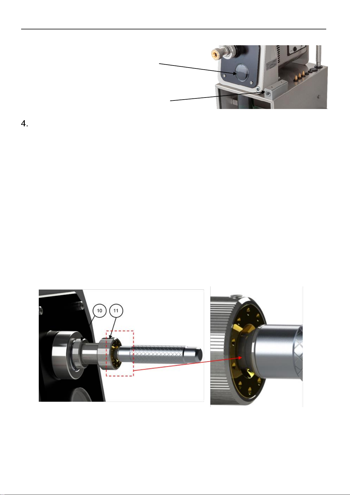
Adjustment of the truncated diameter
In order to set the desired truncated diameter, the following steps must be followed:
1. Reset the position by screwing the locknut (10) and tightening screw (11) all the way in.
2. Insert the electrode holder into the truncator so that the tip of the electrode touches the grinding
disc. Insert it carefully, as the tip can easily be damaged and the length thus altered.
Note the gap between the electrode holder and the tightening screw (11), marked with a red arrow.

INELCO GRINDERS A/S TRUNCATOR
Inelco Grinders A/S, Industrivej 3, DK-9690 Fjerritslev, Denmark 8
3. Screw out the tightening screw (11) until it touches the electrode holder, which is pushed all the way
in to the grinding disc.
4. Then screw the tightening screw (11) a number of revolutions (each revolution corresponds to 1 mm
in the length of the tip) and lock it with the locknut (10).
5. Pull the electrode holder a little way out so that the electrode does not touch the grinding disc.
6. Start the machine. The tip of the electrode is now truncated by pushing the electrode holder against
the grinding disc and rotating it at least 360°.
7. Turn off the machine, take out the electrode holder and measure the truncated diameter with the
electrode seated in the electrode holder.
8. If the desired diameter has not been achieved, set the position of part nos. 10 and 11 again.
Larger diameter. Screw part nos. 10 and 11 inwards (clockwise) in order to bring the tip of the
electrode closer to the grinding disc, thereby increasing the truncated diameter.
Repeat grinding to truncate the electrode with the new setting.
Smaller diameter. Screw part nos. 10 and 11 outwards (anticlockwise) in order to bring the tip of
the electrode further from the grinding disc, thereby decreasing the truncated diameter. Grind the
electrode to a point once more and begin grinding to truncate the electrode again.
Continue the above until the desired truncated diameter has been achieved and the Truncator is
thereby configured.

INELCO GRINDERS A/S TRUNCATOR
Inelco Grinders A/S, Industrivej 3, DK-9690 Fjerritslev, Denmark 9
Adjustment of grinding tracks on the diamond disc
On the grinding disc for truncating, the diamond layer covers the first 8 mm from the outer edge towards the
center.
Three standard settings, A, B and C, are specified which each cover a truncated diameter of 2 mm. This
provides several grinding tracks on the grinding disc and thus better utilization of the diamond layer.
The position on the grinding wheel is set on the eccentric guide (8).
This has a locking ring (9) to lock the position.
INELCO GRINDERS A/S TRUNCATOR
Inelco Grinders A/S, Industrivej 3, DK-9690 Fjerritslev, Denmark 10
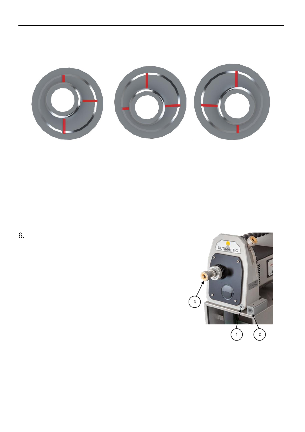
Adjustment of the position on the grinding disc takes place on the eccentric guide (8). This has a locking
ring (9) to fix its position. The 3 positions are indicated by lines on the guide (8). The lines for the position in
question must point vertically upwards. See illustrations below –seen from the front and marked with red
lines:
Position A Position B Position C
The position of the eccentric guide can be placed steplessly between the three marks, which makes is
possible to use more of the grinding disc when truncating diameters below 2 mm.
Note that the two outer positions, A and C can, as a maximum, be used for a truncated diameter of 2
mm.
If a larger truncated diameter (Ø2 mm - 4 mm) is required, the eccentric guide must be positioned midway
between positions A and B, or B and C.
Use of the Truncator
1. Grind an electrode tip on the Ultima-TIG grinder.
2. Loosen the electrode in the stick-out adjustment (1) on
the grinder.
3. Pull out the electrode approx. 20 mm. Insert it into the
stick-out adjustment for the Truncator (2) and secure it.
4. Insert the electrode holder into the truncator (3) without
letting the electrode touch the grinding disc.
5. Start the grinder and push the electrode holder with
moderate force in a rotating movement against the
grinding disc. Pull it a little away when grinding is
complete. Ensure that the electrode holder has turned
a full 360° revolution against the grinding disc.
6. Turn off the grinder and take out the electrode holder
once the grinder has come to a complete stop.
After a large number of grinding operations, the geometry of the tip can change, and it is recommended,
that random checks of the diameter of the tip be made and the Truncator reconfigured as and when
needed.

INELCO GRINDERS A/S TRUNCATOR
Inelco Grinders A/S, Industrivej 3, DK-9690 Fjerritslev, Denmark 11
Replacing the grinding disc for truncating
1. Drain the Ultima-TIG grinder of grinding fluid via the drain hose on the side.
2. Remove the 4 screws that secure the module to the grinding chamber on the Ultima-TIG, after
which the entire module can be removed and there will be access to the disc.
3. Loosen and remove the M5 bolt that retains the grinding disc. Note left-hand thread!
4. The used grinding disc can now be removed and a new grinding disc fitted.
5. Check the grinder’s grinding disc for wear and replace if necessary (Ultima-TIG grinding disc part
no. 44490512).
6. Refit the washer and left-hand bolt, before fitting the Truncator module by means of the 4 screws.
Make sure that the packing ring for the module is correctly seated in the groove on the grinding
chamber. Replace the packing ring if it is damaged.
7. Fill grinding fluid up to the mark on the inspection cover.
Maintenance
The Truncator module should typically be cleaned quarterly or after 5,000 grinding operations, in addition to
when service is carried out on the Ultima-TIG grinder or when the grinding disc for truncating needs to be
replaced.
Cleaning is carried out by dismantling the Truncator module as described in section 7, cleaning it in hot
water and drying it with a dry cloth or paper.
We recommend that the packing ring, part nos. 44520009 and 44470224, be replaced if this is damaged.

Also available for Ultima-TIG-S for truncating of larger
electrodes up to 8 mm Item No. 75523011
Table of contents
Popular Welding System manuals by other brands

Tokentools
Tokentools Metalmaster 200d Pro DC GTAW instruction manual

Parweld
Parweld XTM 201Di Operator's manual

ALKATEM
ALKATEM 8000 F Operator's manual

MK Welding
MK Welding Multi-GMAW 200 LCD PFC user manual

Lincoln Electric
Lincoln Electric SAE-400 SEVERE DUTY IM727 Operator's manual

Comparc
Comparc DELTA MIG 455 owner's manual


