INNO Instrument M9 User manual

User's Manual
Version:V0.01

01
PAGE
User’s Manual
INNO Instrument, Inc.
Preface....................................................................................................................................4
Chapter1 Technical Parameters.................................................................................................5
Applicable Fiber Type....................................................................................................................5
Splice Loss....................................................................................................................................5
Splice Mode...................................................................................................................................5
Heat Oven.....................................................................................................................................5
Power Supply.................................................................................................................................5
Size and Weight.................................................................................................................6
Environmental Conditions.........................................................................................................6
Others............................................................................................................................................6
Battery precautions...................................................................................................................6
Chapter 2 Installation.....................................................................................................................7
Safety Warning and Precautions...................................................................................................7
Safety Warnings......................................................................................................................7
Maintenance and External Care Precautions........................................................................8
Transport and Storage Precautions..........................................................................................8
Installation upon Delivery............................................................................................................8
Unpacking the Splicer................................................................................................................8
Overview of External Parts ...........................................................................................................9
Power Supply Method............................................................................................................10
Loading or unloading Battery.......................................................................................................10
Charging..............................................................................................................................11
Battery Status..............................................................................................................................11
Battery Refresh Cycle............................................................................................................12
Heat Oven..............................................................................................................................12
Chapter 3 Basic Operation..........................................................................................................13
Turn On the Splicer......................................................................................................................13
Contents

02
PAGE
User’s Manual
INNO Instrument, Inc.
Adjust Monitor Angle...............................................................................................13
Adjust LCD Backlight Brightness............................................................................14
Preparing the Fiber..........................................................................................14
How to Make a Splice.............................................................................................15
Put the optical ber in..........................................................................................15
Inspecting the Fibers..........................................................................................15
Splicing............................................................................................................16
How to Protect the Splice.......................................................................................16
Steps for Heating....................................................................................................16
Chapter 4 Splice Mode..........................................................................................18
Displaying the Current Splice Mode........................................................................18
Selecting a Splice Mode..........................................................................................19
Steps of Normal Splicing Program........................................................................20
Pre-Fusion............................................................................................................20
Fusion.....................................................................................................................20
Splicing Process.....................................................................................................20
Parameters for Normal Splicing Process.................................................................21
Chapter 5 Splice Option..........................................................................................23
Splice Mode Setting..........................................................................................23
Chapter 6 Heater Mode..........................................................................................25
Select Heat Mode....................................................................................................25
Edit Heater Mode..........................................................................................26
Delete Heat Mode..........................................................................................27
Heater Mode Parameters........................................................................27
Chapter 7 Maintenance Menu...............................................................................28
Replace Electrodes..........................................................................................28
Replacement Procedure..........................................................................................28
Stabilize Electrodes..........................................................................................29

03
PAGE
User’s Manual
INNO Instrument, Inc.
Operation Procedure..........................................................................................29
Diagnostic Test........................................................................................................29
Operation Procedure..........................................................................................29
Dust Check............................................................................................................30
Operation Procedure..........................................................................................30
Motor Calibration..........................................................................................30
Operation Procedure..........................................................................................30
Arc Calibration........................................................................................................30
Operation procedure..........................................................................................31
Electrode Setting....................................................................................................31
Update Software..........................................................................................31
Chapter 8 Other Functions & Utilities.....................................................................32
Data Storage..........................................................................................................32
Display Splice Record..........................................................................................32
Delete Splice Record..............................................................................................32
Cancel Data Storage..........................................................................................32
System Setting.......................................................................................................32
Monitor Position......................................................................................................33
Power Save Option..........................................................................................34
System Information..........................................................................................34
Appendix I............................................................................................................35
Appendix II............................................................................................................37
Appendix III............................................................................................................40

04
PAGE
User’s Manual
INNO Instrument, Inc.
Thank you for choosing M9 Arc Fusion Splicer from INNO Instrument. M9 adopts
innovative product design and exquisite manufacturing technology so as to deliver
unprecedented splicing experience to customers.
The totally new technology greatly reduces splicing , and advanced estimation
method and alignment technique ensure the accuracy of splice loss estimation.
The simple-but-trendy product design, sophisticated internal structure and reliable
durability make the splicer be suitable for any operating environment. Dynamic
operation interface and automatic splice mode provide users great convenience.
For more information of M9, please visit our ofcial website at
www.innoinstrument.com
Standard accessory:
FH-40、FH-900、
FH-200/250S
This User Manual explains the use, performance characteristics, and cautions
about M9 fusion splicer and how to install and operate it. The primary goal of this
manual is to make the user as familiar with the splicer as possible.
Important!
INNO Instrument recommends all users to read this manual before operating M9
fusion splicer.
Preface

05
PAGE
User’s Manual
INNO Instrument, Inc.
* SM(ITU-T G.652&T G.657)/MM(ITU-T G.651)/DS(ITU- T G.653)/NZDS (ITU-T
G.655)
* Applicable fiber count; Single core
* Suitable indoor cable diameter: 0.25mm/0.9mm/2.0mm/2.4mm/3.0mm
* Cladding diameter: 80μm-150μ
Same ber is spliced, measured by cut-back method relevant to ITU-T standard.
The typical values of splice loss are:
*SM:0.03dB
*MM:0.02dB
*DS:0.05dB
*NZDS:0.05dB
*G.657:0.03dB
* 7 kinds of heat shrinking tubing: 10mm, 20mm, 30mm, 40mm, 50mm, 60mm,
s40mm(thin sleeve)
* Heating time: 20 to 900s optional.
* Typical heating time: 20s.
* Heating mode: 3 types of in-built heat modes available
* It can be preset 7 kinds of splice mode.
* It can store 10000 records of the latest splice results.
* Splice time: 12s
Chapter1 Technical Parameters
Applicable Fiber Type
Heat Oven
Splice Loss
Splice Mode
* Standard AC power voltage: AC 100 to 240V, 50 to 60Hz;
* Standard DC power voltage: DC 9 to14V
* Power supplied by the Lithium battery:DC 11.1V,3000mAh,Fully charged
time is approximately 2 to 3 hours
Power Supply

06
PAGE
User’s Manual
INNO Instrument, Inc.
* Size:136H x 114W x 125D (including rubber bumper)
* weight:1.67kg (including battery) / 1.43kg (without battery)
* Operating conditions: altitude: 0 to 5000m, relative humidity: 0 to 95%,
temperature: -10 to50 ℃ , the maximum wind velocity: 15m / s;
* Storage conditions: relative humidity: 0 to 95%, temperature: -20 to 60℃ ,
battery: -20 to 30 ℃ for long-term storage
* Observation and display: Two cameras (orthogonally view), 4.3-inch color LCD
display(There's high-strength and impact resistant protective layer on the surface
of the LCD).
* 300X magnification, 400X partial magnification
* Tension test: 1.96 to 2.25N.
* Terminals: Mini USB
1) Do not touch or hit battery with pointed or sharp items.
2) Do not transport or store the battery together with metals.
3) Do not throw, drop, impact, or bend battery, or any knock or stomp on the battery is
forbidden.
4) Do not connect the anode and cathode terminals of the battery with metals such as
electric wire for fear of short circuit trouble.
5) Do not allow battery’s anode or cathode terminal to touch with the aluminum layer
of package made from aluminum laminated plastic film material for fear of short-circuit.
6) In no case the battery cell can be dismantled.
7) Do not immerse the battery into water or seawater, because the battery cell cannot
bear moist environment.
8) Do not place or use the battery beside or near the heat source such as fire or heater.
9) Do not heat battery or throw it into water.
10) Do not directly solder the battery.
11) Do not charge battery near or beside the fire or in a very hot environment.
12) Do not place the battery into microwave oven or any high pressure vessel.
13) Do not allow the battery work or place it in hot temperatures such as in strong
sunshine or hot environment in car for a long time, for fear that battery might be
overheated, on fire, weakened functionally, or shortened in life.
14) Any usage of the damaged battery is forbidden. The battery should be kept away
from fire source when electrolyte leakage occurs or the battery emits electrolyte smell
for fear battery might catch on fire or explode.
Size and Weight
Environmental Conditions
Other
Battery precautions

07
PAGE
User’s Manual
INNO Instrument, Inc.
As M9 is designed for fusion splicing silica glass optical fibers, it is very important
that the splicer should not be used for any other purposes. The splicer is a precision
instrument and must be handled with caution. Therefore, you must read the following
safety rules and general precautions in this manual regarding the use and handling of
M9 at any time. Any behaviors that do not follow the warnings and cautions will break
the safety standard about design, manufacture, and usage of the fusion splicer. INNO
Instrument will not take the responsibility for those consequences caused by misuse!
① DO NOT use the splicer in places where there is a risk of explosion.
② DO NOT touch the electrodes when the splicer is switched on.
Note: The fusion splicer can only use the specied electrodes. Please
choose the electrode replacement option on maintenance menu or turn
off the power before you replace the electrode. Do not discharge the
battery before you install a pair of electrodes.
Chapter 2 - Installation
Safety Warnings and Cautions
Safety Warnings
③ DO NOT disassemble or modify any components of the splicer without approval, except for
the permitted-to-disassemble / modify components or parts by users stated in this manual.
Component replacement and its internal adjustment must be implemented by INNO or its
authorized technicians or engineers.
④ Handle the main supply cable carefully. Pull out the cable from the electrical socket by
holding only the wall plug and not by pulling the cable. Always ensure this cable to be in good
condition. Otherwise, there is a risk of fire or electrical shock.
⑤ To prevent any fire or electrical shock, do not expose the splicer to rain or damp conditions.
⑥ Safety glasses should always be worn during fiber preparation and splicing operation. Fiber
fragments can be extremely dangerous if they come into contact with the eye, skin, or are
ingested.
⑦ Disconnect the AC power cord from the AC adapter inlet or the wall socket (outlet)
immediately if user observes the following or if the splicer receives the following faults::
· Fumes, bad smell, abnormal noise or over heat.
· Liquid or other matter falls into cabinet
· The splicer is damaged or dropped.
If any of these faults occurs, please contact our service center immediately. Leaving the splicer
in a damaged state without any prompt measures may cause equipment failure, electric
shock, or fire and may result in injury or death.
⑧ Do not use compressed gas or canned air to clean the splicer. They may contain
flammable materials that could ignite during the electrical discharge.
⑨ Use the supplied AC power adapter of M9. Use of an improper cord or a damaged cord
may cause fuming, electric shock, or equipment damage and may result in injury, death, or
fire.
⑩ Use the supplied AC power cord of M9. Do not place heavy objects on the AC power
cord. Do not heat or modify the cord. Use of an improper cord or a damaged cord may cause
fuming, electric shock, or equipment damage and may result in injury, death, or fire.
08
PAGE
User’s Manual
INNO Instrument, Inc.
Maintenance and External Care Precautions
Transport and Storage Precautions
Unpacking the Splicer
① Always avoid using hard objects to clean V-grooves and electrodes.
② Always avoid using acetone, thinner, benzol or alcohol when cleaning any part of
the splicer, except for the places advised.
③ Use a dry cloth to remove dust and dirt from the splicer.
④ If the outside of the splicer is dirty, plunge a soft cloth into diluted neutral
washing up liquid, wring out the cloth and clean. Dry the splicer with a dry cloth but
DO NOT use furniture polish or other cleaning agents.
⑤ Always follow the maintenance instructions in this manual.
① When the splicer is moved from cold to warm environment, you should allow the
splicer to warm up gradually. Otherwise, the condensation generated inside will
bring harmful effects to the splicer.
② Pack the fusion splicer well for long time storage.
③ Keep the splicer clean and dry.
④ The splicer is precision adjusted and aligned. Always keep the splicer in its
carrying case to protect from damage and dirt. Put cushion package outside the
carrying case for long distance transportation.
⑤ Always avoid leaving the splicer in direct sunlight or expose to excessive heat.
⑥ DO NOT store the splicer in dusty or humid environment. This may result in
electric shock, splicer malfunction or poor splicing performance.
⑦ Keep the humidity to a minimum level where the splicer is stored. The humidity
must not exceed 95%.
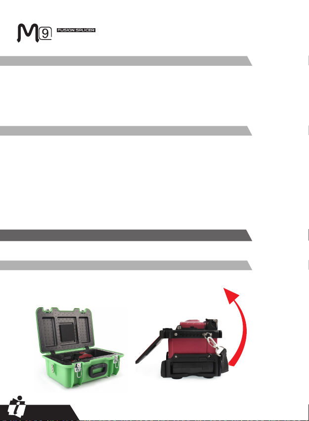
Raise the handle upwards and with a rm grip, lifting the splicer upward and out of
the carrying case. As shown below.
Important!
Please carefully follow the instructions below.
Installation upon Delivery
09
PAGE
User’s Manual
INNO Instrument, Inc.
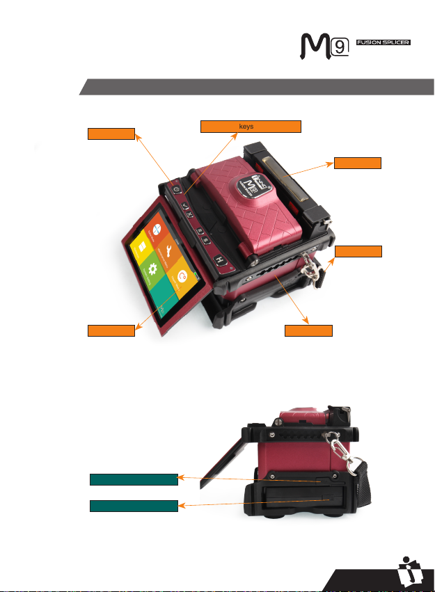
Overview of External Parts
heat oven
display battery
handle
on/off button Set/Reset keys for operation
Battery charger interface
Mini USB Interface
10
PAGE
User’s Manual
INNO Instrument, Inc.
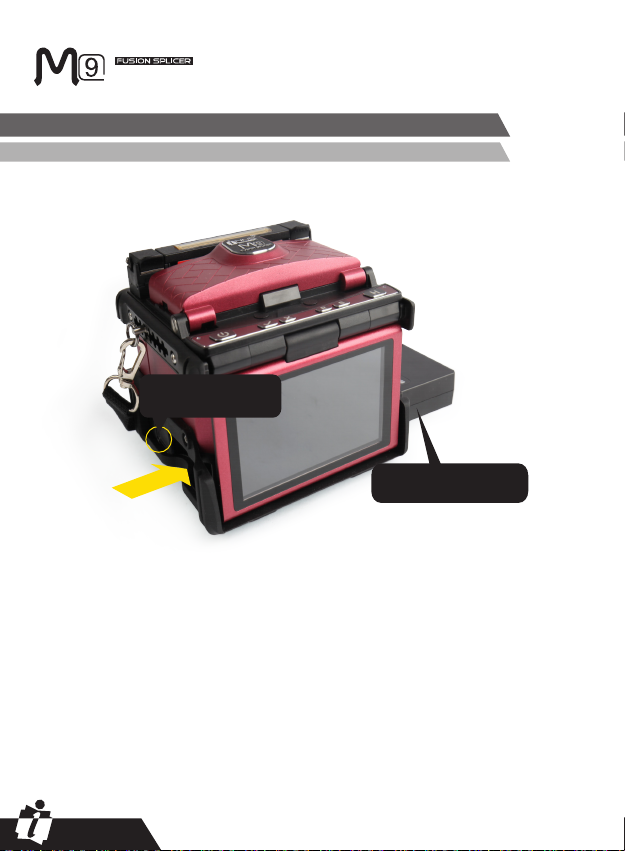
1. Following is the way of installing a battery.
Power Supply Method
Loading or unloading Battery
Shut off fusion splicer. Press on
release button at lateral, drawing
the battery out of the fusion
splicer.
Place the battery into power unit
slot until you push it into the right
place.
Draw the battery

11
PAGE
User’s Manual
INNO Instrument, Inc.
*When power supply unit is loaded on M9 fusion splicer.
*When power supply unit is detached from M9 fusion splicer.
During charging, the battery indicators will blink.
When battery charge completed, all of the indicators will be on steadily.
Loaded
There are 2 ways for viewing battery level.
① If the battery is connected to the slicer, then battery level will be displayed on the
upper right side of the screen.
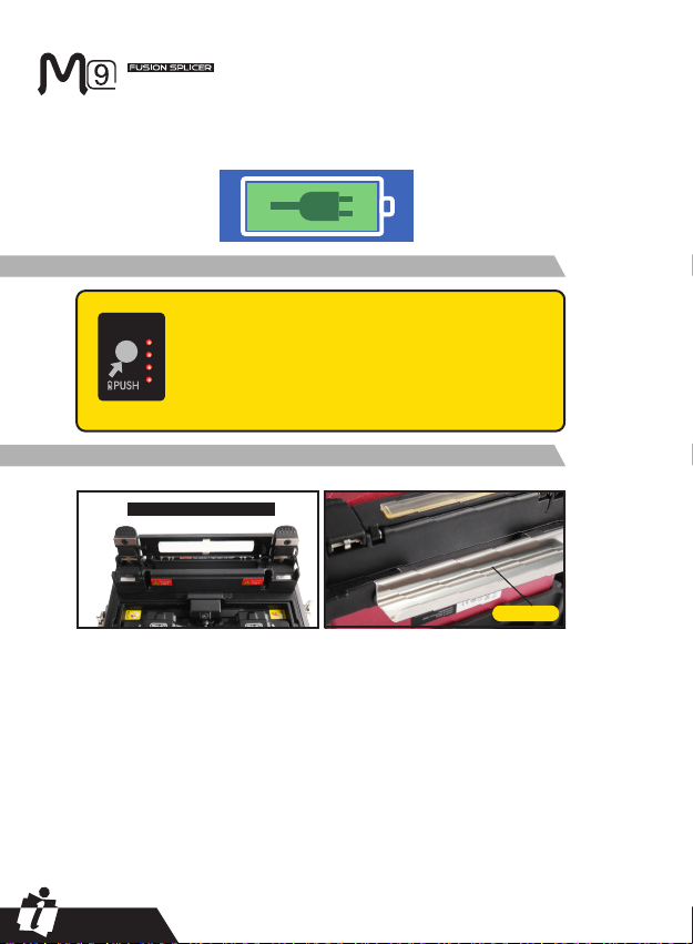
② Battery level is indicated by battery LED indicator. You can press “PUSH” to
view the battery level. As shown below:
BATTERY
INDICATOR
Charging
Battery Status
Detached
Note: 1. Before fusion splicing, please check if the remaining battery capacity is
over 20% to prevent battery capacity damage. When fusion splicing or heating
is needed but battery level is lower than 20%, please detach the battery but you
can use power adapter to support operation. 2. The temperature of battery will
increase during charging. So please do not charge for the adapter together with
battery or charge when fusion splicer is still in the carrying case.
12
PAGE
User’s Manual
INNO Instrument, Inc.
How to Install Cleaving Table
When adapter is used for power supply, a power supply indicator will be displayed
at the upper right side on the screen of fusion splicer. As shown below:
The battery should be refreshed or activated periodically for fear
of aging caused by battery memory effect. The method is as
follows:
Keep the splicer in power-on status to discharge until the splicer
switched off automatically due to completely discharging. Then
go on to charge until fully charging completes. Battery refreshing
process completes.
BATTERY
INDICATOR
Battery Refresh Cycle
Heat Oven
Open heat oven lid
cooling tray
13
PAGE
User’s Manual
INNO Instrument, Inc.
Chapter 3 - Basic Operation
Turn On the Splicer
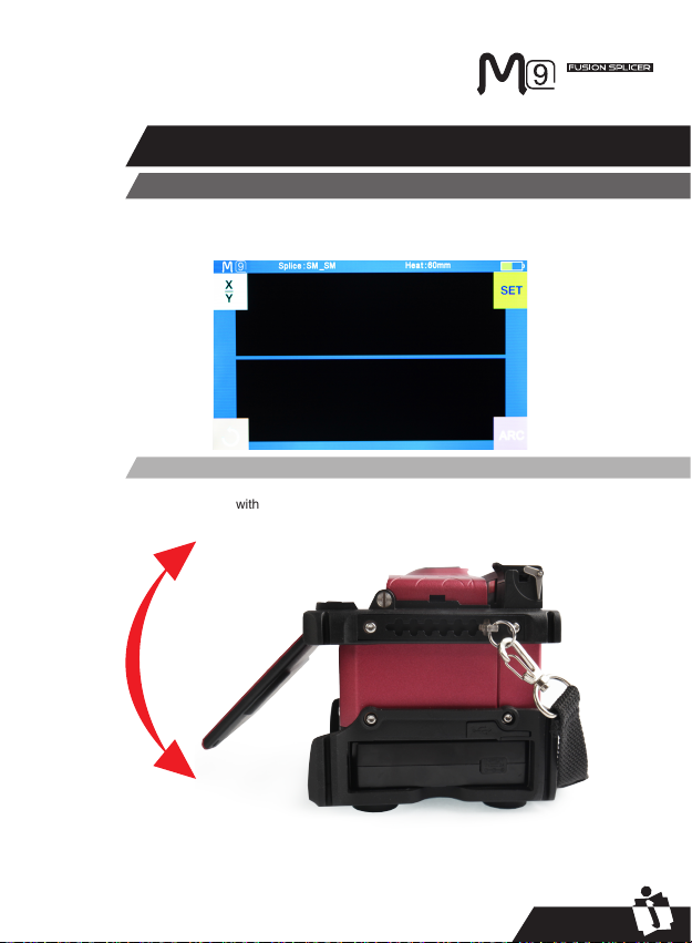
Adjust the monitor with a best angle for your convenient observation and operation
Press the “ON/OFF” button on the top left of the front operating panel of the
splicer. The READY screen of working menu (workbench) will be displayed after
startup, as shown in the following picture:
Adjust Monitor Angle

14
PAGE
User’s Manual
INNO Instrument, Inc.
In the original operating interface (workbench), press the confirmation button then
adjust LCD backlight brightness by tapping the two brightness icons on the LCD
monitor, as the following picture shows:
There are three basic preparatory steps to be completed before the fibers can be
placed in the splicer.
1) Stripping
Remove the sleeve and retain at least 50mm length of coating of optical fiber (valid
for both tight and loose tube optical fiber) with an appropriate stripper. Remove
approximately 30 to 40mm length of primary coating with an appropriate stripper.
2) Clean bare fibers with lint-free cotton tissue soaked in Alcohol.
3) How to cleave the fiber
Cleave the fibers by using a high precision cleaving tool.
To ensure good splicing, you should cleave the fibers by using a high precision
cleaver such as the cleaver of INNO V series and you should strictly control the
cleaved length well, as shown in the following picture.
Adjust LCD Backlight Brightness
Note: The LCD monitor is a precise instrument of the splicer and
it is produced in the factory under strict quality control. But there
may be dots of various colors on the screen. The brightness of
the LCD monitor depends on the monitor angle. These symptoms
are not defects of the LCD display but a natural phenomenon.
Preparing the Fiber
Note: always remember to slip a
heat-shrinkable sleeve onto either
end of the fibers at the beginning
of each fiber preparations.

15
PAGE
User’s Manual
INNO Instrument, Inc.
Important!
You must ensure to keep the fibers
clean.
- Avoid putting them down on a dusty
working surface
- Avoid waving them around in the air
- Check if the V-grooves are clean; if
not, wipe them clean with cotton swab
immersed into alcohol.
- Check whether the clamps are clean;
if not, wipe them clean with cotton swab
immersed into alcohol.
use blue V-grooves
(Clamping on bare fiber)
① Open the safety shield.
② Raise the fiber clamps.
③ Position the fibers into
V-grooves. Make sure the fiber
ends are between the V-groove
edges and the electrode tip.
④ Clamp the fiber in position by
lowering both sets of fiber clamps.
⑤ Close the safety shield.
Before continuing with splicing, you should visually check the fibers in the monitor
to make sure they are clean and well-cleaved.
How to Make a Splice
Put the optical ber in
Inspecting the Fibers
Note: Be careful not to slide the
fibers along V-grooves. When
fiber is placed into V-groove,
the fiber end should exceed
V-groove but it can’t surpass
the location of the electrode tips.
(as the following picture shows)

16
PAGE
User’s Manual
INNO Instrument, Inc.
If any defect exists in
the optical fiber, please
take out the optical fiber
carefully and prepare it
again.
① Select any desired
splice mode.
② Splice the fibers by
pressing: “SET”.
After splicing, press the key of “HEAT” to activate “shrink” process after
you have put the optical fiber sleeved with a heat shrinkable sleeve into the
heating oven, heating the heat shrinkable sleeve for purpose of strengthening and
protecting the spliced joint.
① Open the heat oven lid
② Raise left and right fiber clamps on the splicer. Hold the heat-shrink tube, lift the
spliced fibers and hold them taut, move the heat-shrink tube so that it is centered
over the splice point.
③ Move both the fibers and the heat-shrink tube over to the heat oven and place
them in the oven clamps.
④ Press the “HEAT” key to begin heating, when the heating process is finished,
the heating indicator will be turned off automatically and companied by prompt
sound of the buzzer.
Lip
Note:The fibers are checked automatically
when you press Splice button. The splicer
automatically focuses the fibers and checks
for damage or dust particles.
Note: The splicer always starts as “Auto
mode”. The splicing starts once the safety
shield is covered.
Splicing
Steps for Heating
How to Protect the Splice

17
PAGE
User’s Manual
INNO Instrument, Inc.
Heat key
Moving the ber into heat oven
position of splices
Opening the heater lid
Heating Indicator
18
PAGE
User’s Manual
INNO Instrument, Inc.
M9 fusion splicer has a concise and clear menu of splice mode, easy to be
operated. Splice modes define arc currents, splice times as well as various
parameters used when performing a splice. Therefore, it is essential to select the
correct splice mode in accordance with the type of ber you want to splice.
There is a numeric value of “pre-defined” splice modes for common fiber
combinations. However, it is also easy to either modify new splice modes to further
optimize the parameters for more unusual ber combinations.
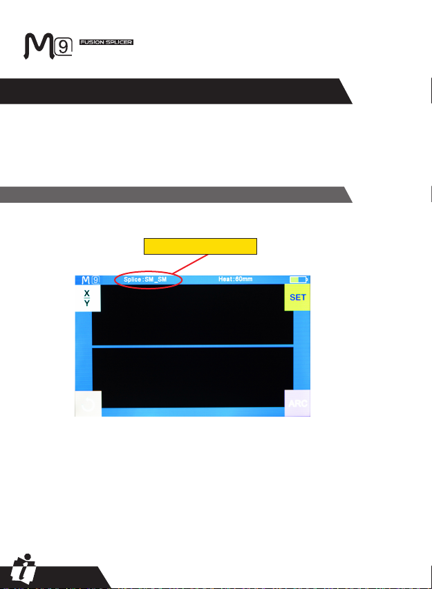
Displaying the Current Splice Mode
The active splice mode in progress at the moment is always displayed at the top of
the screen (as the picture shows).
Active splice mode currently
Chapter 4 Splice Mode

19
PAGE
User’s Manual
INNO Instrument, Inc.
①Enter main menu.
②Click “Splice Mode” for
entry.
③ Click “Select Splice
Mode” before you can
select the splice mode that
you need.
④After viewing and
selecting the splice mode,
you can press the button
of “Reset” to go back to
initial interface.
Selecting a Splice Mode
Table of contents
Other INNO Instrument Welding System manuals


Popular Welding System manuals by other brands

Miller Electric
Miller Electric SCP-200C owner's manual

Climax
Climax AUTOBOREWELDER BW3000 operating manual

Hypertherm
Hypertherm Powermax30 AIR Operator's manual

Air Liquide
Air Liquide OERLIKON CITOMIG 300 XP Safety instruction for use and maintenance

MAC TOOLS
MAC TOOLS MW13O owner's manual

Linde
Linde BOC Smoothcut 100A operating manual


 Operator's manual")


GF Piping Systems
GF Piping Systems TM 160 ECO instruction manual

SincoSald
SincoSald EVOLUTION SP3-C instruction manual

Hypertherm
Hypertherm powermax1000 Service manual

Lincoln Electric
Lincoln Electric statiflex 200-m Operator's manual

DuroStar
DuroStar DS4000WGE owner's manual

Miller
Miller GW-55C owner's manual