iNetVu Fly-1202 User manual

iNetVu®Fly-1202 User Manual
The iNetVu®brand and logo are registered trademarks of C-COM Satellite Systems, Inc.
© Copyright 2006 C-COM Satellite Systems, Inc.
1-877-iNetVu6
www.c-comsat.com
Revision 001
June 29, 2016

C-COM Satellite Systems Inc. Page 2 of 29
iNetVu®Fly-1202 User Manual
This page is intentionally left blank.

C-COM Satellite Systems Inc. Page 3 of 29
iNetVu®Fly-1202 User Manual
Copyright © 2008. All rights reserved. C-COM Satellite Systems Inc.
This document contains information, which is protected by copyright. All rights reserved. Reproduction,
adaptation, or translation without prior written permission is prohibited, except as followed under the
copyright laws.
Both the iNetVu®and C-COM names and logos are registered trademarks of C-COM Satellite Systems
Inc.
Intel®Pentium is a registered trademark of Intel Corporation. Microsoft, Windows, Windows NT and
MapPoint are registered trademarks of Microsoft Corporation.
All other product names mentioned in this manual may be trademarks or registered trademarks of their
respective companies and are the sole property of their respective manufacturers.

C-COM Satellite Systems Inc. Page 4 of 29
iNetVu®Fly-1202 User Manual
Table of Contents
1. Introduction....................................................................................................................... 5
1.1 About This Manual ....................................................................................................... 5
1.2 System Overview ......................................................................................................... 5
1.3 Power Consumption..................................................................................................... 6
2. Physical Outline ................................................................................................................ 7
3. Clearance Requirements .................................................................................................. 8
4. System Connections......................................................................................................... 9
4.1 Typical Connection with Ku Service –PC Free ............................................................ 9
4.2 Typical Connection with Ka Service –PC Free ...........................................................10
4.3 Typical Network Interface Connection - Ku .................................................................11
4.4 Typical USB Communication Interface - Ku ................................................................12
4.5 Typical USB Communication Interface - Ka ................................................................13
5. Assembly and Disassembly ............................................................................................14
5.1 Assembly Procedure...................................................................................................14
5.2 Disassembly Procedure ..............................................................................................20
6. Appendix ..........................................................................................................................25
Appendix 1. Default Limits .....................................................................................................26
Appendix 2: Compass Direction and System Ref. AZ Table ..................................................27
Appendix 3: Fly-1202 ABCD Dimensions ..............................................................................28
Appendix 4: Declaration of Conformity...................................................................................29
Proprietary Notice: This document contains information that is proprietary and
confidential to C-COM Satellite Systems, Inc., and is intended for internal and or C-COM
Satellite Systems Inc. authorized partners use only. No part of this document may be
copied or reproduced in any way, without prior written permission of C-COM Satellite
Systems, Inc.

C-COM Satellite Systems Inc. Page 5 of 29
iNetVu®Fly-1202 User Manual
1. Introduction
1.1 About This Manual
This manual explains the iNetVu®Fly-1202 Flyaway System Installation and Operation.
1.2 System Overview
Equipped to work with the iNetVu®7710 Series Controller, the iNetVu®Fly-1202
Flyaway antenna is an easily assembled, rugged and reliable product for automatic
satellite acquisition. This antenna is a rapidly deployable unit that is ideal for
applications that require satellite communication over Ku/Ka-Band. The Flyaway
empowers users with the ability to stop anywhere where satellite coverage exists and
access the Internet at broadband speeds.
The 1.2M Fly-1202 System comes with a protective case that has been designed to be
airline checkable. Without the use of any tools, the Flyaway could be field assembled
and operational in less than 10 minutes by one person.
Fig. 1: iNetVu®1202 Ku and Ka Flyaway

C-COM Satellite Systems Inc. Page 6 of 29
iNetVu®Fly-1202 User Manual
1.3 Power Consumption
Idle (Minimum) Power Consumption: 24VDC @ 0.19A for 7710 and
24VDC @ 0.13A for 7720.
Maximum Power Consumption: 7710 plus 7720
24V @ 14.6A = 350W (Max)
Controller AC Universal Input: 100 ~ 240 VAC, 50 ~ 60 Hz
(A1206A) Running Power Consumption: 24V@10A
(Max EL&AZ)
(A1206A) Maximum consumption: EL ---24VDC@10A, AZ---VDC@10A
(Stall Condition)
Fig. 2: iNetVu®7710 Controller
Fig. 3: iNetVu®7720 Remote Drive Module
The iNetVu®Fly-1202 Flyaway system offers the following additional capabilities and
features:
3-Axes (Ku-Band), 2 Axis (Ka-Band) motor drive system
Satellite acquisition within 5 minutes (under normal operating conditions)
Compatible with any configured satellite over the Ku /Ka Band
Fully automatic, software controlled satellite acquisition
Optimized signal reception and transmission
Self-calibrating and tuning after satellite acquisition
Stand Alone –Satellite Acquisition via DVB (modem independent)
Integrated with some of the leading satellite service providers available.
Easily assembled, and ruggedized transportable carry gear
C-COM Satellite Systems Inc. Page 7 of 29
iNetVu®Fly-1202 User Manual
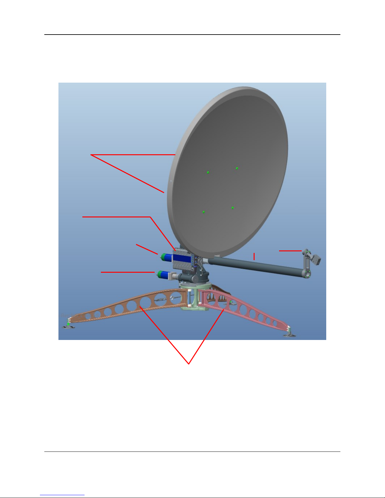
2. Physical Outline
2-piece
Detachable reflector
Feed Arm
Feed Horn
Elevation Motor
Azimuth Motor
(3) Support Legs
7720 Remote
Drive Module

C-COM Satellite Systems Inc. Page 8 of 29
iNetVu®Fly-1202 User Manual
3. Clearance Requirements
Fig. 4: Clearance requirements for the iNetVu®Fly-1201 Platform

C-COM Satellite Systems Inc. Page 9 of 29
iNetVu®Fly-1202 User Manual
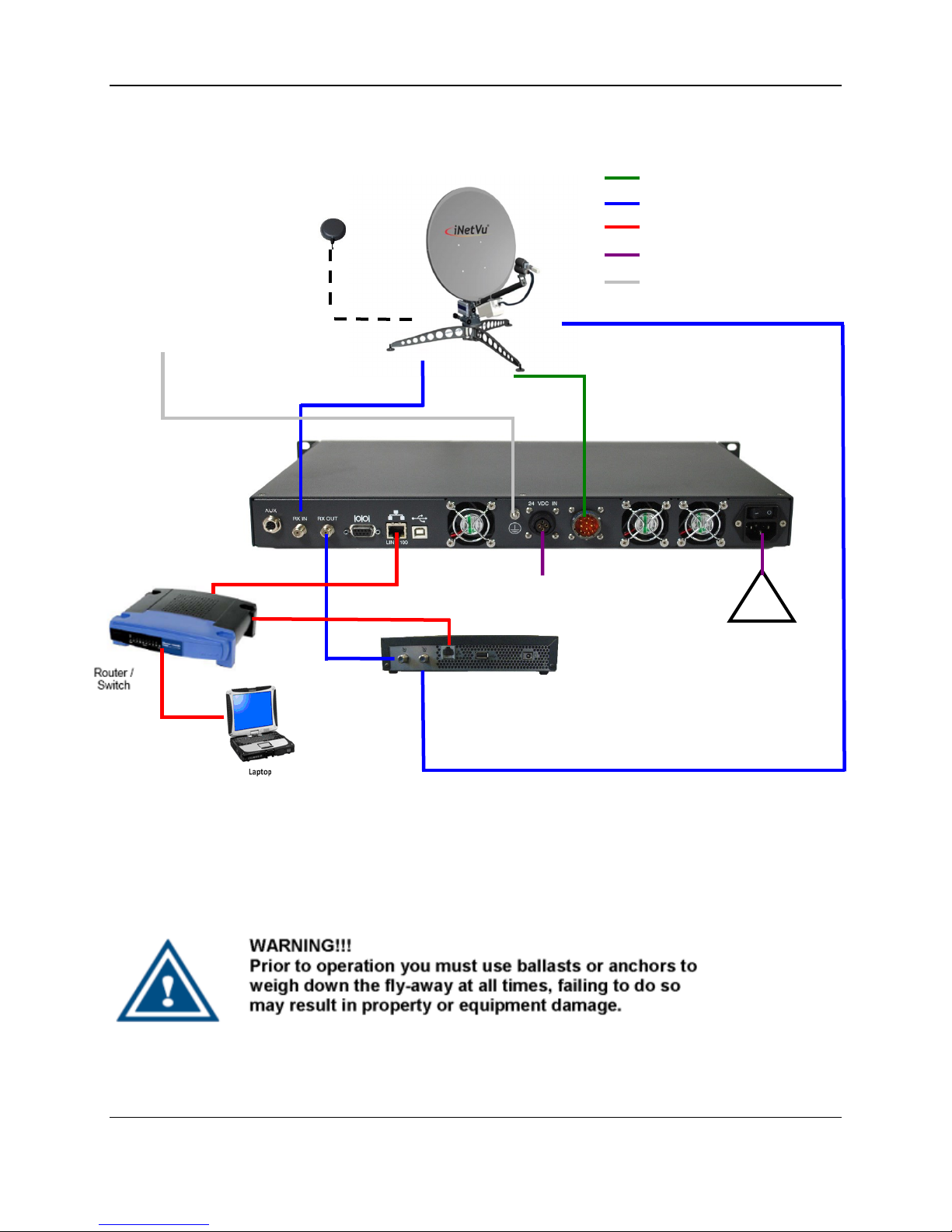
4. System Connections
The iNetVu®New Generation Flyaway (Fly-1202) Antennas have been built to
operate with the iNetVu®7710 Central Controller and a 7720 Remote (Onboard) Drive
Module. The typical connection configuration for each service will be the same
regardless of the Satellite Modem / VSAT. However, the configuration parameters for
Satellite Modem / VSAT Communication will differ depending on service. The user may
select the connection that corresponds to his/her preferred system setup prior to
configuration. The system connections shown in this section can be used with either the
Ka or Ku systems with one variable, the Ku will have two coax connections while the Ka
in most cases will only have one.
4.1 Typical Connection with Ku Service –PC Free
Fig. 5: iNetVu®7710 Controller & Ku Antenna Connection with PC Free Configuration
TX
RX
RX IN
iNetVu™
Flyaway
Platform
24 VDC Power input
(If VAC not available)
*Ground
protection
External
grounding
connection
GPS/Glonass
Antenna
!
100 - 240VAC
RX OUT
Network
Cable
RX IN
Satellite Modem / VSAT
TX OUT
COMBINED MOTOR
& DATA CONTROL
CABLE
*Recommended for proper
grounding of iNetVu®
systems.
RG6 Coaxial Cable
Combined Motor &
Data Control Cable
Network Cable
Power Cable
* Ground
Connection

C-COM Satellite Systems Inc. Page 10 of 29
iNetVu®Fly-1202 User Manual
4.2 Typical Connection with Ka Service –PC Free
Fig. 6: iNetVu®7710 Controller & Ka Antenna with PC Free Connection Configuration
*Recommended for proper grounding of iNetVu®systems.
TX
iNetVu™
Flyaway
Platform
24 VDC Power input
(If VAC not available)
*Ground
protection
External
grounding
connection
GPS/Glonass
Antenna
!
100 - 240VAC
Network
Cable
RX IN
Satellite Modem / VSAT
COMBINED MOTOR
& DATA CONTROL
CABLE
RG6 Coaxial Cable
Combined Motor &
Data Control Cable
Network Cable
Power Cable
* Ground
Connection
C-COM Satellite Systems Inc. Page 11 of 29
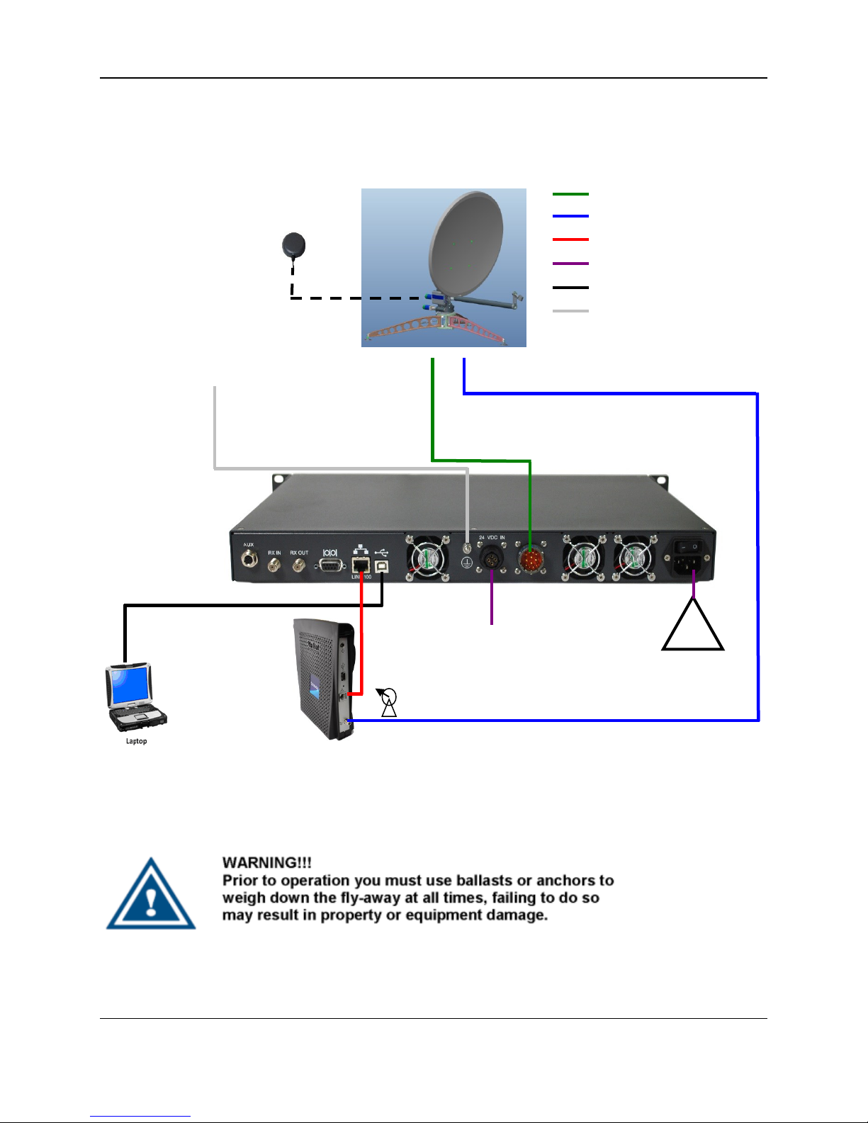
iNetVu®Fly-1202 User Manual
4.3 Typical Network Interface Connection - Ku
Fig. 7: iNetVu®LAN interface Connection Configuration with Ku Antenna
*Recommended for proper grounding of iNetVu®systems.
TX
RX
RX IN
iNetVu™
Flyaway
Platform
24 VDC Power input
(If VAC not available)
*Ground
protection
External
grounding
connection
GPS/Glonass
Antenna
!
100 - 240VAC
RX OUT
Network
Cable
RX IN
Satellite Modem / VSAT
TX OUT
COMBINED MOTOR
& DATA CONTROL
CABLE
RG6 Coaxial Cable
Combined Motor &
Data Control Cable
Network Cable
Power Cable
* Ground
Connection

C-COM Satellite Systems Inc. Page 12 of 29
iNetVu®Fly-1202 User Manual
4.4 Typical USB Communication Interface - Ku
Fig. 8: USB Interface Connection with Ku Antenna
*Recommended for proper grounding of iNetVu®systems.
TX
RX
RX IN
iNetVu™
Flyaway
Platform
24 VDC Power input
(If VAC not available)
*Ground
protection
External
grounding
connection
GPS/Glonas
s
Antenna
!
100 - 240VAC
RX OUT
Network
Cable
RX IN
Satellite Modem / VSAT
TX OUT
COMBINED MOTOR
& DATA CONTROL
CABLE
RG6 Coaxial Cable
Network Cable
Power Cable
Combined Motor & Data Control Cable
USB Cable
* Ground Connection
C-COM Satellite Systems Inc. Page 13 of 29
iNetVu®Fly-1202 User Manual
4.5 Typical USB Communication Interface - Ka
Fig. 9: USB Configuration Interface with Ka Antenna
*Recommended for proper grounding of iNetVu®systems.
TX
100 - 240VAC
!
USB Cable
*Ground
protection
External
grounding
connection
iNetVu™ Flyaway
Platform
24 VDC Power
input
(If VAC not
available)
GPS/Glonass
Antenna
Satellite Modem / VSAT
COMBINED MOTOR
& DATA CONTROL
CABLE
RG6 Coaxial Cable
Network Cable
Power Cable
Combined Motor & Data Control Cable
USB Cable
* Ground Connection
Network
Cable
C-COM Satellite Systems Inc. Page 14 of 29
iNetVu®Fly-1202 User Manual
5. Assembly and Disassembly
5.1 Assembly Procedure
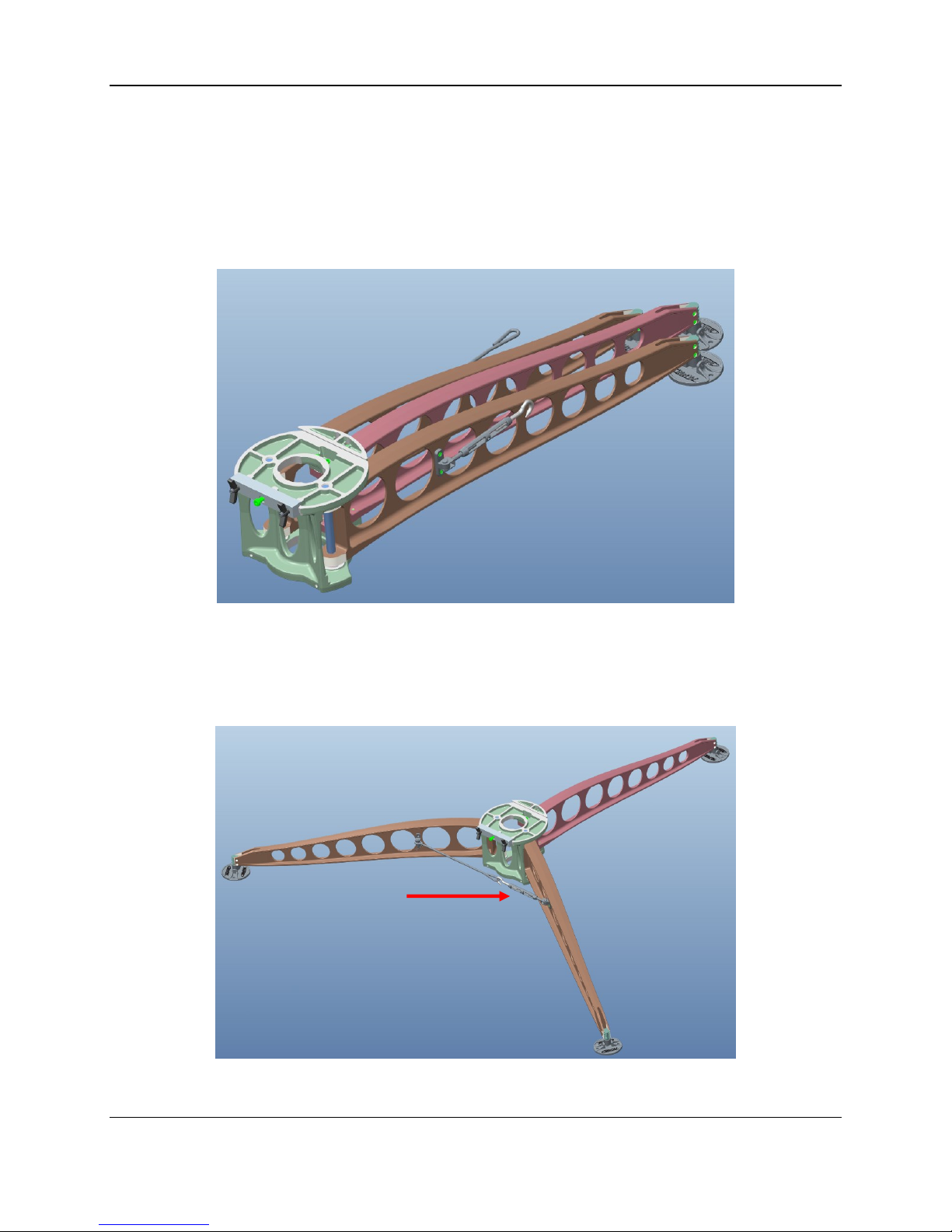
1) Open Tripod & Feed Arm case and remove Tripod.
2) Expand out Tripod legs to maximum distance until they are up against the stops,
hook turnbuckle onto tension link. Rotate Turnbuckle applying tension to lock the
legs.
Turnbuckle

C-COM Satellite Systems Inc. Page 15 of 29
iNetVu®Fly-1202 User Manual
3) Loosen Wing Clamp Handles to spring open the Dovetail Gib in order to install the
AZ/EL assembly in place.
4) Remove AZ/EL assembly from case by releasing the Cam Clamp Lever. Rotate the
Locking Arm until assembly becomes free, slowly lifting the assembly upwards.
Wing
Clamp
Handles
Dovetail
Gib

C-COM Satellite Systems Inc. Page 16 of 29
iNetVu®Fly-1202 User Manual
IMPORTANT - do not handle AZ/EL with the (7720) on-board Remote Drive
Module or drive motors during this operation as it will cause damage. Slowly
lift out AZ/EL ensuring cable does not get caught on anything inside the case.
5) Feed 7720 power and data cable through center of tripod and mount AZ/EL
assembly aligning AZ Dovetail Locking Plate on Tripod Dovetail Gib. Lock AZ/EL
assembly in place using the Dovetail Gib Wing Clamp Handles.
6) Loosen the (EL) Wing Clamp Handles on the Elevation Clamp Assembly to allow
reflector bottom segment to be installed.
EL Wing
Clamp
Handles
Elevation
Clamp
Assembly

C-COM Satellite Systems Inc. Page 17 of 29
iNetVu®Fly-1202 User Manual
7) Mount reflector bottom segment supporting it while it’s being installed. With one
hand supporting the reflector segment and with the other align and tighten the Wing
Clamp Handles on the Elevation Clamp assembly.
8) Mount top reflector segment. Lock into place using reflector Cam Clamp lever.

C-COM Satellite Systems Inc. Page 18 of 29
iNetVu®Fly-1202 User Manual
9) Install Feed Arm after removing it from case. Align locking pin on Feed Arm Socket
with Feed Arm notch. Turn Feed Arm Captive Knob to fasten.
10) Feed the IFL cable through the center of the AZ/EL drive and through the tripod
center same as was done with the Power/Data cable.
11) Connect compass cable to compass quick connect connector coming from 7720
Remote Drive Module. Line up the pins of the connector and quick connect to avoid
damaging the pins.
12) Connect Power/Data cable and IFL cable coming from 7710 controller to their
respective connections at base of antenna.
Indicates a situation or practice that might result in
property or equipment damage. Ensure Sensor, Motor
and RX/TX cables are all connected prior to powering
on 7710 Controller.
13) Plug power cable into power source and power on the controller. There should be
no blinking or RED fields on the Controls screen on the iNetView application or on
LCD.
Captive
Knob

C-COM Satellite Systems Inc. Page 19 of 29
iNetVu®Fly-1202 User Manual
14) See section (4) for controller connectivity based on your desired connection
preferences.
15) Congratulations, you have successfully assembled the iNetVu®Flyaway System
and are ready for Satellite search!

C-COM Satellite Systems Inc. Page 20 of 29
iNetVu®Fly-1202 User Manual
5.2 Disassembly Procedure
1) Click deploy Antenna icon on the iNetVu Controls screen. Antenna should deploy to
EL=30, AZ=0 and PL=0.
Reflector Assembly Removal
2) Unhook the three (3) Cam Clamp levers holding the two-piece reflector together,
and detach the top reflector assembly
3) Place top reflector section in packaging case as shown in the image; note the
positioning of the back reflector section in reference to the way it sits in the case.
4) Stow Fly-Away and power off the 7710 Controller.
Ensure to power off the 7710 Controller
prior to disconnecting cables.
Lift flap up
to place top
section in
case
Table of contents
Other iNetVu Antenna manuals


