Infatrac MS121A User manual

Wireless Industrial Alarm Adapter
User Manual
Rev. A
Issue Date: 08172015
Document Number: 00101

support@infatrac.com i © 2015 Infatrac, LLC
IMPORTANT NOTES
Device registration must be completed before installing your MS121A. You may register
online at www.infatrac.com/registration-portal.html.
These instructions are intended to be used by a professional installation technician. If
you are not a qualified professional, please be advised.
FORWARD
The Wireless Industrial Alarm Adapter (MS121A) by Infatrac focuses on providing the
best cellular alarm communicator for the security industry. Alternative communication
methods are critical due to outdated technology. Cellular alarm communicators
update industrial analog alarm panels with a stable connection, replacing one of the
dedicated landlines to the master control unit. The MS121A transmits alarm signals from
the fire panel over the cellular network to our cloud based software called Sinapsium© .
TECHNICAL SUPPORT CONTACT INFORMATION
Technical support for all Infatrac products is available:
Monday –Friday: 9am –5pm PT
Toll Free: (877) 262-6539
ABOUT THIS MANUAL
This manual assumes that you have basic security system installation skills such as
measuring voltages, stripping wire, properly connecting wires together, connecting
wires to terminals, and checking phone lines. It also assumes that you have a familiarity
with the proper installation and programming tasks related to various alarm panels.
The material and instructions covered in this manual have been carefully checked for
accuracy and are presumed to be reliable. However, Infatrac assumes no responsibility
for inaccuracies and reserves the right to modify and revise this manual without notice.
REPAIR AND WARRANTY
If trouble is experienced with the Wireless industrial Alarm Adapter (MS121A) please
contact Infatrac Technical Support for trouble shooting, repair and (or) warranty
information. The dealer or end user should not attempt any repair to the Wireless
industrial Alarm Adapter. Repair of this equipment should only be referred to qualified
technical personnel.
Infatrac will repair or replace (our option) inoperative units for up to one year from date
of manufacture. This excludes damage due to lightning or installer error. Unauthorized
modifications void this warranty. Infatrac is not responsible for incidental or
consequential damages. Liability is limited to the price of the unit. This is the exclusive
warranty and no other warranties will be honored, whether expressed or implied.
An RMA must be assigned before returning product. You may obtain an RMA via phone
at (877) 262-6539 option 2, or via email at support@Infatrac.com.
Note: RMA number must be on the outside of box or product will not be accepted.

support@infatrac.com ii © 2015 Infatrac, LLC
TERMS AND CONDITIONS FOR USE
The Wireless Industrial Alarm Adapter (WIAA) CDMA Series is an accessory to alarm
communication systems. It does not offer guaranteed protection against fire. Any alarm
communication system is subject to compromise or failure.
The Infatrac unit will not work without power. Electrically powered devices will not work
if the power supply is off for any reason, however briefly.
The cellular radio network, needed to transmit alarm signals from protected premises to
a central monitoring station, may be inoperable or temporarily out of service. Cellular
radio networks are also subject to compromise by sophisticated methods of attack.
This equipment, like any other electrical device, is subject to component failure.
Although this equipment is designed to be long lasting, the electrical components
could fail at any time.
These Terms and Conditions are a legal contract between you and Infatrac for the title
to and use of the Product. BY RETAINING AND USING THE PRODUCT YOU AGREE TO THE
TERMS AND CONDITIONS INCLUDING WARRANTY DISCLAIMERS, LIMITATIONS OF LIABILITY
AND INDEMNIFICATION PROVISIONS BELOW. IF YOU DO NOT AGREE TO THE TERMS AND
CONDITIONS, DO NOT USE THE PRODUCT AND IMMEDIATELY RETURN THE UNUSED
PRODUCT FOR A COMPLETE REFUND. You agree to accept sole responsibility for any
misuse of the Product by you; and, in addition, any negligent or illegal act or omission of
your or your agents, contractors, servants, employees, or other users of the Product so
long as the Product was obtained from you, in the use and operation of the Product.

support@infatrac.com iii © 2015 Infatrac, LLC
TABLE OF CONTENTS
1GENERAL DESCRIPTION AND OPERATION .......................................................................... 1
1.1 ALARM FORMAT SUPPORT ........................................................................................... 1
1.2 LINE SUPERVISION / LINE FAULT CONDITION .............................................................. 1
1.3 UL LISTED......................................................................................................................... 1
2INSTALLATION GUIDE ............................................................................................................. 1
2.1 STEP 1: ACTIVATION ...................................................................................................... 1
2.2 STEP 2: REGISTRATION ................................................................................................... 2
2.3 STEP 3: INSTALLATION.................................................................................................... 3
3ACCESSING THE GRAPHICAL USER INTERFACE (GUI)........................................................ 4
3.1 STEPS TO PROGRAM YOUR MS121A ........................................................................... 4
3.2 GUI COMMAND LIST ..................................................................................................... 4
3.3 FIRMWARE UPGRADE PROCESS .................................................................................. 5
3.4 ACC COMMANDS ........................................................................................................ 5
3.5 Verifying MS121A normal operation .......................................................................... 7
3.6 Periodic testing of MS121A in normal operation ............................................................ 7
4TROUBLESHOOTING ............................................................................................................. 10
5APPENDIX.............................................................................................................................. 10
5.1 PRODUCT LABEL .......................................................................................................... 10
5.2 REAR PANEL ................................................................................................................. 11
5.3 FRONT PANEL............................................................................................................... 12
5.4 DEVICE SPECIFICATIONS ............................................................................................ 13
5.5 INSTALLATION SETUP DIAGRAM................................................................................. 15
5.6 ACCESSORIES LIST ....................................................................................................... 16
6FCC COMPLIANCE STATEMENT.......................................................................................... 16
7Maintenance of MS121A backup battery ...................................................................... 17

support@infatrac.com 1 © 2015 Infatrac, LLC
1GENERAL DESCRIPTION AND OPERATION
The Wireless Industrial Alarm Adapter (MS121A) is a monitoring solution for your backup
phone line requirement on industrial Fire Alarm Control Panels (FACP). The MS121A
eliminates the phone line (POTS) connected to an alarm panel (line 2) on traditional Fire
Alarm Control Panels (FACP). The MS121A is designed to receive all alarm signal data
from your FACP by way of a Telco line interface. This data is then transmitted to a
preconfigured host server (defaulting to our Sinapsium© Monitoring Center).
1.1 ALARM FORMAT SUPPORT
The Wireless Industrial Alarm Adapter (MS121A) converts tones transmitted across line 2
of any Fire Alarm Control Panel (FACP). It is designed to capture all received fire alarm
tone signals, digitize them, and subsequently upload them to a cloud server where the
data can be parsed in any desired format. Therefore, the MS121A, as a data relaying
device, is compatible with alarm formats including but not limited to ContactID.
1.2 LINE SUPERVISION /LINE FAULT CONDITION
The Wireless Industrial Alarm Adapter (MS121A) is designed for use with all Fire Alarm
Control Panels (FACP) that do not utilize line supervision / line fault condition monitoring
on its secondary communication channel (line 2). For Fire Alarm Control Panels (FACP)
utilizing line supervision, please consult our support department for additional
specialized procedures by calling (877) 262-6539 option 2 or support@infatrac.com.
1.3 UL LISTED
The Wireless Industrial Alarm Adapter (MS121A) is UL 864 listed and certified, establishing
it as suitable for industrial and fire system applications. The MS121A is not to be used for
off-premise signaling to a supervising station.
2INSTALLATION GUIDE
Setup and installation of your MS121A is simple, straightforward, and consists of 3 steps:
activation, registration, and installation.
2.1 STEP 1: ACTIVATION
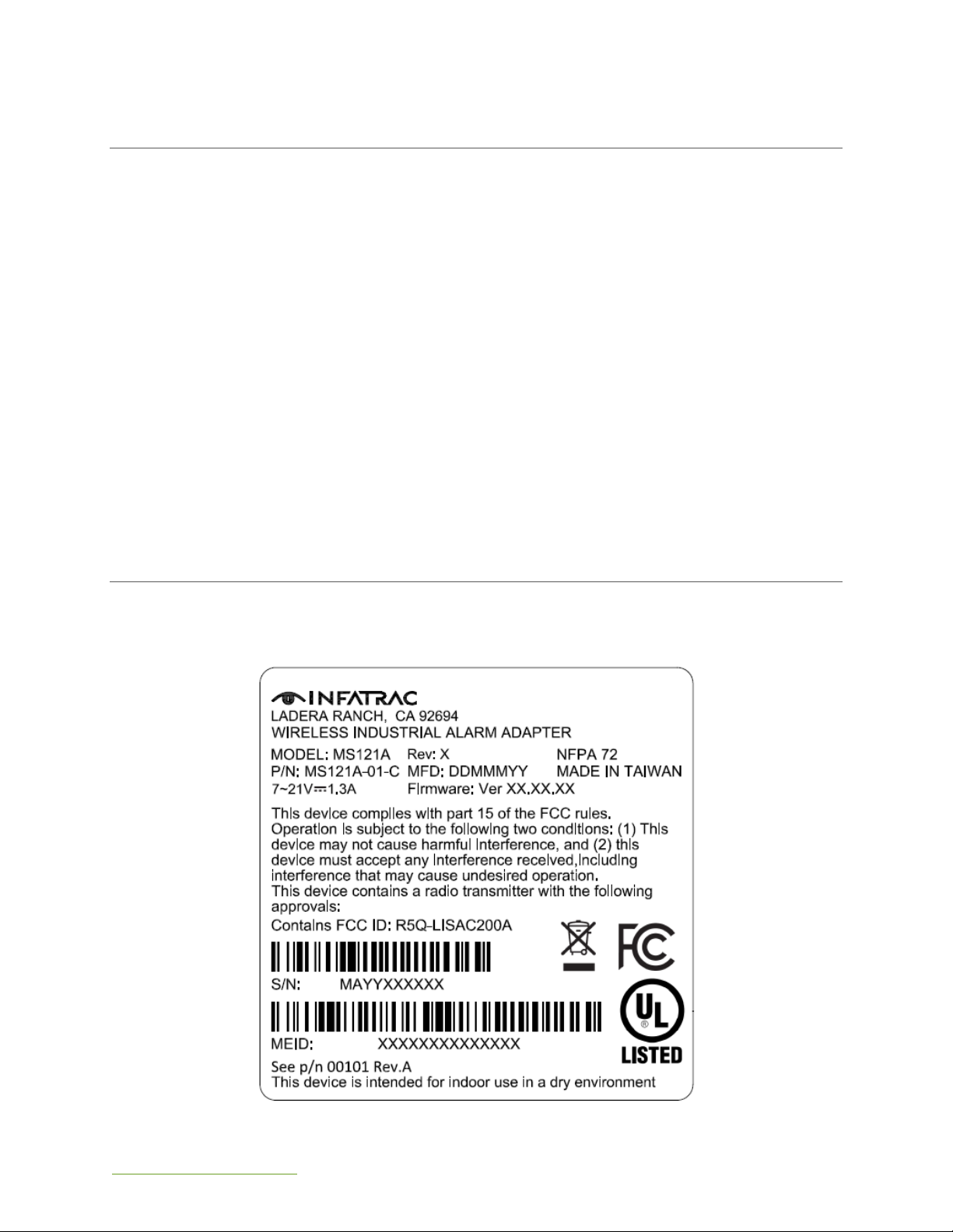
To activate your MS121A contact Infatrac by calling our toll free number (877) 262-6539.
You should be prepared to provide the MEID and Serial Number (S/N) of your MS121A,
which can be found on the label applied to the bottom of your MS121A (see Appendix
5.1).

support@infatrac.com 2 © 2015 Infatrac, LLC
To verify that your device has been activated, the Wireless Signal Strength LEDs should
indicate that your device is connected to cellular service (see Appendix 5.3). If your
device is having trouble connecting please review Section 4 –Troubleshooting or
contact support by calling (877) 262-6539 option 2 or sending us at email at
support@infatrac.com.
2.2 STEP 2: REGISTRATION
To register your MS121A to our Sinapsium© version 12.00.21 software, please visit
infatrac.com/registration-portal.html and fill out the accompanying questionnaire. After
successful registration, you will receive an email containing your username and
password with detailed instructions on how to run the Sinapsium© Dashboard on your
computer.
Once your device has successfully connected to Sinapsium© , the Server Connection
Status LED (see Appendix 5.3) should be lit red and not flashing. If your device is having
trouble connecting please review Section 4 –Troubleshooting or contact support by
calling (877) 262-6539 option 2 or sending us at email at support@infatrac.com.

support@infatrac.com 3 © 2015 Infatrac, LLC
2.3 STEP 3: INSTALLATION
Your Wireless Industrial Alarm Adapter (MS121A) should come with the following
components (for details see Appendix 5.6)
Wireless Industrial Alarm Adapter (MS121A)
DC barrel plug to terminal block
Antenna
The following components are sold separately
USB-to-USB-mini Cable
Phone Line Cable
The steps you should take to install your MS121A device are detailed as follows. For
references to the front and rear panels, see Appendix 5.2 and Appendix 5.3 in the back
of this guide.
1. Find best cellular signal: find a location for your MS121A that provides the best
cellular signal while remaining near enough to your alarm panel so that you can
run a phone line from your alarm panel to your MS121A. Also keep in mind that
you will need to connect your MS121A to your alarm panel’s 7-21VDC power
source using the included DC terminal block (see Appendix 5.6).
Note: cellular service may not be optimal in your area and a larger antenna may
be necessary to achieve optimal signal strength.
2. Mount near your alarm panel: mount your MS121A using the mounting brackets
integrated into its metal casing, making sure to leave room to access its front
and rear panels. Installation of the MS121A should be located in the same room
of the FACP.
Note 1: The antenna of MS121A must be exposed out of metal enclosure in case
of poor cellular signals. If installed the antenna inside of metal enclosure, please
use a RF switching cable to reconnect the cellular antenna out of metal
enclosure.
3. Attach antenna: attach the provided antenna to the ANT port on the rear panel
of your MS121A.
4. Plug into power (main DC AUX terminal block): Using the provided cables,
connect your device to power. For the included DC terminal block, ensure you
connect the clips to the proper terminals on your AUX 7-21VDC power source.
5. Plug into phone cable: connect your MS121A to the line 2 output from your Alarm
Panel into the PHONE LINE port on the rear panel of your MS121A.
6. Turn on: toggle the OFF ON switch on your MS121A’s rear panel to ON.
7. Wait for server connection: When the Server Connection Status LED remains on
(no longer flashing) and at least one Cellular Service light is on, your device has
successfully connected to your intended server. If you have properly activated
your device through your data provider, this process should take no more than
five minutes.
8. Trigger test alarms: Trigger test alarms from your alarm panel to verify that you
are receiving the proper text (SMS) and email alerts through your MS121A and
Sinapsium© account.

support@infatrac.com 4 © 2015 Infatrac, LLC
3ACCESSING THE GRAPHICAL USER INTERFACE (GUI)
The MS121A comes with a built-in graphical user interface (GUI) that enables users to
manually perform firmware upgrades and check a number of the MS121A’s properties
(summarized in Section 3.2 –GUI Command List). You will also be able to modify the
MS121A’s host IP and port through this menu. By default, the MS121A is shipped with the
host IP and port pointing to the Sinapsium© Monitoring Center.
3.1 STEPS TO PROGRAM YOUR MS121A
1. Connect your MS121A to a Windows XP/7/8/10 computer using a USB-mini-to-USB
cable using the USB port on your MS121A’s rear panel (see Appendix 5.2).
2. Determine the COM port your MS121A is using to communicate. Then, using a
terminal emulator (such as HyperTerminal), create a connection to your MS121A
via this COM port using the following settings:
Bits per second: 57600
Data bits: 8
Parity: None
Stop bits: 1
Flow Control: None
3. Using HyperTerminal, you will need to tell the device to display the GUI. This is
done by going under File → Properties → Settings → ASCII Setup, then selecting
the following options:
Send line ends with line feeds
Echo typed characters locally
4. In terminal window press ENTER to activate the GUI, which should look like the
following:
3.2 GUI COMMAND LIST
1. Setting –Change server IP address and Port number
2. IP Address –change server IP address
3. PORT –change server Port number
9. BACK –return to previous menu
4. Status –Displays device information (summarized in MS121A GUI - STATUS)
9. Back –return to previous menu
5. Modem Pass-through –Initiates AT command session
Type “END” to exit.
6. Firmware Upgrade –initiates firmware upgrade process
See next section, “Firmware Upgrade Process” for more details.

support@infatrac.com 5 © 2015 Infatrac, LLC
MS121A GUI –STATUS
MEID
Mobile Equipment IDentifier number
MDN
Mobile Data Number
RSSI
Received Signal Strength Indication
(dBm)
Host IP
Host server IP address
Host Port
Host server port number
Local IP
Device’s local IP address
Internet
Internet connection status (ON / OFF)
Serial No.
Serial Number
Hardware Version
Installed hardware version
Firmware Version
Installed firmware version
3.3 FIRMWARE UPGRADE PROCESS
Updating the firmware will require knowledge of a terminal emulator product such as
HyperTerminal, as well as the latest firmware file from your dealer which you can
acquire by contacting support at (877) 262-6539 Option 2.
Follow the steps in the previous section to access your MS121A’s GUI main menu. Once
there, select option 4 (Firmware Upgrade); you will have 30 seconds to send the
firmware update.
In HyperTerminal, the steps are as follows:
From menu bar select Transfer→Send File
Click Browse and select your firmware .bin file
Under Protocol select Ymodem
Press Send to start installation –a window will open showing installation progress.
When installation is complete, you will see “Programming Completed
Successfully!”
Verify in the Status menu (GUI option 2) that your firmware is now up to date.
3.4 ACC COMMANDS
Below are descriptions of commands available through option 3 (Modem Pass-through)
in the MS121A GUI.
ACC$HOSTS
DESCRIPTION
Change host connection password, type, IP address and port.
SYNTAX
Write command
ACC$HOSTS=<PASSWORD>,<TYPE>,<IP>,<PORT>
Read command
ACC$HOSTS?

support@infatrac.com 6 © 2015 Infatrac, LLC
PARAMETERS
<PASSWORD>
MS121A unable to modify password field. Use
default value.
Default : 0000
<TYPE>
UDP: 0
TCP: 1
<IP>
IP address of the host
<PORT>
TCP/UDP Port
Range: 0 –65535
RETURN VALUE
Write command
$HOSTS:OK
Read command
$HOSTS=<TYPE>,<IP>,<PORT>
Error response
$HOSTS:ERROR
EXAMPLE
UDP TYPE HOST
>>ACC$HOSTS=0000,0,123.45.67.89,5000
$HOSTS:OK
>>ACC$HOSTS?
$HOSTS=0,123.45.67.89,5000
TCP TYPE HOST
>>ACC$HOSTS=0000,1,123.45.67.89,5000
$HOSTS:OK
>>ACC$ HOSTS?
$HOSTS=1,123.45.67.89,5000
ACC$HB
DESCRIPTION
Change interval between “heartbeat” messages.
SYNTAX
Write command
ACC$HB=<TIME>
Read command
ACC$HB?
PARAMETERS
<TIME>
Time interval between “heartbeat” messages (in
seconds).
Minimum value: 60
Default value: 1800
RETURN VALUE
Write command
$HB:OK
Read command
$HB=<TIME>
Error response
$HB:ERROR

support@infatrac.com 7 © 2015 Infatrac, LLC
EXAMPLE
>>ACC$HB=3600
$HB:OK
>>ACC$HB?
$HB=3600
3.5 VERIFYING MS121A NORMAL OPERATION
Turn on GUI (see section 3.1) and press #2 on main menu, the monitor will display
device information (see below picture). RSSI should have value and Internet on if
MS121A is in normal operation.
3.6PERIODIC TESTING OF MS121A IN NORMAL OPERATION
Use ACC COMMANDS (see section 3.4) to read data via HOST IP making sure if MS121A
works normally. Recommend to implement this periodic testing in every three (3)
months.
1. Execute HyperTerminal and enter a name. For example, enter MEID number [FA0].

support@infatrac.com 8 © 2015 Infatrac, LLC
2. In “Connect To”table, enter detail HOST IP and port number. For example,
enter HOST IP: 166.143.116.154 ; host port : 59473.
3. Press ASCII setup in Settings, then check box of Send line ends with line feeds
and Echo typed characters locally.

support@infatrac.com 9 © 2015 Infatrac, LLC
4. Check internet link status, it will connect to system automatically. When the
connection is completed and left bottom of display will show connected
status. (see the below picture)
5. Get hosts remote control command –ACC$HOSTS? Leave a space before
ACC$HOSTS? and then enter to next line. Type a string following $HOST? as X,
XXX.XXX.XXX.XXX, XXXX.
X: IP type, keep “1”
XXX.XXX.XXX.XXX: HOST IP
XXXX: Port Number
Use hyper terminal, must cut/paste the typed string including the space. (see
the below pictures)
support@infatrac.com 10 © 2015 Infatrac, LLC
4TROUBLESHOOTING
The following basic troubleshooting procedures are based off the most common issues
when setting up a new MS121A. For additional troubleshooting support, please visit our
online forum.
No Wireless Signal Strength LED’s are illuminated RED
oPower-cycle the device (turn it OFF, wait 10 seconds, then turn ON)
oVerify you are within Signal Range of Verizon Wireless Towers (RSSI)
oVerify using GUI (see Section 3) that RSSI, IP and MDN information are
accurate.
oVerify that the correct server IP is selected (contact Infatrac support for
further details if using Sinapsium© )
Server Connection Status LED still flashing after 5 minutes.
oVerify using the GUI that Host IP and Port are properly set to your server.
oVerify Verizon Activation is completed and active. Contact Infatrac at
(877) 262-6539 to verify that your account is established.
No LED’s are illuminated
Ensure that power source is connected and, if applicable, internal battery is
charged.
5APPENDIX
5.1 PRODUCT LABEL

support@infatrac.com 11 © 2015 Infatrac, LLC
5.2 REAR PANEL
PORT
DESCRIPTION
ANT
Antenna connection
USB
Mini-USB connection
4-PIN
4-Pin connection –for developmental use only
PHONE LINE
Phone line connection
DC 7-21VDC
Power connection –7-21VDC current
OFF ON
Power toggle switch.

support@infatrac.com 12 © 2015 Infatrac, LLC
5.3 FRONT PANEL
FRONT PANEL LEDS
POSITION
LED
ICON
COLOR
STATE
DESCRIPTION
1ST
POWER STATUS
GREEN
ON
POWER ON
-
OFF
POWER OFF
2ND
SERVER STATUS
-
OFF
MCU FAULT
AMBER
ON
SERVER CONNECTED
AMBER
FLASHING
ATTEMPTING SERVER
CONNECTION
3RD
INTERNET STATUS
AMBER
ON
INTERNET “ON”
-
OFF
INTERNET “OFF”
support@infatrac.com 13 © 2015 Infatrac, LLC
4TH
SIGNAL STATUS
AMBER
ON
STRONG SIGNAL
AMBER
FLASHING
WEAK SIGNAL
-
OFF
NO SIGNAL
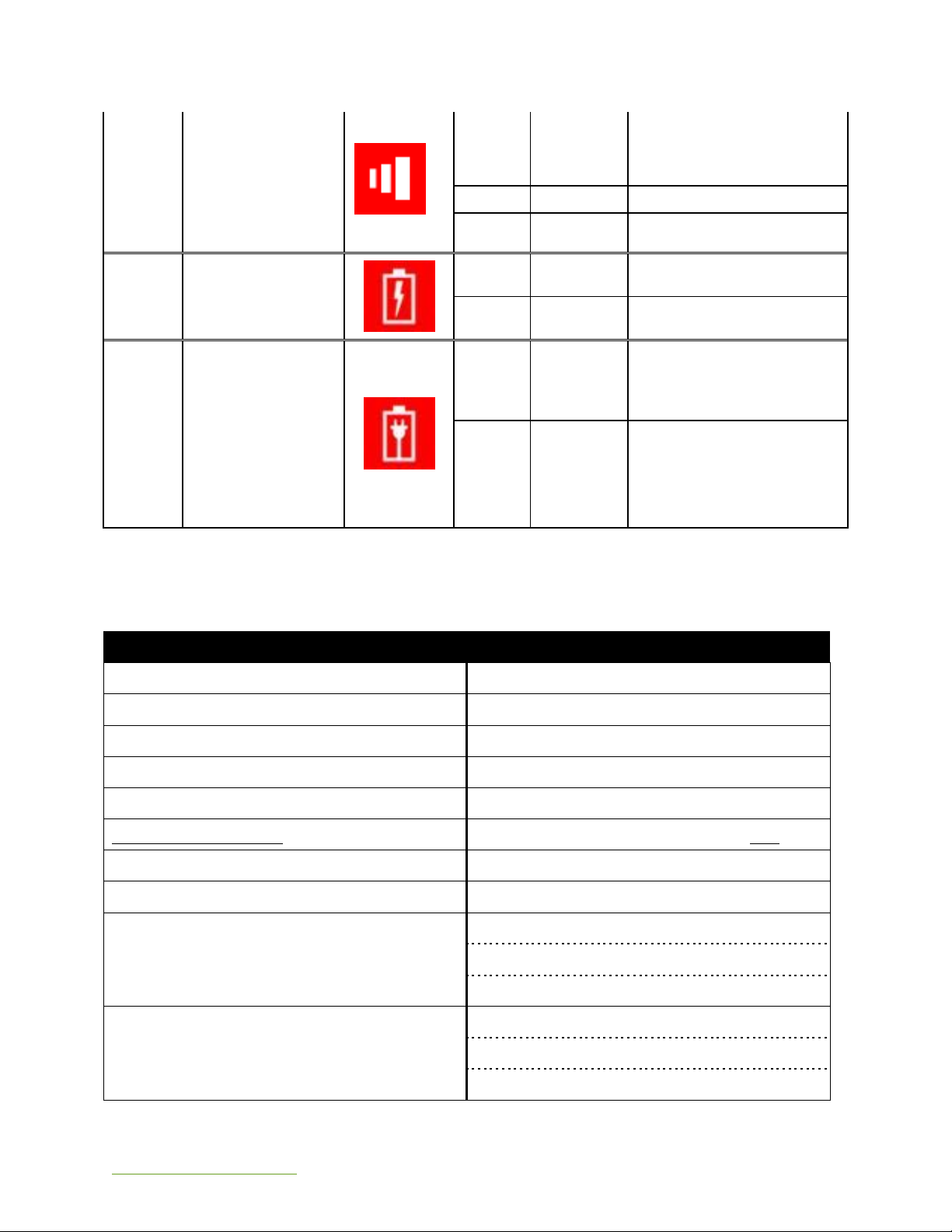
5TH
BATTERY
DISCHARGE
INDICATOR
-
ON
BATTERY CHARGING/NO
BATTERY
AMBER
FLASHING
BATTERY DISCHARGEING
(6 Hour Battery Standby)
6TH
BATTERY
INDICATOR
GREEN
ON
INTERNAL BATTERY
POWER CONNECTED
-
OFF
BATTERY
DISCHARGEING/BATTERY
FULLY CHARGED/NO
BATTERY
5.4 DEVICE SPECIFICATIONS
DEVICE SPECIFICATIONS
Power Input
7-21V DC
Power Current
Maximum 1.3A
2G/3G Module
uBlox LISA-C200
Band
800/1900 MHz
RX Sensitivity
-108 dBm
TX Power conducted
+24 dBm
Down/Uplink Speed
154 Kbps
Protocols
Embedded UDP/TP & TCP/IP & HTTP
AT Commands
Enhanced AT commands set IS-707.3
3 GPP 27.005, 3GPP 27.007, ITU-T V.25
3GPP 27.010 MUX protocol
Packet Data
Mode: Class B, Multi Slot 10
Coding Schemes: CS1-CS4
Packet Channel: PBCCH/ PCCCH

support@infatrac.com 14 © 2015 Infatrac, LLC
SMS Functionality
Text, PDU, MO/MT, Cell Broadcast
Approved Carriers
Verizon
MCU
ST Cortex M0
Flash
64 KB
SDRAM
8 KB
Frequency
48 MHz
RJ11
STMF and DTMF Tone Input
Mini-USB
RS232, Setting Parameter
Input Signal Level
Minimum: -29 dBm
Maximum: 1 dBm
Twist Accept Limit (Positive)
10 dB
Twist Accept Limit (Negative)
10 dB
Dial Tone Tolerance
18 dB
Noise Tolerance
-12 dB
Third Tone Tolerance
-16 dB
Frequency Deviation Acceptance
Max ± 1.5%
Frequency Deviation Rejection
Min ± 3.5%
Power-up Time
30 ms

support@infatrac.com 15 © 2015 Infatrac, LLC
5.5 INSTALLATION SETUP DIAGRAM
UNSUPERVISED LINE 2
SUPERVISED LINE 2

support@infatrac.com 16 © 2015 Infatrac, LLC
-MAIN SUPPLY: DC 7~21 V
-MAXIMUM Current: 1.3A
-STANDARD BATTERY Power In: DC 12V
-UNSUPERVISED LINE 2 (TELCO BRIDGE REQUIRED)
5.6 ACCESSORIES LIST
ACCESSORIES LIST
P/N
Description
# Included /
Optional
Photo
6816100993
Power terminal block
12V DC + Core 2M
1
8813000228
CE160 /
824~960,1710~2300
MHz antenna, 90°
1
6816100994
RJ11 line 1M
AWG26/4C
Optional
6816100995
USB A Type to Mini-USB
B Type Cable 60cm
Optional
6FCC COMPLIANCE STATEMENT
This equipment has been tested and found to comply with the limits for a Class B digital
device, pursuant to Part 15 of the FCC rules. These limits are designed to provide
reasonable protection against harmful interference in a residential installation. This
equipment generates, uses and can radiate radio frequency energy and, if not
installed and used in accordance with the instructions, may cause harmful interference
to radio communications. However, there is no guarantee that interference will not
occur in a particular installation. If this equipment does cause harmful interference to
radio or television reception, which can be determined by turning the equipment off
and on, the user is encouraged to try to correct the interference by one or more of the
following measures:
Table of contents
Other Infatrac Adapter manuals

Popular Adapter manuals by other brands

Connects2
Connects2 Aerpro APVPO11 manual

SMC Networks
SMC Networks SMC EZ Connect Turbo SMC2402W user guide

NETGEAR
NETGEAR WNA3100M installation guide

Logitech
Logitech SCREEN SHARE Setup guide

HandyWave
HandyWave HandyPort HPU-120 user manual

TP-Link
TP-Link 0152500174 - TL-WN321G 54Mbps 802.11g Wireless LAN USB 2.0... Quick installation guide


