infiniDome OtoSphere V2 - EPS User manual

2020
OtoSphere V2 - EPS
Installation Manual
INFINIDOME –THE WIRELESS SECURITY COMPANY

infiniDome Ltd. Web: www.infinidome.com
7 Haeshel St., Industrial Park (South) Tel: +972-4-770-7700
P.O.Box 3558, Caesarea 3088900, ISRAEL Fax: +972-4-627-0666
Contents
Introduction ............................................................................................................................................2
Interfaces ................................................................................................................................................3
Cautions ..............................................................................................................................................4
Technical Specification............................................................................................................................4
Installation ..............................................................................................................................................5
Before installation...............................................................................................................................5
Unpacking and inspecting equipment ................................................................................................5
Where to install...................................................................................................................................5
GPS Receiver System with OtoSphere ................................................................................................5
SMA Cables Connectors......................................................................................................................6
Installation procedure.............................................................................................................................6
General Operation ..............................................................................................................................8
Help and Support....................................................................................................................................9
General Specifications and Antenna Parameters ...............................................................................9
Maintenance.......................................................................................................................................9
Troubleshooting................................................................................................................................10
Problem: Nothing is working, and my GPS receiver does not acquire lock..................................10
Interference Indication .........................................................................................................................10
Interference Indication Integration Instructions ..............................................................................10

infiniDome Ltd. Web: www.infinidome.com
7 Haeshel St., Industrial Park (South) Tel: +972-4-770-7700
P.O.Box 3558, Caesarea 3088900, ISRAEL Fax: +972-4-627-0666
Introduction
Thank you for buying OtoSphere.
OtoSphere™ is a small, add-on module to any GNSS-based system that protects it from
GNSS jamming or spoofing attacks.
OtoSphere™ ensures continuity of autonomous navigation and timing signals and enables
normal operation during jamming and spoofing conditions. No other solution that offers such
protection is as small, light, affordable, easy to install or completely unregulated by export
control.
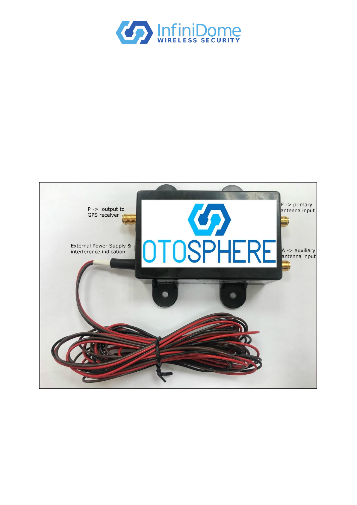
Two active GPS antennas, with nominal gain of 26dB, are connected to the SMA RF
connectors; the primary and auxiliary antenna inputs. The RF Output provides connection to the
input of the GPS Receiver.
infiniDome Ltd. Web: www.infinidome.com
7 Haeshel St., Industrial Park (South) Tel: +972-4-770-7700
P.O.Box 3558, Caesarea 3088900, ISRAEL Fax: +972-4-627-0666
Figure 1 - OtoSphere v2 - EPS - General Overview
Interfaces
(R) output to the GPS receiver SMA.
Primary Antenna Input (P) - 50Ω SMA 2.75VDC designed for 26dB ±2dB gain.
Auxiliary Antenna Input (A) - 50Ω SMA 2.75VDC designed for 26dB ±2dB gain.
Power Input:
Red: 3.5VDC –32VDC (0.75W)
Black: GND
Brown: Open drain interference indication. (This wire sends an indication when the unit
is detecting and protecting against a hostile signal).

infiniDome Ltd. Web: www.infinidome.com
7 Haeshel St., Industrial Park (South) Tel: +972-4-770-7700
P.O.Box 3558, Caesarea 3088900, ISRAEL Fax: +972-4-627-0666
Cautions
Technical Specification
Physical
Enclosure
70mm x 48 mm x 24mm (excluding mounting lugs)
Weight
150g
Mounting
4 x M3 bolts (not supplied)
Environmental
Operating Temperature
Range
-40°C to 85°C
Waterproof Rating
IP67
Safety & Compliance
R&TTE 1999/5/EC : EN60950-1, EN301 489-1, EN301 489-3, EN300 440-2
RoHS compliant
CE Compliant (PPS Version)
WEEE registration number WEE/GK2929WW
RF Interfaces
Antenna Connectors (P/A)
50Ω SMA 2.75VDC designed for 26dB ±2dB gain
Receiver Connector (R)
50Ω SMA
1. The OtoSphere unit should be mounted on a flat surface where possible and
secured using the mounting holes provided.
2. To prevent damage to any cable assemblies used in this installation, ensure
the cables are not bent, deformed or snagged to cause damage to the internal
wiring or the connector ends.
3. This product is a high-tech electronics module, installation must be
performed by a professional installer.
4. During installation ensure there is NO power applied to the module. Make
sure the GPS receiver is powered off.

infiniDome Ltd. Web: www.infinidome.com
7 Haeshel St., Industrial Park (South) Tel: +972-4-770-7700
P.O.Box 3558, Caesarea 3088900, ISRAEL Fax: +972-4-627-0666
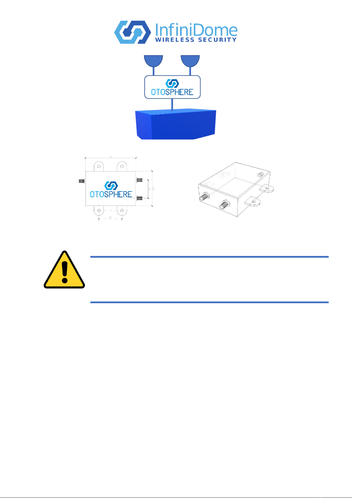
Figure 2 - GPS Receiver with OtoSphere v2 - EPS Integrated
Installation
Before installation
Please verify that the following equipment is available:
•OtoSphere V2 –EPS
•2 units of 26dB ±2dB gain antennas, 2.75VDC (from the same type) with 50Ω cable
and SMA connector (length of the cables should be identical).
•SMA coax cable from OtoSphere (R) connector to the receiver
•RF converters to SMA (if needed)
•3.5VDC –32VDC power source
Unpacking and inspecting equipment
When unpacking equipment, make a visual inspection for evidence of damage incurred during
shipment. The following parts should be included:
•(R), (P) & (A) SMA connector –please verify that the connectors are not damaged, and
the thread is complete.
•Verify that the external power supply is not damaged.
•Make sure that the unit does not have any dents.
Where to install
OtoSphere –locate and secure the OtoSphere with the power cable appropriately sized to reach
the power source and the antenna cables trimmed in equal lengths to provide adequate
separation and connection to OtoSphere unit. (See Step 2 in Installation Procedure below).
Antennas –locate and secure the antennas in full sky visibility, on the same horizontal plane,
for maximum GNSS signal reception.
GPS Receiver System with OtoSphere
The OtoSphere unit is integrated into the static or vehicle GPS receiver as shown in Figure 3.
Two antennas are connected to the module (supplied antennas or locally purchased for
permanent installation); the GPS antenna connects to primary input ‘P’ and an additional
antenna connects to the auxiliary input ‘A.’

infiniDome Ltd. Web: www.infinidome.com
7 Haeshel St., Industrial Park (South) Tel: +972-4-770-7700
P.O.Box 3558, Caesarea 3088900, ISRAEL Fax: +972-4-627-0666
Figure 3 - Unsealed vs Sealed SMA Connectors
SMA Cables Connectors
To prevent the risk of moisture ingress, it is recommended that a cable with high quality sealed
SMA connectors (see figure below) is used to connect between the OtoSphere module and the
GPS receiver unit. Please use high quality RF cables with double shielded. Single shielded
coaxial cable is not suitable. If alternative antennas are installed the same cable specification
and SMA connectors are required.
Installation procedure
Step 1. Mount OtoSphere
a) Mark out and drill four holes suitable for M3 screws.
b) Allowing for ease of cable connection, align the OtoSphere to the holes.
c) Secure the OtoSphere using appropriate fixings (not included), such as four self-
tapping M3 screws.
Step 2. Installation of the Antennas
With reference to physical installation, the location of the two antennas to be fitted is as
follows:
•Locate the antennas on a suitable area on a horizontal surface that always faces the
sky, e.g. on the roof area.
•Avoid placing the antennas near obstacles including: roof racks, other antennas such
as AM/FM and cell phone or air-conditioning devices that could block a clear view of
the sky, preventing the satellite signals from reaching the antenna.
•Ensure that there is a distance of at least 15cm between the two antennas (nominally >
25 cm).
Route the antenna cables away from moving parts, under carpet and behind plastic trim, to the
OtoSphere unit location.
infiniDome Ltd. Web: www.infinidome.com
7 Haeshel St., Industrial Park (South) Tel: +972-4-770-7700
P.O.Box 3558, Caesarea 3088900, ISRAEL Fax: +972-4-627-0666
Figure 5 - OtoSphere v2-EPS –Product Dimensions
Tips:
•Keep the cable between the OtoSphere and the GPS receiver short.
•Locate the GPS antennas as far away from other RF jamming sources as possible.
•There are large variations in the performance of GPS receivers supplied by different
manufacturers. OtoSphere adds an anti-jam capability to all receivers, but the overall
anti-jam performance of the combined system will depend on performance
characteristics of the receiver.
•OtoSphere reduces jamming signals that enter the receiver through the antenna port.
However, a poorly - designed receiver can also absorb the jamming signal through the
body of the receiver itself. A good receiver will have EMC shielding to prevent
leakage of RF radiation through its sides; if this is not the case, and a better receiver
can’t be used, install the receiver in a shielded case.
•If possible, increase the distance between the OtoSphere antennas and any jamming
source. For example, if there is a jammer operating from the cigarette lighter socket in
a car, locate the antennas towards the rear of the vehicle.
GPS antenna
GPS antenna
GPS Receiver
Figure 4 - OtoSphere v2-EPS - Operational Diagram
To prevent damage to any cable assemblies used in this
installation, ensure cables are not bent, deformed or
snagged to cause damage to the internal wiring or the
connector ends.

infiniDome Ltd. Web: www.infinidome.com
7 Haeshel St., Industrial Park (South) Tel: +972-4-770-7700
P.O.Box 3558, Caesarea 3088900, ISRAEL Fax: +972-4-627-0666
•If OtoSphere is installed in a complex environment, such as a vehicle, experiment with
the placement and orientation of the antennas for best results. Due to the complex
propagation environments within vehicles, different installation options may produce a
higher or lower performance.
Step 4. Coax cabling
Connect and secure the following cables to the OtoSphere unit using an SMA torque spanner
set to 1Nm (8.85 in-lbs):
a) Antenna 1 cable connector to the auxiliary antenna input ‘A’ connector.
b) Antenna 2 cable connector to the primary antenna input ‘P’ connector.
c) The RF output to receiver ‘R’ connector using a locally sourced cable fitted with high
quality sealed SMA connectors. The other end connected into the GPS receiver RF
antenna input.
Step 5. External power supply
Verify that the DC provided on the receiver cable is 3.5VDC - 32VDC and can provide at
least 800mW of power.
a) Connect the red wire to +V (3.5VDC –32VDC).
b) Connect the black to common (GND).
c) When interference indication is required, use the brown wire (and the same common –
black), in accordance with interference indication.
Step 6. Coil and secure any excess of antenna cable and power wires into a hidden location,
such as under the carpet, using wire ties (not supplied).
General Operation
OtoSphere unit operates without manual intervention.
Two LEDs located on the OtoSphere unit, provide the following indications:
LED 1 –When the module is powered ON and operating correctly, a green LED is steady on.
LED 2 –When the presence of a jamming event is detected, a red LED is steady on.
Caution: Make sure you connect the DC + to the red wire and
the common/ground to the black wire.

infiniDome Ltd. Web: www.infinidome.com
7 Haeshel St., Industrial Park (South) Tel: +972-4-770-7700
P.O.Box 3558, Caesarea 3088900, ISRAEL Fax: +972-4-627-0666
Help and Support
General Specifications and Antenna Parameters
Table 1 - General Specifications
Item
Parameter
Description/notes
Value
Units
Min.
Typ.
Max
Physical Operational Environmental
1
Temperature
range
-40
25
+85
˚C
Default System Configuration
RF Specification
2
Protected
frequency
GPS L1
1575.42
MHz
Power Supply Specification
3
Supply
Voltage
Receiver DC line
+3
+32
Volt
4
Supply
Consumption
Including antennas
0.75
Watt
5
Antenna Bias
Voltage
2.75
Volt
Current per o/p
10
25
mA
Self re-setting fuse
200
mA
Table 2 - Antenna Parameters
Item
Description
Value
Units
Min.
Typ.
Max.
Type
Active GPS Patch
n/a
Elements
2
n/a
Gain
30
dB
Noise Figure
2
dB
Supply Voltage
2.75
Volt
Supply Current
2
10
20
mA
Maintenance
OtoSphere does not contain any user-serviceable parts and contains no moving parts. With
reference to the CAUTIONS on page 3, no maintenance is required apart from examining all the
cable assemblies for secure connection, damage and corrosion.
infiniDome Ltd. Web: www.infinidome.com
c/o Focus Telecom Ltd. Mail: info@infinidome.com
7 Haeshel St., Industrial Park (South) Tel: +972-4-770-7700
P.O.Box 3558, Caesarea 3088900, ISRAEL Fax: +972-4-627-0666
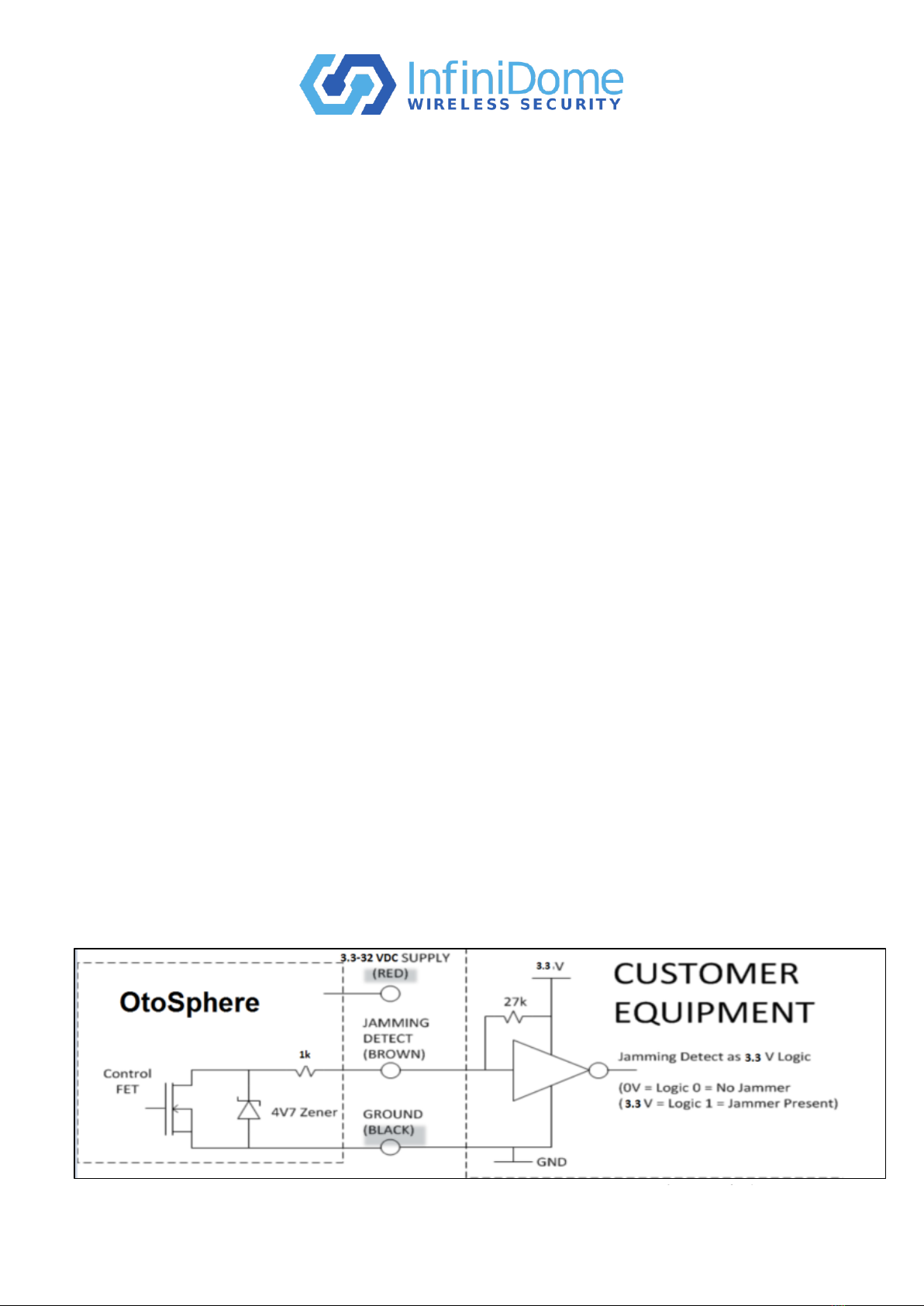
Figure 6 - Jamming Interference Detection Output Circuit
Troubleshooting
Problem: Nothing is working, and my GPS receiver does not acquire lock
Complete the following steps, in order:
•Check that there are no obstructions (e.g. buildings, tunnels) around or above the
installation; move to another location as necessary.
•Isolate any internal jamming sources; switch off all other electronic devices.
•Check all cable connections for damage, excessive bending and that they are correctly
secured.
•Check the GPS receiver functions correctly when connected directly to ONE antenna,
without OtoSphere connected. Repeat with the other antenna. If both antennas are
confirmed as OK, then reconnect OtoSphere.
•Check that the antennas are connected to OtoSphere ‘P’ and ‘A’ connectors, and that
the SMA connectors are tightened.
•Check that the OtoSphere ‘R’ connector is connected to the GPS receiver, and that the
SMA connectors are tightened at both ends.
•Check that 3.5VDC - 32VDC external power is connected from the OtoSphere to an
applicable power source.
•Check that the green LED is ON when an active GPS receiver is connected
Interference Indication
Indication specification
Detection bandwidth: 1540MHz - 1602MHz
Detection threshold: approximately -110dB (dependent on environmental factors)
The custom integrated circuit at the core of OtoSphere has an open drain output to indicate the
presence of jamming or spoofing events. Its switch point is a function of external antenna
LNA gain and so cannot be precisely specified.
Note: Please note that this connection is optional
Interference Indication Integration Instructions
The open drain circuit inside OtoSphere (left hand side of Figure 1) connects to the “brown”
wire. In case of reception without jamming or spoofing, the Control FET is off, and the
jamming detect wire is open circuit for DC voltages applied up to wire. When jamming is
detected, the Control FET connects the internal 1k resistor to ground.
In order to translate the interference indication (brown wire) to logic level signal, connect the
brown wire to DC voltage in the customer equipment via pullup resistor.
infiniDome Ltd. Web: www.infinidome.com
7 Haeshel St., Industrial Park (South) Tel: +972-4-770-7700
P.O.Box 3558, Caesarea 3088900, ISRAEL Fax: +972-4-627-0666
PPS installation
Installation of the PPS unit is very similar to the EPS unit.
The only difference is that the PPS unit receives its power
from the “R” connector, which can be supplied from either
the receiver or from indiniDome’s Power over RF (PoRF)
component.
The receiver must supply the PPS unit with power between
3.5VDC-32VDC in, min current of 0.8W, If the receiver
cannot supply this, we can recommend providing the PPS
unit power from PoRF.
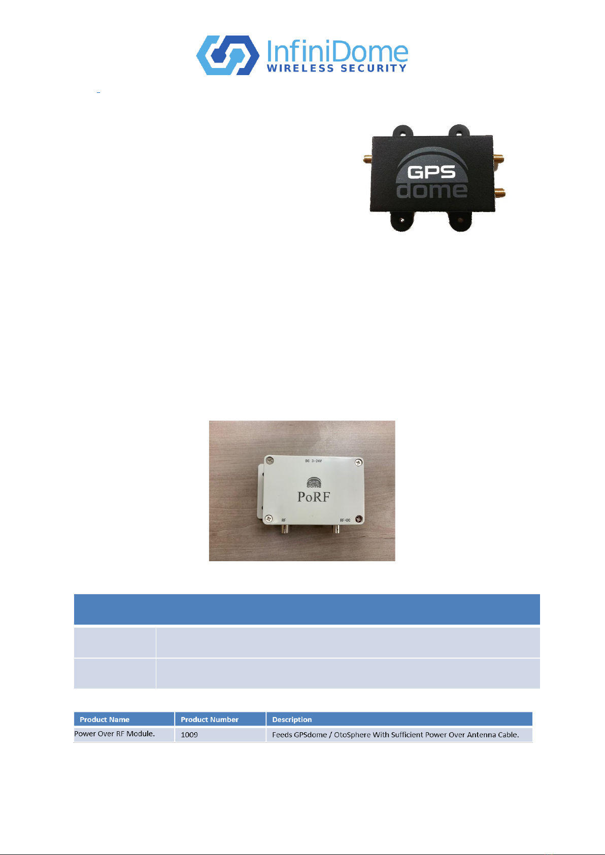
PoRF
the PoRF module provides power (DC) to the PPS (Phantom Power Supply) unit over the RF cable. As
most installations of PPS units are on a roof of a building where no power source is available, the
PoRF enables the OtoSphere to be sufficiently powered over the RF cable.
The PoRF unit is mounted next to the GPS receiver or timing server. It is connected to the antenna
port on the receiver, connected to a power supply via DC input, and connected to the antenna cable
going to the roof where it will be connected to the OtoSphere unit.
specification:
Interfaces
RF Connectors
BNC (F)
Power (3-24V)
3-24VDC (MATING PLUG 5.5mm * 2.1-2.5mm)
Ordering Information
Table of contents


