Infinite Transtector TT-WM8-4G-4GP+ User manual

Industrial 8-port 10/100/1000T
Wall-mounted Industrial Gigabit
Ethernet Switch with 4-Port PoE+
Model: TT-WM8-4G-4GP+
User's Manual

1. Package Contents
Thank you for purchasing TT-WM8-4G-4GP+ industrial 8-port 10/100/1000T Wall-mounted Gigabit Ethernet Switch.
Model Name
10/100/1000T
Copper Ports
802.3at PoE+
Ports
Power Adapter
TT-WM8-4G-4GP+
8
4
DC 54V, 1.33A
In the following section, unless specified, the term “Wall-mount Gigabit Switch” mentioned in this user’s manual
refers to the above mode
Open the box of the Wall-mount Gigabit Switch and carefully unpack it. The box should contain the following items
The Wall-mount
Gigabit Switch x 1
RJ45 Dust Cap x 8
Wall-mounted Kit x 1
DIN-rail Kit x 1
Magnet Kit x 1
Power Cord x 1
Power Adapter x 1

2. Hardware Description
2.1 Switch Front View
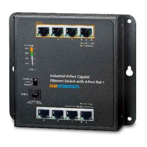
The front panel of the Wall-mount Gigabit Switch consists of 8 Auto-Sensing 10/100/1000Mbps Ethernet RJ45 Ports.
The LED Indicators are also located on the RJ45 ports of the Wall-mount Gigabit Switch.
TT-WM8-4G-4GP+ Front View
2.2 LED Indicators
■System and Ports
LED Color Function
PWR Green Lights to indicate that the Switch has power.
LNK/ACT
Green
Lights
To indicate the link through that port is
successfully established.
Blinks
To indicate that the switch is actively sending or
receiving data over that port.
PoE-in-
Use Amber
Lights
To indicate the port is providing DC in-line
power.
Off
To indicate the connected device is not a PoE
powered device (PD).

■PoE Power Usage (Unit: Watt)
LED
Color
Function
15 Amber
Off To indicate the PoE usage is less than 7W.
Blinks To indicate the PoE usage is around 8W to 14W.
Lights
To indicate the PoE usage is over 15-watt PoE
power budget.
30 Amber
Blinks To indicate the PoE usage is around 23W to 29W.
Lights To indicate the PoE usage is over 30-watt PoE
power budget.
45 Amber
Blinks To indicate the PoE usage is around 38W to 44W.
Lights:
To indicate the PoE usage is over 45-watt PoE
power budget.
60 Amber
Blinks To indicate the PoE usage is around 53W to 59W.
Lights:
To indicate the PoE usage is at the maximum.
2.3 DIP Switch
The front panel of Wall-mount Gigabit Switch provides one DIP switch for Standard, VLAN and Extend mode
selections. The detailed descriptions are shown in the following table.
DIP Switch Mode Function
This mode makes the Wall-mount Gigabit Switch
operate as a general switch and all ports operate
at 10/100/1000Mbps auto-negotiation.
This mode makes the Wall-mount Gigabit Switch
operate as a VLAN isolation switch and
1. Port 1 to port 6 will isolate respectively.
2. Port 1 to port 6 will only communicate with port
7 and port 8 (uplink ports).
This mode makes the Wall-mount Gigabit Switch
operate as a VLAN isolation switch and
1. Port 1 to port 6 will isolate respectively.
2. Port 1 to port 6 will only communicate with port
7 and port 8 (uplink ports).
3. 22~25-watt PoE transmit distance of 250m at
speed of 10Mbps.
Please reboot the Wall-mount Gigabit Switch after adjusting the
DIP switch.

2.4 Physical Dimensions
WxDxH: 148 x 24.2 x 134 mm
Model number may or may not be permanently screen printed on
front of unit.

3. Installation
3.1 Wall-mount Installation
To install the Wall-mount Gigabit Switch on the wall, simply follow the following steps:
Step 1: Place the Wall-mount Gigabit Switch on the wall and mark the four holes with a pencil.
Step 2-1: Hammer the anchors provided into the four holes and use the four screws to tightly fix the switch onto the
wall by screwing them in.

Step 2-2: Or the Switch, as shown in the picture below, can be hung on the wall by screwing the two screws leaving a
space of 2mm apart after the anchors are hammered in.
3.2 DIN-rail Mounting Installation
The DIN-rail kit is included in the Wall-mount Gigabit Switch package. To hang up the Wall-mount Gigabit Switch,
follow the steps below:
Step 1: Screw the DIN-rail bracket on the Wall-mount Gigabit Switch.
Step 2: Lightly press the bottom of DIN-rail bracket into the track.
Step 3: Check whether the DIN-rail bracket is tightly on the track.

3.3 Magnet Installation
To install the Wall-mount Gigabit Switch on a magnetic surface, simply follow the following diagram:

4. Customer Support
Thank you for purchasing Transtector products. You can browse our online resources and User’s Manuals on www.
Transtector.com. If you require sales or support information, please contact the Transtector support team using the
information found below or using Transtector’s online chat tool.
Transtector
10701 Airport Road
Hayden, Idaho 83835
USA
Toll Free: (800) 882-9110
International: (208) 635-6400
www.Transtector.com

Appendix: Product Specifications
Model
TT-WM8-4G-4GP+
Hardware Specifications
Network Port Type
8x RJ45 with 10/100/1000BASE-T
Auto-negotiation and auto MDI/MDI-X
PoE Capable Ports
4
Power Requirements
48~56V DC, 1.5A max.
Power Consumption 70 watts/
239 BTU
ESD Protection
4KV DC
Surge Protection
6KV DC
DIP Switch Options
Selectable operation mode
- Standard / VLAN / Extend
Enclosure Type
IP30 metal
Dimensions
148 x 24.2 x 134 mm (W x D x H)
Weight
472 g
Switch Specifications
MAC Address Table
4K MAC address table with auto learning function
Data Buffer
64Kbytes
Switch Fabric
16Gbps
Switch Throughput
11.9Mpps@64bytes
Flow Control
Back pressure for half duplex.
IEEE 802.3x pause frame for full duplex
Power over Ethernet
PoE Standard
IEEE 802.3at Power over Ethernet Plus PSE
Backward compatible with IEEE 802.3af PoE
PoE Type
End-span PSE
Power Pin Assignment
1/2(+), 3/6(-)
PoE Power Output Per port 52V~54V DC, 30 watts (max.)
PoE Power Budget
60 watts
Standard Conformance
Standard Compliance
IEEE 802.3
IEEE 802.3u
IEEE 802.3ab
IEEE 802.3x
IEEE 802.3af
IEEE 802.3at
Ethernet
Fast Ethernet
Gigabit Ethernet
Flow Control
Power over Ethernet
Power over Ethernet Plus

IEEE 802.3az
Energy Efficient Ethernet (EEE)
Regulatory Compliance
FCC Part 15 Class A, CE
Environment
Operating
Temperature: -10 ~ 60 degrees C
Relative Humidity: 5 ~ 95% (non-condensing)
Storage
Temperature: -20 ~ 70 degrees C
Relative Humidity: 5 ~ 95% (non-condensing)
Energy Saving Note of the Device – AC Adapter
This power required device does not support Standby mode operation. For energy savings, please
remove the AC adapter from the device for power disconnection. Without removing the AC Adapter, the
device will still consume power from the power source. In the view of Saving the Energy and reducing the
unnecessary power consumption, it is strongly suggested to remove the AC adapter from the device if
this device is not intended to be active.
Table of contents
Other Infinite Network Router manuals
Popular Network Router manuals by other brands
ZyXEL Communications
ZyXEL Communications MES3500-24F user guide
D-Link
D-Link DVA-G3670B Quick installation guide

Blankom
Blankom 5161.20 Device manual
TRENDnet
TRENDnet TW-H6W1IR Specifications
D-Link
D-Link DES-1005P Quick installation guide
TP-Link
TP-Link TL-WR1043ND - Ultimate Wireless N Gigabit... Quick installation guide
