800.882.9110 | 208.772.8515 | www.transtector.com
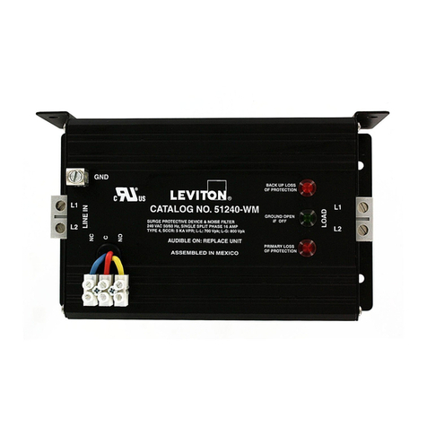
DRDC Series
1. These products are intended for use only on data & power circuits with operating voltage not
to exceed the product rating (see chart on reverse), and operating currents not to exceed 10A.
The DRDC products are approved for use in nonincendive equipment in Class I, Division 2,
Groups A, B, C and D; equipment protection by non-sparking equipment AEx/Ex nA for use in
Class I, Zone 2, Group IIC, hazardous (classied) locations; and ordinary (unclassied) locations
with an ambient temperature rating of -40°C to +65°C, indoor environments.
2. Installing the DRDC Series
2.1 In types of protection suitable/non-sparking equipment, the surge suppressor (DRDC
Series) equipment is designated with the following specic conditions of use: The equipment
shall be installed in compliance with the enclosure, mounting, spacing and segregation
requirements of the ultimate application, including a tool removable cover.
2.1.1 In types of protection non-sparking equipment, the component protector (DRDC
Series) equipment is designated with the following specic conditions of use:
When installed as category 3 equipment the DRDC Series surge suppressor shall be
mounted within a tool secure enclosure which meets the requirements of EN 60079-0 and
EN 60079-15 and is capable of accepting the applicable wiring methods specied in
EN 60079-14. When installed in outdoor or potentially wet locations, the enclosure shall,
at a minimum, meet the requirements of IP54. When installed in locations providing
adequate protection against the entry of solid foreign objects or water capable of
impairing safety, the enclosure shall, at a minimum, meet the requirements of IP4X. The
nal enclosure shall not contain more than 7.5% in total magnesium.
2.2 Mount the device as close as possible to the equipment to be protected.
2.3 Mounting, Mechanical: Install the product onto standard 35mm DIN-Rail using the Self
Grounding foot. Engage the metal grounding clip onto the rail rst, then snap into place. To
remove the device, apply force on the lever provided on the foot using a athead screw driver.
Note: Din-Rail must be connected to a solid Earth ground for proper suppressor operation.
2.4 Wiring: Connect each DC power or signal pair to the numbered 24-12AWG screw
terminals according to the following legend (Input->Output):
Pair 1 Pair 2
1->7 3->5
2->8 4->6
2.5 Wiring the Shield: If a shielded cable is utilized, use the pass-thru terminal blocks
contained in the packaging supplies to secure the shield for each pair.
2.6 Molded from R/C (QMFZ2), Cat. No. B3UG4, designated Ultramid manufactured by
BASF Aktiengesellschaft.
3. Replacing DRDC Series Suppressor Modules
3.1 Annunciation: In the case of failure, the suppressor module will interrupt the DC power\or
signal path.
3.2 Replacing the module: To replace the suppressor module, simply pull the failed module
out of the base and reinstall a new one ensuring that the module is correctly oriented with the
slot in the base.
1200-144 REV K
