manuals.online logo
Brands
  1. Home
  2. •
  3. Brands
  4. •
  5. M-system
  6. •
  7. Surge Protector
  8. •
  9. M-system MD7LC User manual

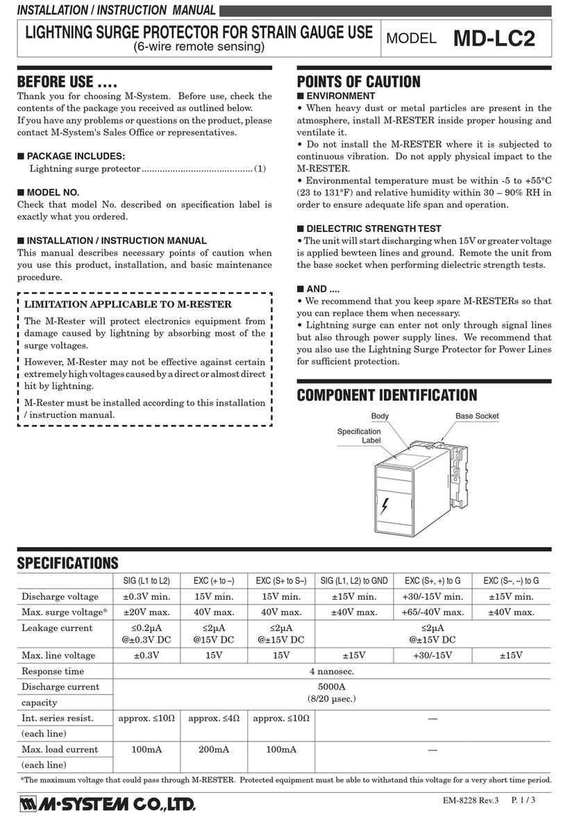
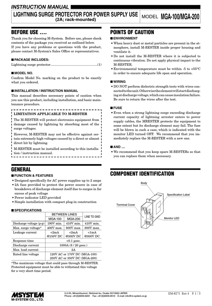
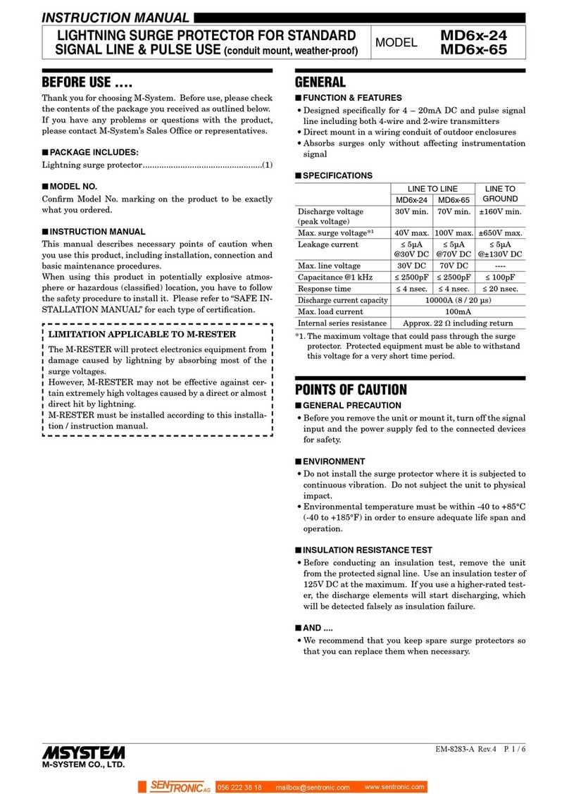
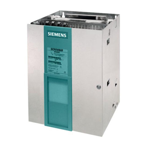
M-system MD7LC User manual

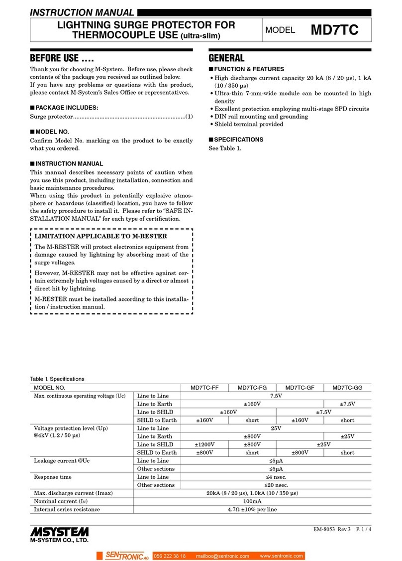
EM-8063 Rev.3 P. 1 / 4
INSTRUCTION MANUAL
LIGHTNING SURGE PROTECTOR FOR
STRAIN GAUGE (ultra-slim) MODEL MD7LC
BEFORE USE ....
Thank you for choosing M-System. Before use, please check
contents of the package you received as outlined below.
If you have any problems or questions with the product,
please contact M-System’s Sales Office or representatives.
■PACKAGE INCLUDES:
Surge protector....................................................................(1)
■MODEL NO.
Confirm Model No. marking on the product to be exactly
what you ordered.
■INSTRUCTION MANUAL
This manual describes necessary points of caution when
you use this product, including installation, connection and
basic maintenance procedures.
When using this product in potentially explosive atmos-
phere or hazardous (classified) location, you have to follow
the safety procedure to install it. Please refer to “SAFE IN-
STALLATION MANUAL” for each type of certification.
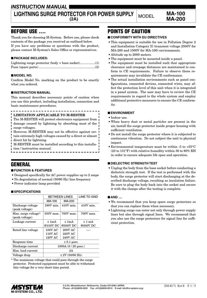
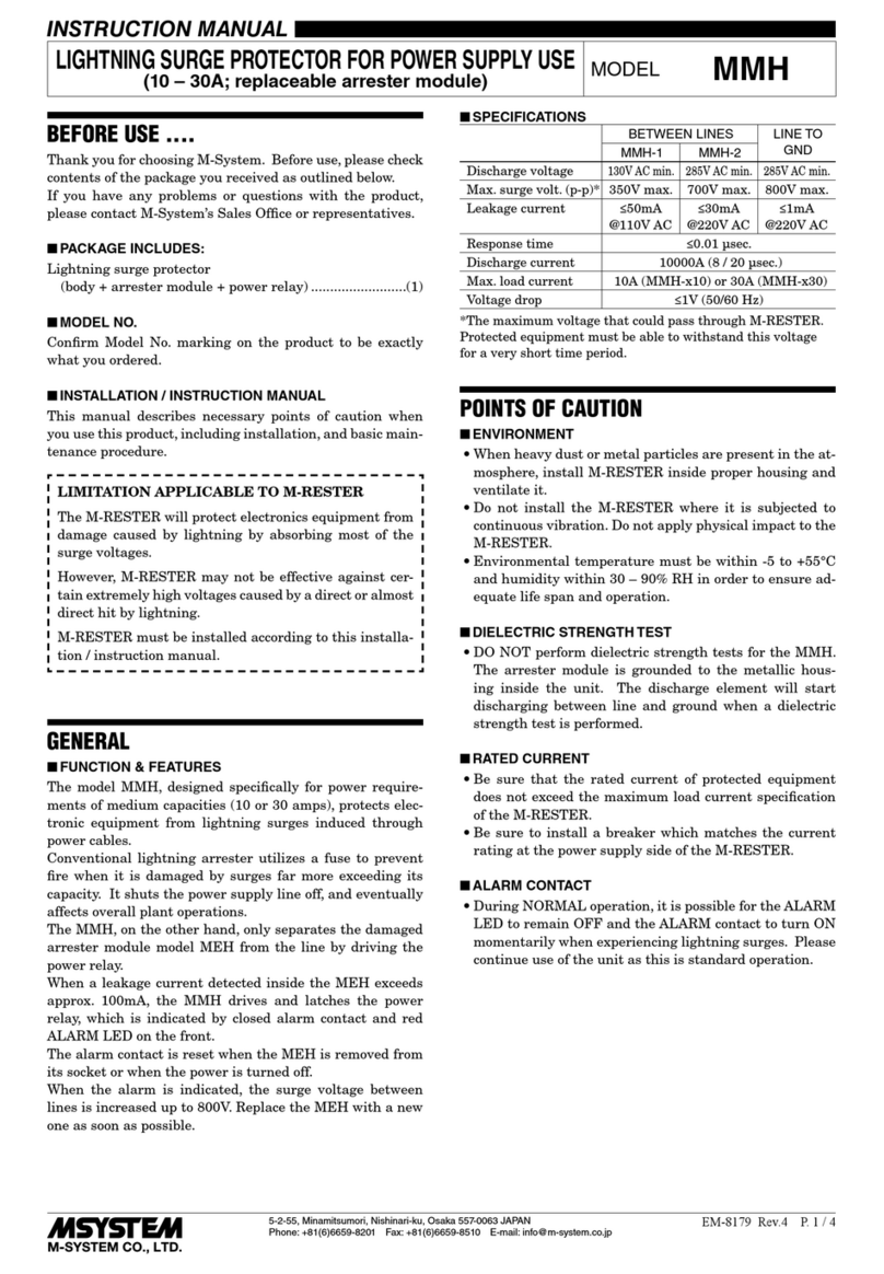
LIMITATION APPLICABLE TO M-RESTER
The M-RESTER will protect electronics equipment from
damage caused by lightning by absorbing most of the
surge voltages.
However, M-RESTER may not be effective against cer-
tain extremely high voltages caused by a direct or almost
direct hit by lightning.
M-RESTER must be installed according to this installa-
tion / instruction manual.
GENERAL
■FUNCTION & FEATURES
•High discharge current capacity 20 kA (8 / 20 µs), 1 kA
(10 / 350 µs)
•Ultra-thin 7-mm-wide module can be mounted in high
density
•Excellent protection employing multi-stage SPD circuits
•DIN rail mounting and grounding
•Shield terminal provided
•Protects strain gauges and transmitters
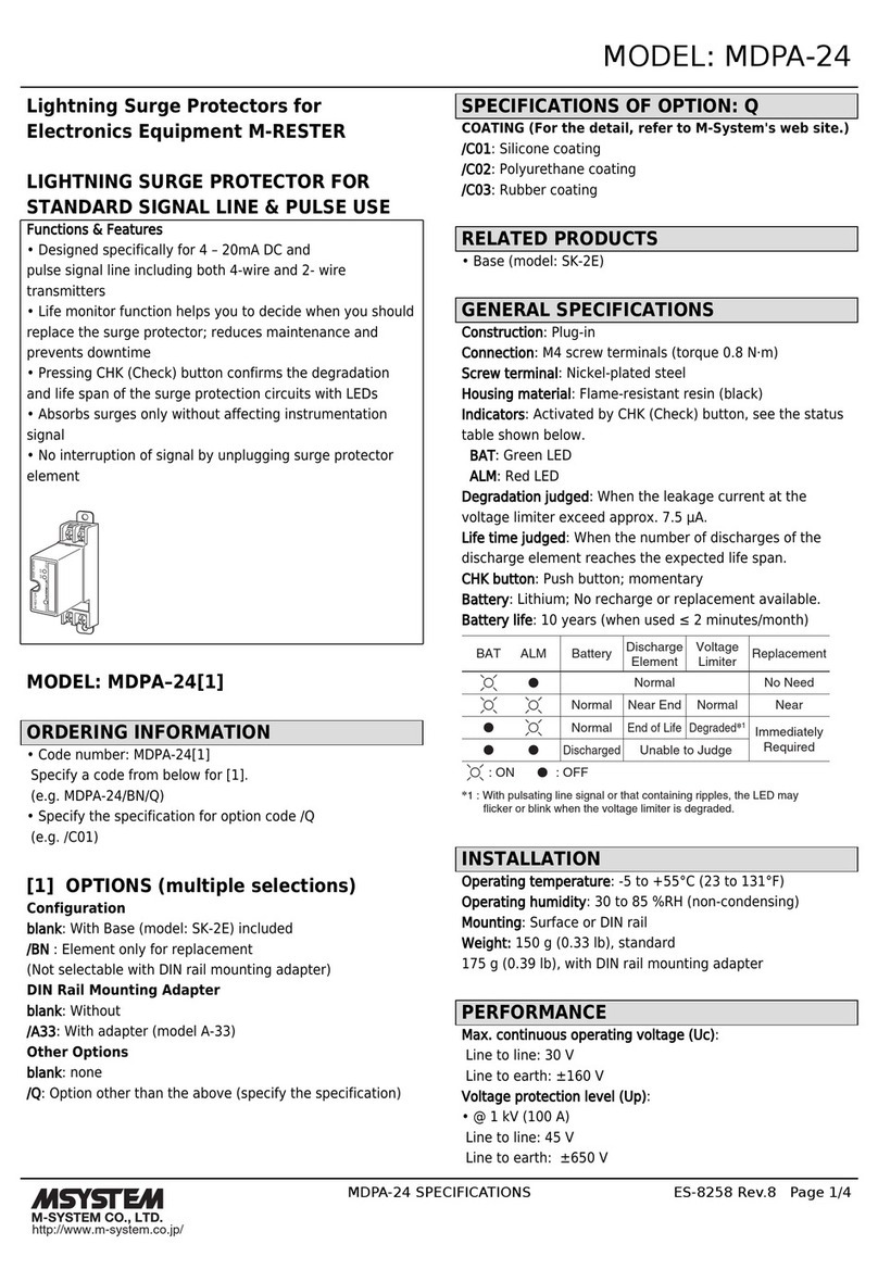
■SPECIFICATIONS
See Table 1.
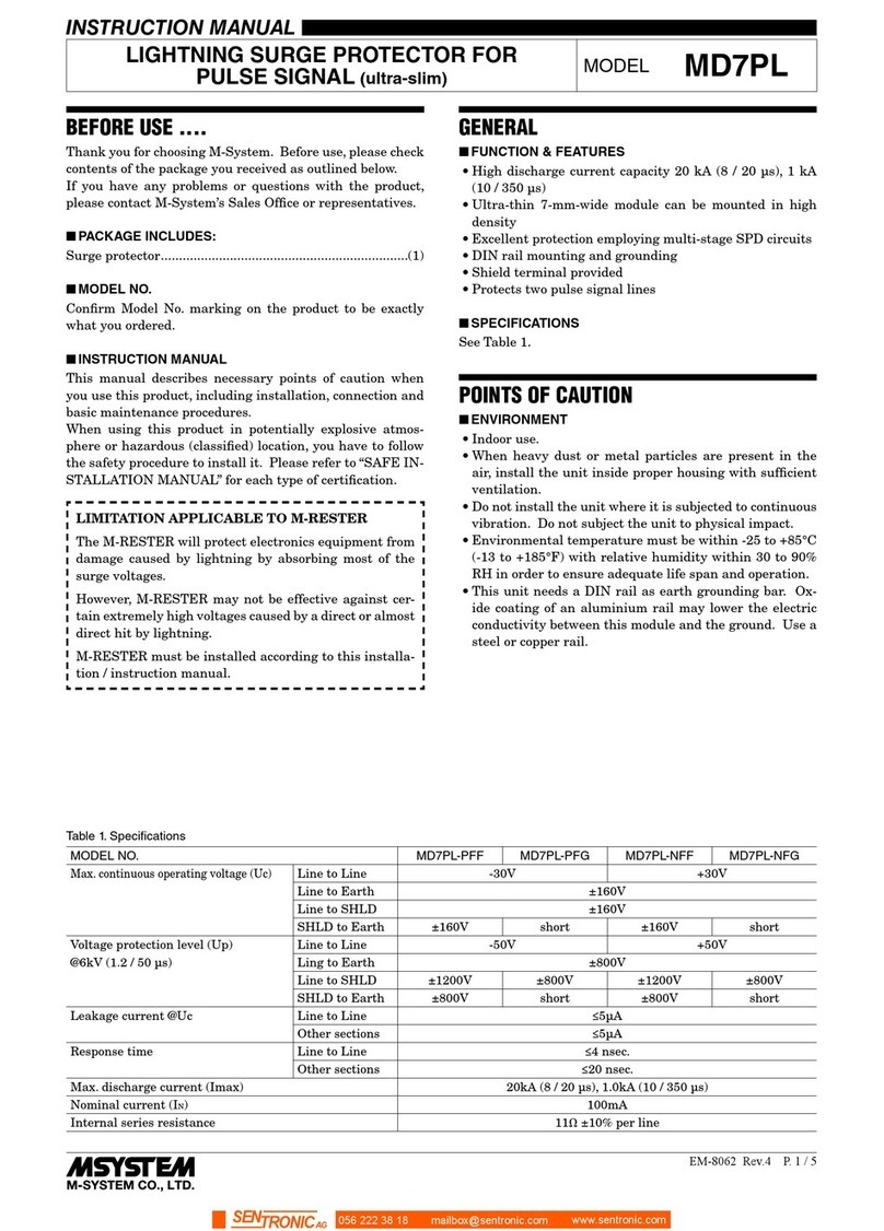
Table 1. Specications
MODEL NO. MD7LC-0 MD7LC-1
Max. continuous operating voltage (Uc)
Output voltage ±0.2V
Excitation 15V
Line to Earth*1±15V
Voltage protection level (Up) Output voltage ±15V @0.2kV (1.2 / 50 µs) ±40V @6kV (1.2 / 50 µs)
Excitation 30V @0.2kV (1.2 / 50 µs) 50V @6kV (1.2 / 50 µs)
Line to Earth*1±30V @0.2kV (1.2 / 50 µs) ±50V @6kV (1.2 / 50 µs)
Leakage current @Uc Output voltage ≤0.2µA
Excitation ≤2µA
Line to Earth*1≤2µA
Response time ≤4 nsec.
Max. discharge current (Imax) 100A (8 / 20 µs)
20kA (8 / 20 µs), 1kA (10 / 350 µs)
Nominal current (IN) ---- 250mA
Internal series resistance ---- 1.5Ω ±10% per line
*1. Measured across the terminal 2 and DIN rail, the terminal 7 and DIN rail.
056 222 38 18 mailbox@sentronic.com www.sentronic.com
SENTRONIC AG
MD7LC
EM-8063 Rev.3 P. 2 / 4
POINTS OF CAUTION
■ENVIRONMENT
•Indoor use.
•When heavy dust or metal particles are present in the
air, install the unit inside proper housing with sufficient
ventilation.
•Do not install the unit where it is subjected to continuous
vibration. Do not subject the unit to physical impact.
•Environmental temperature must be within -25 to +85°C
(-13 to +185°F) with relative humidity within 30 to 90%
RH in order to ensure adequate life span and operation.
•This unit needs a DIN rail as earth grounding bar. Ox-
ide coating of an aluminium rail may lower the electric
conductivity between this module and the ground. Use a
steel or copper rail.
■DIELECTRIC STRENGTH TESTING
•The surge protector starts discharging when a voltage
greater than 15V is applied between lines and earth. Re-
move the grounding wire before conducting a test. Be
sure to return the wire after the test.
■AND ....
•We recommend that you keep spare surge protectors so
that you can replace them when necessary.
•Lightning surge can enter not only through signal lines
but also through power supply lines. We recommend that
you also use the Lightning Surge Protector for Power
Lines for adequate protection.
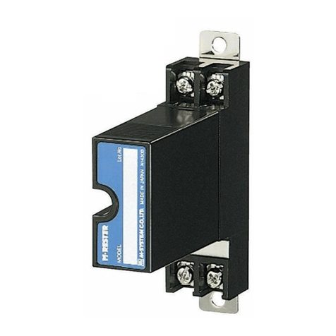
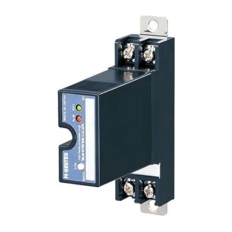
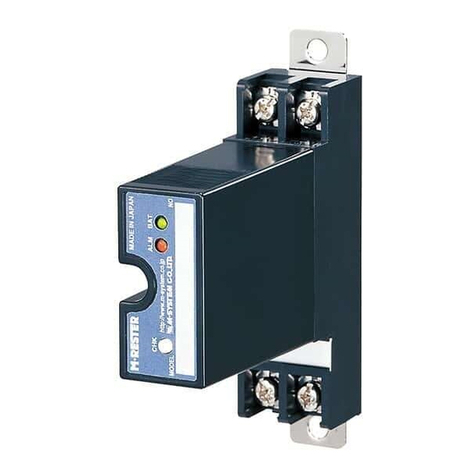
COMPONENT IDENTIFICATION
Body
Spring Loader
DIN Rail Mounting
Adaptor (for grounding)
Connection
Diagram
(left side)
Model No.
Indication
INSTALLATION
Mount the unit on a DIN rail. Once installed, do not move
it to another DIN rail.
■MOUNTING THE UNIT ON A DIN RAIL
A)Hang the upper hook of the DIN rail mounting adaptor at
the rear side of unit, on the DIN rail.
B)Push in the lower in keeping pressing the unit to the DIN
rail.
C)DIN rails generally have slight individual variability in
size. If you find it difficult to push in the lower part, go
back to (A) and hang the upper part more deeply onto the
rail and try (B) again.
A
DIN Rail
B
■REMOVING THE UNIT
A)Push down the spring loader utilizing a minus screwdriv-
er.
B)Confirm that it is pulled enough down and pull out the
lower part of the unit.
C)Detach the upper part from the DIN rail.
A
B
Spring Loader
C
056 222 38 18 mailbox@sentronic.com www.sentronic.com
SENTRONIC AG
MD7LC
EM-8063 Rev.3 P. 3 / 4
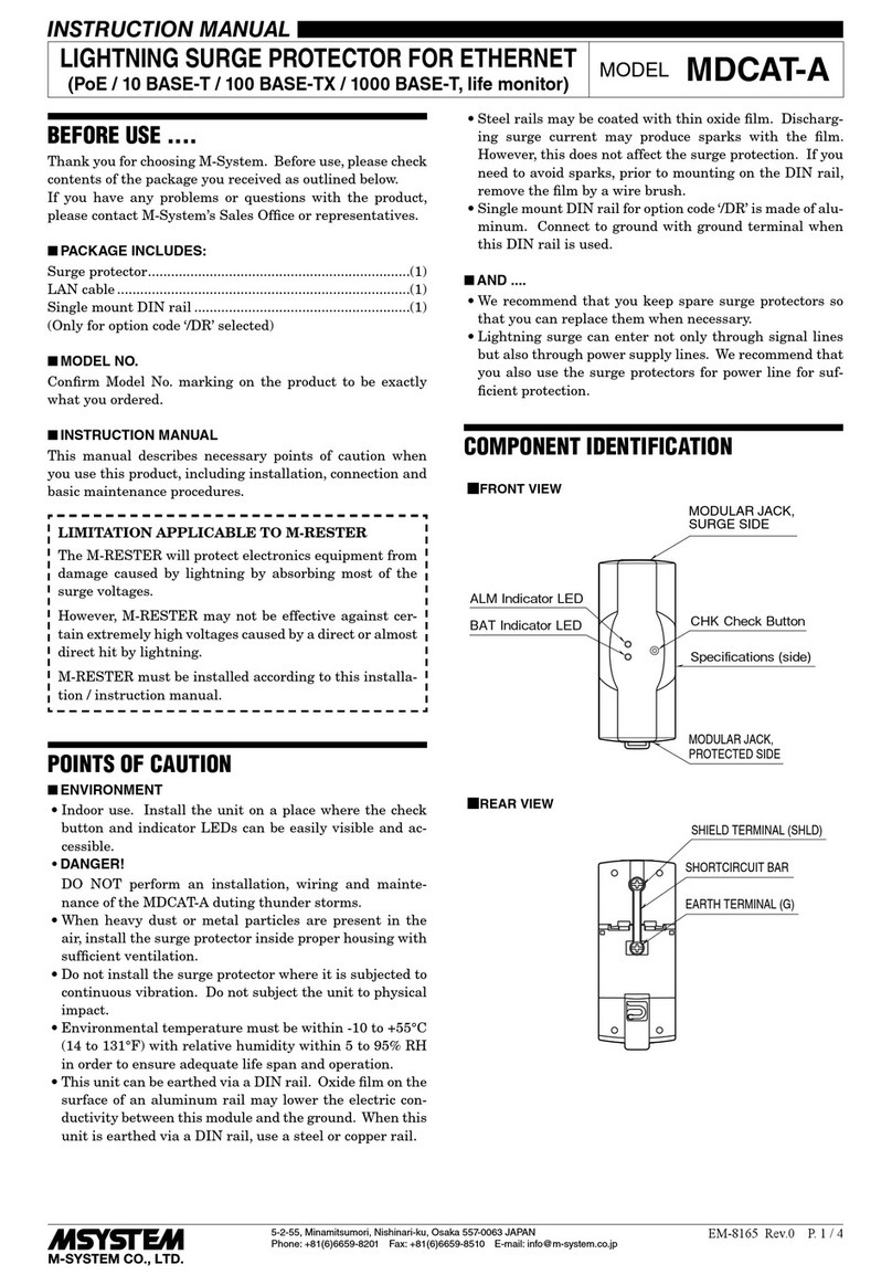
TERMINAL CONNECTION
Connect the unit as in the diagram below.
Be sure to ground the DIN rail on which the unit is mounted and cross-wire between the rail and FG terminal of the protected
device as shown in Figure 1 in order to equalize the earth potential.
When the unit is connected with a device which has no FG terminal, ground the surge protector only.
■EXTERNAL DIMENSIONS unit: mm (inch)
8
6
5
4
1
2
3
7
4
1
5
2
6
3
8
7
95 (3.74)
7
(.28)
98 (3.86) [1.5 (.06)]
8–M3 EURO
TERMINAL
DIN RAIL
(35 mm wide)
DIN RAIL
ADAPTOR
WIRE INSERTION ANGLE: approx. 20°
57 (2.24)
1.9 (.07)
■Figure 1. GROUNDING
M-RESTER PROTECTED
EQUIPMENT
FG
CROSSOVER WIRE
Cross-wire from the DIN rail to the metal housing of the protected device
to equalize the ground potential.
Ground only the surge protector when the protected device has no
grounding terminal.
DIN RAIL ADAPTOR
(for grounding)
DIN RAIL
Grounding
Note: No need of cross wiring for the protected devices connected to the
MD7G.
■CAUTION WHEN WIRING
Hold the module steady at the front when you
tighten/loosen screw terminals.
056 222 38 18 mailbox@sentronic.com www.sentronic.com
SENTRONIC AG
MD7LC
EM-8063 Rev.3 P. 4 / 4
■CONNECTION DIAGRAM
Strain Gauge
Transmitter
(protected device)
G
Strain Gauge
Shield Wire
EXC.
OUTPUT
M-RESTERsurge
side
surge
side
protected
side
protected
side
MD7G
OUTPUT
POWER
EXC.
INPUT
–
+
U
–
+
–
+
G
V
DIN RAIL ADAPTOR
(for grounding)
DIN RAIL
Grounding
DIN RAIL ADAPTOR
(for grounding)
78
MD7G
DIN RAIL ADAPTOR
(for grounding)
87
5 2
6 3
7
8
4 1
M-RESTER
DIN RAIL ADAPTOR
(for grounding)
2 5
3 6
8
7
1 4
*1. Without the MD7G, cross-wire between the DIN rail and the metal housing of the protected device to equalize the earth potential.
*2. Oxide film on the surface of an aluminium rail may lower the electric conductivity between this module and the ground. Use a steel or copper rail.
*3. Be sure to ground the DIN rail. Recommended grounding resistance ≤100Ω.
*2
*3
DIN RAIL
Grounding
*2
*3
*1*1
WIRING INSTRUCTIONS
■EURO TERMINAL
Torque: 0.3 N·m
Applicable wire size: 0.2 – 2.5 mm2
Stripped length: 8 mm
MAINTENANCE
Check surge protectors periodically. Many cases of light-
ning are ignored, and even lightning at a far distance often
causes inductive surges.
We recommend that you check your surge protector about
twice a year, before and after the rainy season. Check
whenever you experience a strong lightning occurrence.
Checking procedure is explained in the following:
■CHECKING
WIRING
1) Make sure that wiring is done as instructed in the con-
nection diagram.
2) Make sure that the DIN rail is connected to the metal
enclosure of protected device.
3) Make sure that the surge protector is securely attached
to the DIN rail, and that the rail is grounded to earth.
■DISCHARGE ELEMENT
1) Remove all wiring connected to the surge protector when
you test the module.
2) Check resistance across the following terminals on the
high resistance range of multimeter (measuring current
≤ 0.25 µA) and confirm no conduction.
Terminals (4) – (5), (6) – (8),
(5) – (DIN rail), (8) – (DIN rail)
The tester should show 1 MΩ or greater for the terminals
(6) – (8), 10 MΩ or greater for other sets of terminals.
When measuring across (4) – (5), connect the tester’s
probe so that the positive voltage is applied to (4).
3) Confirm conduction across the same terminals with a 500
V DC 1000 MΩ insulation tester The tester should show
20 MΩ or less.
4) If any of the above tests shows negative, replace the
surge protector.
056 222 38 18 mailbox@sentronic.com www.sentronic.com
SENTRONIC AG

This manual suits for next models

5

Other M-system Surge Protector manuals
M-system MD74R User manual

M-system

M-system MD74R User manual

M-system MDCAT 5E User manual

M-system

M-system MDCAT 5E User manual

M-system MDPA-24 User manual

M-system

M-system MDPA-24 User manual
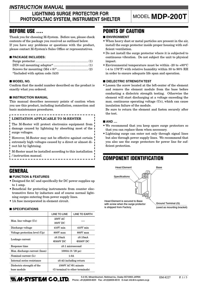
M-system MDP-DM3 User manual

M-system

M-system MDP-DM3 User manual

M-system MD7TC User manual

M-system

M-system MD7TC User manual

M-system MDH User manual

M-system

M-system MDH User manual

M-system MD7ST User manual

M-system

M-system MD7ST User manual

M-system MD7RB-FF User manual

M-system

M-system MD7RB-FF User manual

M-system MDP-24-1 User manual

M-system

M-system MDP-24-1 User manual

M-system MMA User manual

M-system

M-system MMA User manual

M-system MDP-200T User manual

M-system

M-system MDP-200T User manual
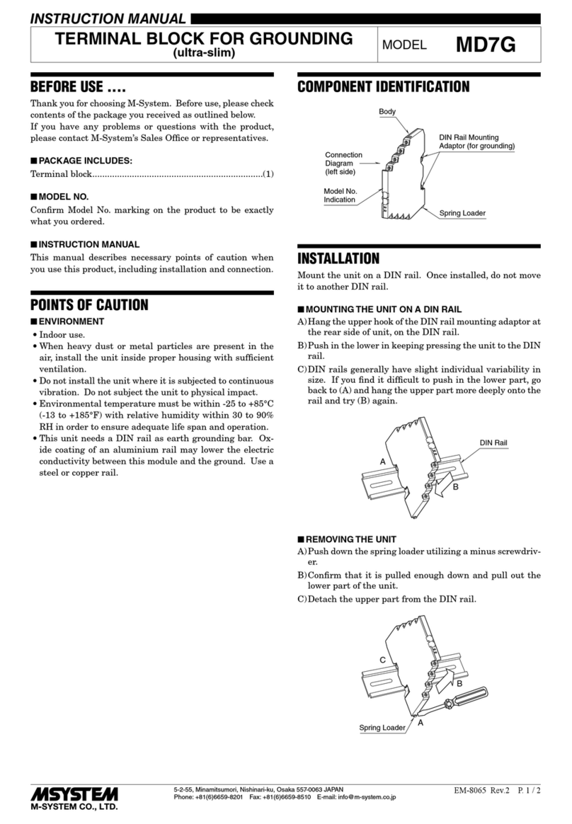
M-system MGA-100 User manual

M-system

M-system MGA-100 User manual

M-system MAL-230x User manual

M-system

M-system MAL-230x User manual

M-system MD6x-24 User manual

M-system

M-system MD6x-24 User manual

M-system MDP-LWA User manual

M-system

M-system MDP-LWA User manual
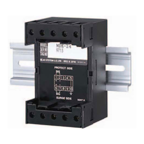
M-system MDK-24 User manual

M-system

M-system MDK-24 User manual

M-system MAT2 Series User manual

M-system

M-system MAT2 Series User manual

M-system MD7LWA User manual

M-system

M-system MD7LWA User manual

M-system MDP-SP User manual

M-system

M-system MDP-SP User manual

M-system MH-1201 User manual

M-system

M-system MH-1201 User manual

M-system MDP-100 User manual

M-system

M-system MDP-100 User manual

M-system MD7PL User manual

M-system

M-system MD7PL User manual

M-system MMAH Series User manual

M-system

M-system MMAH Series User manual

M-system MA-100 User manual

M-system

M-system MA-100 User manual
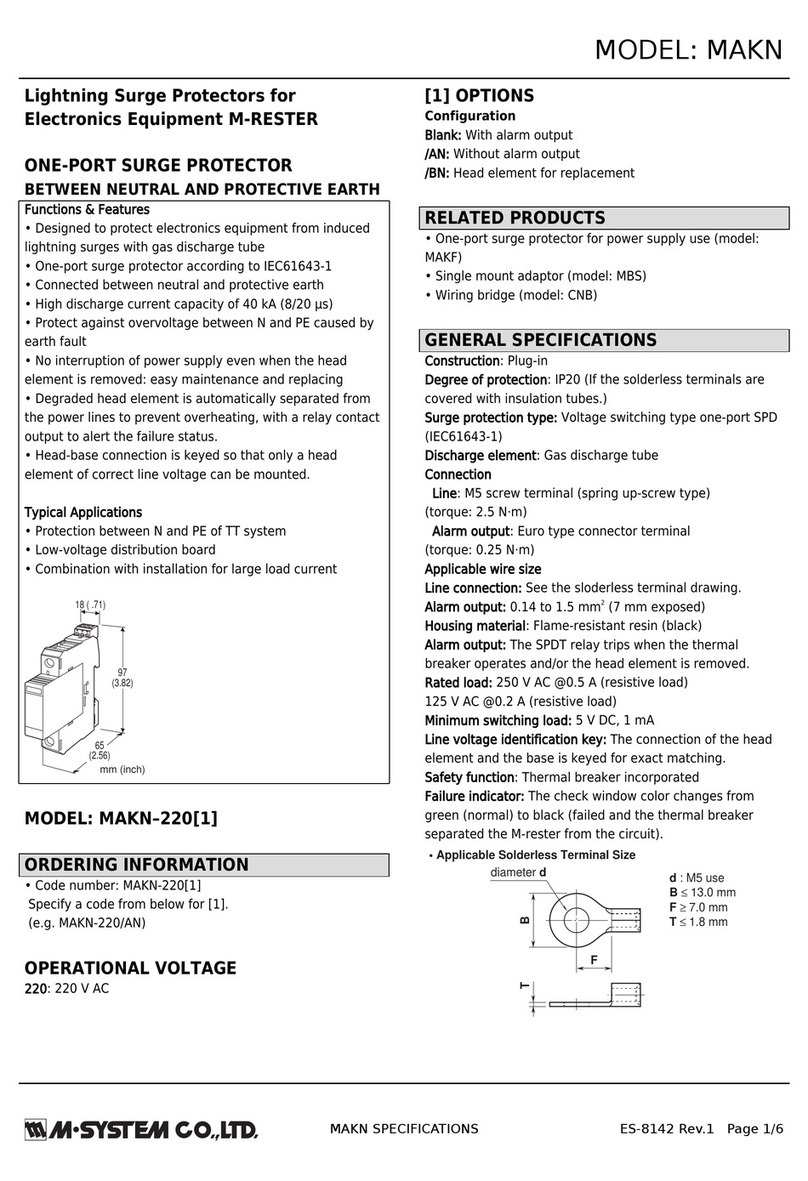
Popular Surge Protector manuals by other brands

Mitsubishi Electric LITOL LTM-125RF manual

Mitsubishi Electric

Mitsubishi Electric LITOL LTM-125RF manual

CyberPower CSHT808TC user manual

CyberPower

CyberPower CSHT808TC user manual

Speco SPTVIVP user manual

Speco

Speco SPTVIVP user manual

CPT PSC3-5 PV installation instructions

CPT

CPT PSC3-5 PV installation instructions

QVS PP114M Specification sheet

QVS

QVS PP114M Specification sheet

Leviton 51020-WMT installation instructions

Leviton

Leviton 51020-WMT installation instructions

Ilsco SSI SpecPRO CSM 32 Series manual

Ilsco

Ilsco SSI SpecPRO CSM 32 Series manual

Philips SPP1182WC Specifications

Philips

Philips SPP1182WC Specifications

Bauhn ASPP8-0723-W user guide

Bauhn

Bauhn ASPP8-0723-W user guide

CyberPower CSB404 user manual

CyberPower

CyberPower CSB404 user manual

Emerson SOLAHD STCPOE65FF quick start guide

Emerson

Emerson SOLAHD STCPOE65FF quick start guide

Panamax MFP-400 instructions

Panamax

Panamax MFP-400 instructions

RCA PS42R Important information

RCA

RCA PS42R Important information

Philips SPN5087E/10 user manual

Philips

Philips SPN5087E/10 user manual

Renkforce 1574788 operating instructions

Renkforce

Renkforce 1574788 operating instructions

Bellodigital ASTU2230 instructions

Bellodigital

Bellodigital ASTU2230 instructions

CyberPower HT705UC user manual

CyberPower

CyberPower HT705UC user manual

Furman M-85 Merit Series owner's manual

Furman

Furman M-85 Merit Series owner's manual

manuals.online logo
manuals.online logoBrands
  • About & Mission
  • Contact us
  • Privacy Policy
  • Terms and Conditions

Copyright 2025 Manuals.Online. All Rights Reserved.