manuals.online logo
Brands
  1. Home
  2. •
  3. Brands
  4. •
  5. Infinity
  6. •
  7. Amplifier
  8. •
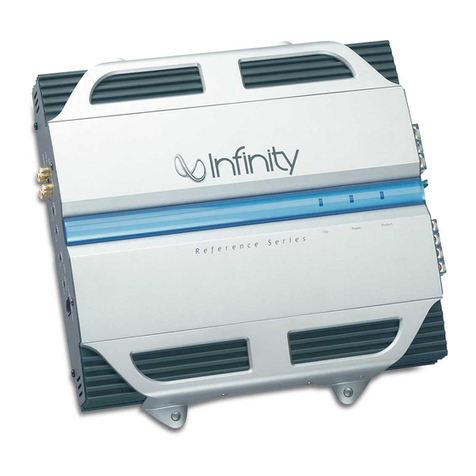
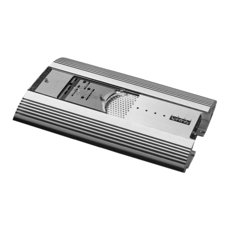
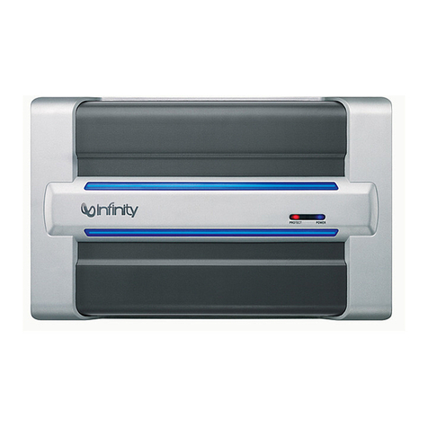
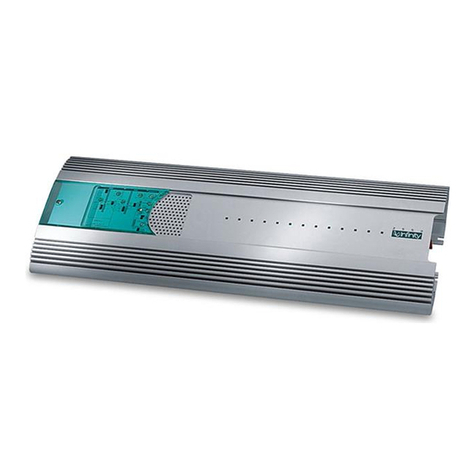
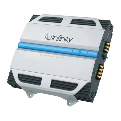
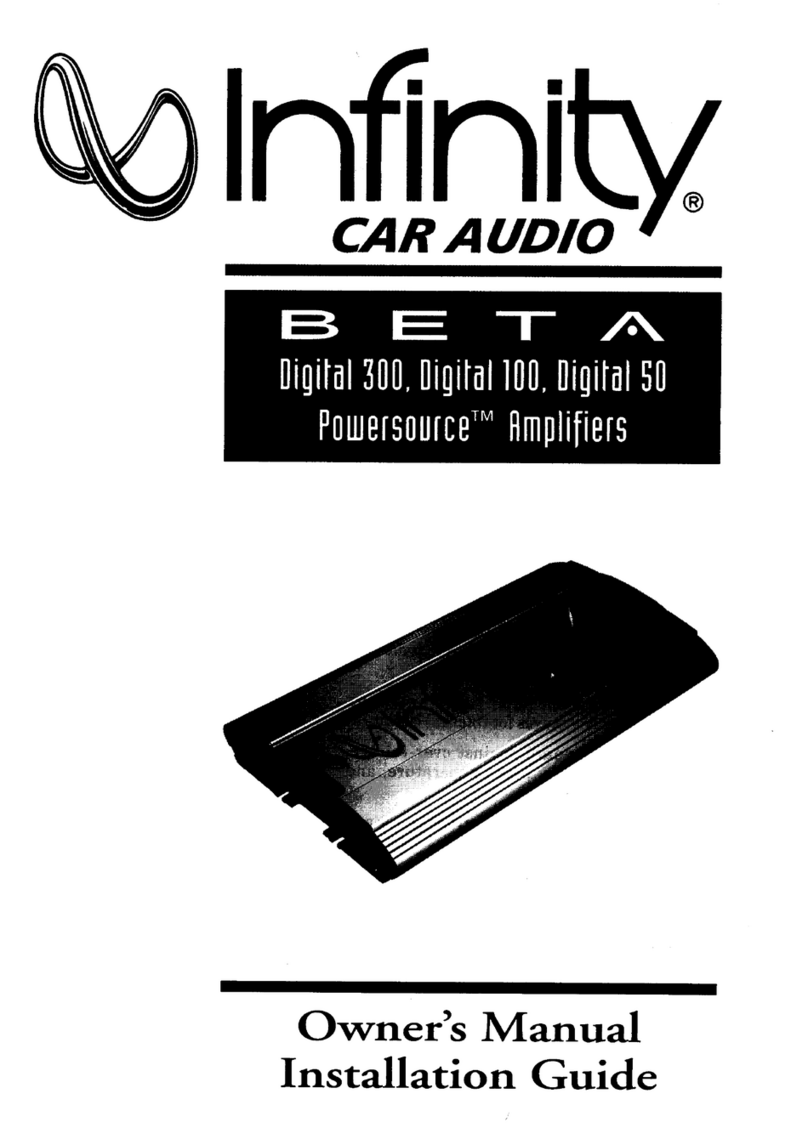
  9. Infinity DPA 275 Programming manual

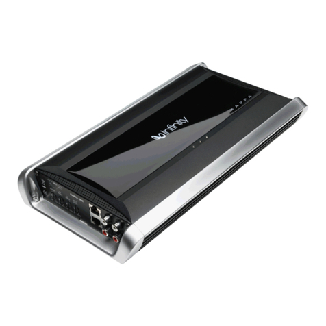
Infinity DPA 275 Programming manual

This manual suits for next models

1

Other Infinity Amplifier manuals

Infinity Kappa 102a User manual

Infinity

Infinity Kappa 102a User manual

Infinity REF-704a User manual

Infinity

Infinity REF-704a User manual

Infinity 310a User manual

Infinity

Infinity 310a User manual

Infinity 1211a User manual

Infinity

Infinity 1211a User manual

Infinity RS KAPPA PS-8 User manual

Infinity

Infinity RS KAPPA PS-8 User manual

Infinity Basslink 4SC User manual

Infinity

Infinity Basslink 4SC User manual

Infinity 611A User manual

Infinity

Infinity 611A User manual

Infinity Kappa 202a User manual

Infinity

Infinity Kappa 202a User manual

Infinity 310a User manual

Infinity

Infinity 310a User manual

Infinity Reference 1300A User manual

Infinity

Infinity Reference 1300A User manual

Infinity 475a User manual

Infinity

Infinity 475a User manual

Infinity K600 User manual

Infinity

Infinity K600 User manual

Infinity reference series User manual

Infinity

Infinity reference series User manual

Infinity 5760a User manual

Infinity

Infinity 5760a User manual

Infinity Basslink 4SC User manual

Infinity

Infinity Basslink 4SC User manual

Infinity kappa series User manual

Infinity

Infinity kappa series User manual

Infinity Kappa 255A User manual

Infinity

Infinity Kappa 255A User manual

Infinity Kappa 54a 4-Ch User manual

Infinity

Infinity Kappa 54a 4-Ch User manual

Infinity KAPPA K2 Programming manual

Infinity

Infinity KAPPA K2 Programming manual

Infinity 7520a User manual

Infinity

Infinity 7520a User manual

Infinity Kappa Center User manual

Infinity

Infinity Kappa Center User manual

Infinity Beta Powersource Digital 300 Programming manual

Infinity

Infinity Beta Powersource Digital 300 Programming manual

Infinity 7521A User manual

Infinity

Infinity 7521A User manual

Infinity Reference 5350A User manual

Infinity

Infinity Reference 5350A User manual

Popular Amplifier manuals by other brands

Magnat Audio EDITION FOUR Owner's manual/warranty document

Magnat Audio

Magnat Audio EDITION FOUR Owner's manual/warranty document

Inter-m PA-2000A Operation manual

Inter-m

Inter-m PA-2000A Operation manual

Yamaha TX6n owner's manual

Yamaha

Yamaha TX6n owner's manual

Peavey TNT 150 user guide

Peavey

Peavey TNT 150 user guide

Bosch LBB 1903/10 Installation and user instructions

Bosch

Bosch LBB 1903/10 Installation and user instructions

Avocent Emerge DA1200D Installer/user guide

Avocent

Avocent Emerge DA1200D Installer/user guide

Redgum RGi35 operating instructions

Redgum

Redgum RGi35 operating instructions

Cambridge Audio AXA25 user manual

Cambridge Audio

Cambridge Audio AXA25 user manual

Alpine MRP-M200 owner's manual

Alpine

Alpine MRP-M200 owner's manual

Technical Pro H1502UrBT user manual

Technical Pro

Technical Pro H1502UrBT user manual

FMS EMGZ307 operating manual

FMS

FMS EMGZ307 operating manual

Racal Instruments 5601 user manual

Racal Instruments

Racal Instruments 5601 user manual

Valcom V-1094A Technical specifications

Valcom

Valcom V-1094A Technical specifications

Cambridge Audio 851D user manual

Cambridge Audio

Cambridge Audio 851D user manual

QSC 3800 Specifications

QSC

QSC 3800 Specifications

NAD C300 owner's manual

NAD

NAD C300 owner's manual

Rotel RMB-1077 owner's manual

Rotel

Rotel RMB-1077 owner's manual

Peavey Monitor 300 Series operating guide

Peavey

Peavey Monitor 300 Series operating guide

manuals.online logo
manuals.online logoBrands
  • About & Mission
  • Contact us
  • Privacy Policy
  • Terms and Conditions

Copyright 2025 Manuals.Online. All Rights Reserved.

Winfini
CAR
AUDIO
DPA
275/250
Digital
&
Power
Amplifier
Owner’s
Manual
Installation
Guide
Owner’s
Manual
and
Installation
Guide
FEATURES...
HPDA
CONVERTERS
HiGH
EFFICIENCY
Introduction
a
se
al
a
a
ar
rm
S
gS
A
NT
INTRODUCTION
The
Infinity
DPA
275/250
Digital
Power
Amplifier
is
a
breakthrough
innovation
for
the
mobile
audio
after-market.
You
now
own
a
digital
amplifier
that
car
audio
enthusiasts
everywhere
have
only
dreamed
of
—
until
now!
The
DPA
275/250
is
the
next
generation
of
amplification,
and
it
makes
all
other
mobile
amplifier
technologies
obsolete.
The
DPA
275
offers
stereo,
bridged-mono,
or
tri-
mode
operation,
and
delivers
75
watts
(rms)
per
channel
into
a
4-ohm
load.
The
DPA
250
produces
50
watts
(rms)
per
channel
operating
in
stereo.
Otherwise,
both
models
come
with
these
features:
¢
Our
innovative
Differential
Amplification
Output
Switching
is
the
design
essence
of
this
product
HPDA
(High
Power
Digital-to-Analog)
Converter
on
each
channel
to
directly
convert
digital
signals
into
amplified
analog
audio
waveforms
*
Custom-Designed
High-Speed
MOSFET
Switching
Power
Supply
to
supply
voltages
for
internal
circuits
Five
protection
levels
guard
against
Over-Voltage,
Under-Voltage,
Over-Power,
Over-Temperature,
and
Over-Current
situations
¢
High
efficiency
~
requires
far
less
electrical
power
and
generates
a
smaller
amount
of
heat
*
Small
footprint
~
when
compared
to
conventional
Class
AB
amplifiers
with
equivalent
power
ratings
¢
Amplifier
input
sensitivity
control
—
to
match
a
wide
range
of
input
signal
levels
The
DPA
275
has
a
bass
equalization
control
to
provide
up
to
11
dB
of
bass
boost
at
40
Hz
Color-keyed,
industrial-grade,
gold-plated
connections
—
easy-to-install
high-quality
interface
e
Connection
cover
~
defeats
tampering
with
installation
wiring
Rugged,
sleek-looking
case
—
built
for
the
road,
yet
is
still
a
showpiece
SOlnfinity
Asout
THIS
MANUAL...
PPA:
207
20:0
This
Infinity
product
is
made
with
our
ongoing
dedication
to
create
the
best
consumer
audio
products
possible.
As
a
result,
you
can
expect
your
DPA
275/250
Digital
Power
Amplifier
to
provide
you
with
many
years
of
listening
enjoyment.
Save
these
instructions
for
future
reference.
All
Infinity
Automotive
Products
carry
a
limited
one-
year
parts
and
labor
warranty,
so
retain
the
bill
of
sale
to
protect
your
purchase
in
the
unlikely
event
of
failure
during
the
warranty
period.
To
attain
maximum
amplifier
performance,
we
encourage
you
to
read
the
remaining
pages
before
installing
and
operating
the
Infinity
DPA
275/250
Digital
Power
Amplifier.
Since
this
product
is
such
a
radical
departure
from
any
other
amplifier
available
today,
we’ve
devoted
the
next
section
to
a
Technical
Overview,
so
you
can
understand
what's
going
on
inside
the
chassis.
TABLE
OF
CONTENTS
TECHNICAL
OVERVIEW....cccccoceccccccccssccseessened
DESIGNING
IT
WASNT
EASY....cccccccccvevcccscscend
HiGH-SPEED
MOSFET
POWER
SUPPLY....ccscsees
NEW
DIGITAL
TECHNOLOGY
..cccccscccccscsccsscceses@
[APPLICATIONS
cccccsssscessesesececcscccseseessereersase®
STEREO:
SYSTEM
cecssaccscecccdsustcienncasvassestessonsc®
BRIDGED-MONO
(DPA
275
ONLY)
.cccccsssseseee
TRI-MODE
(DPA
275
ONLY)....cccsscccorsvesenes
IO
PRECAUTIONS
AND
NOTES.......cccscccsssccssveel
|
INSTALLATION
.....ccssccccccssscccccscccccessscsscccssest
PARTS:
EIST
ccccvscscssccsdcnccsexsaateacastdeasscescccielo
MOUNTING
cocseciscccictsccescescccteecetaccieusaesissclo
WIRING
sessccccaseicsccacévaveuescudanscacensncsccucese
4
SETTING
INPUT
SENsiTIviTY
AND
BAss
EQ......15
INSTALLING
THE
COVER....cccscccscssnescreccsenscceel@
IN
CASE
OF
TROUBLE.
..cosccovscccvccescccssessoeseselO
SPECIFICATIONS
eas
eb
bdeuadceuwaseeaeseneseccaseackeonslh
2
Table
Of
Contents

Owner’s
Manual
and
Installation
Guide
TECHNICAL
OVERVIEW
DESIGNING
IT
Creating
a
digital
car
amplifier
is
no
small
feat.
In
fact,
we've
devoted
the
equivalent
of
over
5000
man-
WASN’T
EASY...
hours
to
developing
and
testing
prototypes
to
come
|
up
with
the
unique
design
used
in
the
Infinity
DPA
Digital
Power
Amplifier.
Along
every
step
of
the
way,
we
gained
insight
about
how
to
solve
major
design
obstacles
—
like
temperature
and
humidity
extremes,
widely-varying
electrical
system
voltages,
complex
load
impedances,
RFI
(radio
frequency
interference)
concerns,
and
a
multitude
of
interface
options.
As
a
result,
we
had
to
develop
several
unique
circuit
topologies
for
the
Infinity
DPA
series
amplifier,
as
shown
in
Figure
1.
rr
i
FET
Switch
35
Vde
Rectifiers
and
-15
Vde
Filters
to
Convert
125
kHz
fo
Fnergy
Storage
Capacitors
and
RF|
Filters
Ground
+10
tat.
5
Vde
(from
battery)
Common
filtered
415
Vde
DC
valtages
+
35
Vdc
FET
Switch
ee
an
Controland
|--------+-----'
Remote
Turr-On
195
Khz
Clock
Over
Voltage
Sensor
ea
Voltage
Sensor
DPA
HIGH-SPEED
ver
Power
Sensor
Over
Temperature
Sensor
MOSFET
SWITCHING
Over
Current
Sensors
POWER
SUPPLY
+35
Vde
(from
Rower
Supply]
High
Power
FET
sui
|
Digital-to-Analog
[HPDA]
>
Converter
Changes
PWM
Pulses
Modulator
Converts
to
Analog
Audio
Audio
Input
Analog
Audio
Voltage
to
Audio
Output
Pulse-Width-Modulated
Digital
Signo!
fone
channel)
aC
[one
channel)
Tg.
=
NN,
-
35
Vde
{from
Power
Supply]
Feedback
DPA
DIGITAL
SWITCHING
AMPLIFICATION
Figure
1.
A
DPA
series
amplifier
contains
a
High-Speed
MOSFET
Sunutching
Power
Supply
and
Digital
Output
Switching
Amplification
technology.
Technical
Overview
EJ
SOInfinity
DPA
2757250
HIGH-SPEED
To
create
the
de
voltages
required
by
the
DPA
275/250’s
internal
circuits,
we
designed
a
new
MOSFET
Power
high-speed
MOSFET
Switching
Power
Supply.
Rather
than
use
off-the-shelf
[Cs
Gintegrated
SUPPLY...
circuits),
we
developed
a
unique
voltage
doubler
circuit
that
has
a
constant
frequency
and
duty
cycle,
with
a
short
signal
path.
This
technique
produces
a
power
supply
with
a
high
90
percent
efficiency
rating,
regardless
of
normal
battery
voltage.
When
combined
with
the
other
circuits,
an
overall
amplifier
efficiency
of
80
percent
is
attained,
measured
as
the
ratio
of
power
out
to
the
speakers
versus
power
from
the
battery.
Why
Is
HiGH
Before
we
go
on,
here’s
why
you
should
be
concerned
about
a
high
efficiency
rating.
Literally,
it
means
a
ErriciENCY
SO
DPA
275/250
amplifier
will
convert
more
of
your
vehicle’s
valuable
electrical
power
into
useful
audio
IMPORTANT?
power,
than
a
Class
AB
analog
amplifier
with
the
same
power
rating.
The
electrical
system
won't
be
strained,
and
much
less
energy
will
be
turned
into
wasted
heat.
Efficiency
100%
90%
DPA
275
8
0%
a
:
|
Se
oan
ee
)
es
~
70%
Operating
Ronge
For
Music
:
See,
one
Reproduction
—
we
ee
50%
i
Me
,
:
conventional
ie
amplifier
40%
al
30%
20%
|
)
20
40
60
80
100
120
140 160
Figure
2.
Efficiency
versus
power
output
for
a
DPA
275
and
a
conventional
analog
car
amplifier
driven
by
a
dc-to-de
converter.
4
|
Technical
Overview
cA
EFFICIENCY
AND
Music
REPRODUCTION
ADVANTAGES
OF
A
HIGHER
Crock
RATE
wner’s
Manual
and
|
tm
a
sha
lavion
Gauide
——_—__=.
Efficiencies
are
typically
measured
at
the
amplifier’s
full
power
rating.
However,
a
close
look
at
a
power
output
versus
efficiency
curve
shows
that
efficiency
varies
directly
as
a
function
of
the
power
output
level.
This
is
more
apparent
when
music
is
the
source,
as
opposed
to
a
sine
wave
test.
Figure
2
(on
the
opposite
page)
shows
measured
efficiencies
versus
power
output
levels
for
a
DPA
275
and
a
conventional
analog
amplifier
driven
by
a
de-
to-de
converter.
|
Notice
that
the
DPA
275
operated
at
over
80
percent
efficiency
over
a
range
of
40
to
80
watts,
resulting
in
very
little
wasted
energy.
In
other
words,
for
every
100
watts
of
battery
power
in,
the
DPA
275
delivered
80
watts
of
music
power
to
the
loudspeaker!
Moreover,
when
music
is
the
source,
an
amplifier
will
operate
at
approximately
one-third
of
its
rated
output
(in
this
case
40
to
80
watts).
This
is
exactly
where
the
DPA
275
(or
DPA
250)
is
most
efficient
during
the
most-used
area
of
operation
—
music
reproduction.
In
the
digital
world,
a
clock
is
a
circuit
which
serves
as
a
single
source
of
pulses
for
use
by
other
circuits,
and
clock
rate
is
the
number
of
pulses
that
occur
per
unit
of
time,
measured
in
Hertz.
The
DPA
275/250
power
supply
uses
a
higher
clock
rate
(125
kHz,
versus
30
kHz
in
typical
designs),
which
presents
several
advantages.
First,
the
size
of
components
and
the
accompanying
package
is
smaller.
This
insures
that
generated
RFI
is
not
audible
and
will
not
interfere
with
the
amplifier’s
switching
frequencies.
In
addition,
a
pair
of
asynchronous
clocks,
controlling
the
switching
circuits
of
the
power
amplifiers,
operate
at
different
frequencies
on
the
left
and
right
channels
to
eliminate
the
possibility
of
any
heterodyne
(1.e.,
radio
beat)
effect.
In
addition,
the
pe
board’s
ground
plane
is
coupled
electrostatically
to
the
chassis,
to
control
virtually
all
RFI
generated
by
the
500
kHz
carrier
(see
page
6).
Five
protection
sensors
monitor
over-voltage,
under-
voltage,
over-power
conditions,
over-temperature
limits,
and
over-current
use.
This
unparalleled
protection
scheme
allows
the
DPA
275/250
to
operate
continually
over
a
range
of
battery
voltages
from
10
to
15.5
V
de
at
all
temperature
extremes.
Technical
Overview
Q9INfiniky
New
DIGITAL
TECHNOLOGY...
INCORPORATES
HPDA
Converters
DPA.
2757750
To
amplify
audio,
we
developed
a
new
technology
called
Differential
Amplification
Output
Switching.
As
shown
in
Figure
1
(on
page
3),
it
consists
of
a
proprietary
500
kHz
pulse-width
modulation
circuit,
to
sample
and
convert
incoming
analog
audio
to
digital
“1-bit”
pulses
(which
is
the
equivalent
of
an
11-times
oversampling
rate
in
digital
audio
terms).
The
high
modulation
frequency
insures
precision
sampling
that
is
free
of
audible
RFI
artifacts,
and
also
allows
us
to
use
passive,
gentle-slope
filtering
—
for
minimum
phase
shift
when
the
analog
waveform
is
reconstructed
at
the
output.
In
essence,
we
have
incorporated
a
High
Power
D-to-A
(HPDA)
converter
within
the
design.
The
digital
pulses
control
a
complementary
pair
of
fast,
high-current
MOSFET
switches
that
create
amplified
70
V
de
pulses
across
the
voltage
rails.
Two-stage
RFI
filtering
removes
the
500
kHz
carrier
frequency,
and
the
result
is
a
pure
amplified
analog
signal
that
is
transparent
and
adds
no
sound
of
its
own!
To
better
understand
how
an
analog
signal
is
extracted
from
a
digital
pulse-width
waveform,
refer
to
Figure
3
during
the
following
discussion.
50
%
duty
analog
PYM
duty
cycle
audio
/
se
7
ae.
signal
/
son
:
i
il
I.
Figure
3.
Duty
cycle
ts
a
measurement
of
the
time
a
digital
signal
is
on
versus
the
time
it
is
off
over
one
cycle
of
the
waveform.
It
is
expressed
as
a
percentage
(e.g.,
a
50
%
duty
cycle
means
the
signal
is
on
half
of
the
time).
A
positive
voltage
increase
in
the
analog
audio
signal
translates
to
an
increased
duty
cycle
in
the
pulse-width
modulated
(PWM)
digital
signal.
RB
echnical
Overview
———
ee...
+
re
Owner’s
Manual
and
Installation
Guide
pay
HPDA
CONVERTERS
AmpPLIFY
AND
RECONSTRUCT
THE
ANALOG
SIGNAL
A
Worp
Asout
LOAD
IMPEDANCES
Figure
4,
Frequency
response
for
a
DPA
275
with
both
channels
driving
loads
of
2,
4,
and
8
ohms.
Note
the
differences
in
the
high
frequencies
when
compared
to
the
optimum
4-ohm.
response.
When
there
is
no
incoming
audio
signal,
the
modulator
circuit
creates
a
pulse-width
waveform
having
a
50
%
duty
cycle.
This
means
the
waveform
—
spends
half
of
its
time
at
+35
V
de
and
the
other
half
of
its
time
at
-35
V
dc.
When
you
sum
(i.e.,
average)
the
areas
under
each
positive
and
negative
excursion
(in
the
way
our
HPDA
does),
you
get
a
net
result
of
zero
—
or
no
voltage
output.
Let’s
assume
an
instantaneous
positive
voltage
is
now
present
at
the
analog
input,
and
the
modulator
shifts
the
duty
cycle
of
the
pulse-width
waveform,
so
more
time
is
spent
at
+35
V
de
than
at
the
-35
V
dc
rail.
When
these
areas
are
averaged,
a
positive
value
at
the
output
is
the
net
result.
Repeating
this
process
creates
a
continuous
amplified
analog
waveform
from
the
stream
of
500
kHz
samples.
For
optimum
performance,
the
DPA
275/250
should
only
drive
a
4-ohm
load.
As
in
crossover
filter
design,
there
is
a
direct
result
of
having
to
specify
a
load
impedance
in
order
to
build
the
output
filters
used
in
the
HPDA
converter.
We
choose
4
ohms
as
the
best
compromise
between
the
most
common
values
of
8
and
2
ohms. Other
loads
can
be
used,
but
they
will
change
filter
characteristics
and
affect
the
amplifier’s
frequency
response,
as
shown
in
Figure
4.
With
an
8-ohm
load,
the
DPA
275/250
response
rises
in
the
high
frequencies
to
produce
a
brighter
sound.
Conversely,
with
a
2-ohm
load,
the
high
frequency
response
rolls
off
faster
for
a
duller
sound.
In
addition,
protection
circuits
will
activate
sooner
to
safeguard
the
amplifier.
Level
{dB}
Frequency
(Hz)
Technical
Overview
7
ROinfinity
DPA
275/250
APPLICATIONS
For
your
convenience,
we've
included
several
application
diagrams
to
help
you
plan
your
own
installation.
Figures
5
through
7
show
how
to
configure
the
DPA
275
for
stereo,
bridged-mono,
or
tri-mode
operation.
For
the
DPA
250,
only
Figure
5
will
apply.
Figure
5.
Wiring
diagrams
for
stereo
operation
of
DPA
275
and
DPA
250
amplifiers.
When
hooked-up
as
shown,
amplifier
outputs
are
in
phase.
DPA
275
Amplifier
Stereo
Mode
L
speaker
R
speaker
DPA
250
Amplifier
Stereo
Mode
L
speaker
R
speaker
a
oo
ae
8
Applications
Owner's
Manual
and
Installation
Guide
me
ne
Figure
6.
Wiring
diagram
for
operating
the
DPA
275
amplifier
in
a
bridged-mono
configuration.
In
this
mode,
only
the
right
channel’s
RCA
input
|
DPA
2
/9
jack
is
active.
i
Am
ol
itier
Mono
Mode
subwoofer
-
Applications
aA