Infinity Reference 1600A User manual

Reference Series
1600a
1 CHANNEL POWER AMPLIFIER
SERVICE MANUAL
Infinity Systems, Inc.
250 Crossways Park Dr.
Woodbury, New York 11797 Rev1 3/2008
Released 2007
Discontinued XXXX

- CONTENTS -
BASIC SPECIFICATIONS ………………..……….……..1
DETAILED SPECIFICATIONS ………….…..…….……..2
PACKING……………………….……………..……………3
APPLICATIONS……………………………………………4
INSTALLATION/SETUP…………………………...…...…5
BASIC TROUBLESHOOTING..…….…….………………5
EXPLODED VIEW/PARTS LIST………………………....6
NOTE ON TOP COVER..…….………………………..….7
AMPLIFIER BLOCK DIAGRAM……………………..……8
P.C.B. DRAWINGS….………………………………..……9
ELECTRICAL PARTS LIST ……………………………. 18
IC/TRANSISTOR PINOUTS..…………………………….23
SCHEMATICS……………….……..…………..……..…..26
Reference 1600a Basic Specifications
Output Power: 400W RMS x 1 @ 4 ohms; ≤1% THD + N
(14.4 VDC) 600W RMS x 1 @ 2 ohms; ≤1% THD + N
Signal-to-noise ratio: 80dBA (reference 1W into 4 ohms)
Dynamic power: 894W channels @ 2 ohms
Effective damping factor: 6.3 @ 4 ohms
Frequency response: 11Hz – 330Hz (-3dB)
Maximum input signal: 6.0V
Maximum sensitivity: 100mV
Output regulation: .12dB @ 4 ohms
Dimensions (L x W x D): 14-3/16" x 9" x 2-11/16" (361mm x 229mm x 69mm)
Fuse: 3 x 25A
Infinity continually strives to update and improve existing products, as well as create new ones. The specifications
and details in this and related JBL publications are therefore subject to change without notice.
1600a Reference Series
1

INFINITY REFERENCE 1600a AMPLIFIER SPECIFICATIONS
TEST VOLTAGE 14.4 +0.1V
Specification Rating Unit Remarks
Power Output 4ohm loads @50Hz ≥400W x 1 Watts
(stereo mode) for each ch @<1.0%THD
(Unit:W)(LPF=22K)
Power Output 2ohm loads @50Hz ≥600W x 1 Watts
(stereo mode) for each ch @<1.0%THD
(Unit:W)(LPF=22K)
THD Power 4 ohm loads
and 1MD@Reference (Unit:%) LPF=22K
≤0.1% @ 50Hz %
THD Power 2 ohm loads
and 1MD@Reference (Unit:%) LPF=22K
≤0.1% @ 50Hz %
Full rated power Distortion 1KHz LPF=22KHz ≤0.1% %
Signal/Noise Ratio
a: 1 watt into 4 ohms
b: full rated power (dB)
80
>105
dBA
1 watt into 4 ohms
1V signal input
Input Sensitivity
Low Level Input( v) @:full rated power 100mV-6V Volts ±20%
Frequency response (Unit:-3dB) 11Hz~330Hz Hz -3dB
Bass Boost:(Unit:dB) @45HZ (±5Hz ) 0~6dB dB ±1dB
Idle Current ( @ 2ohm) 1.2A A ±0.15A
MAX current : rated power
(All channel 2 ohm loads) ≤58A A
DC Offset: ≤30mV mV
Damping Factor (4ohm): >200
Effective damping factor (4ohm): 6.364
Dynamic Power @ 2 ohms 894W Watts
Output Regulation @ 4 ohms 0.12dB dB
Remote Operating Voltages: 5V OFF 3.5V Volts ±1V
Turn on delay time 2 to 3 Sec
Circuit Protection
a. Temperature
b. Speaker Short Circuit
c. Operating Voltage Range
80 ±5 deg C
Yes
8~16V
Dimensions (L x W x H): 14-3/16" x 9" x 2-11/16"
(361mm x 229mm x69mm)
Inches
mm
Fuses 25A x 3 A
1600a Reference Series
2

Item Part Number Description Qty
1 CH4482901202 Outer Carton 1
2 REF1600a REF1600a Amplifier 1
3 Plastic Bag 1
4 BZL279112001 Packing Foam 1
5 Visit Infinitysystems.com Owner's manual 1
6 Plastic Bag 1
7 Accessory kit consisting of: 1
LS1CJ0402507 Mounting Screws 4
1601-253G-00 SPARE 25A FUSES 3
REMOTE REF AMP Remote Level Control 1
2100-0009-04 (RJ11) control cable 1
1600a Reference Series
PACKAGING
3

3
The Reference subwoofer amplifiers are
single-channel amplifiers. There are two sets of
terminals to make it easy to connect multiple
woofers. Either set of (+/–) terminals may be
used when connecting woofers.
To the right are four application diagrams to help
plan your subwoofer system installation.
NOTE: For simplicity, Figures 3 and 4 do not
show power, remote and input connections.
Subwoofers or voice coils connected in series.
Subwoofers or voice coils connected in parallel.
APPLICATIONS – 1300a AND 1600a
Figure 3. Reference 1300a or 1600a amplifier with two
woofer connections.
NOTE: Minimum impedance of each subwoofer = 4 ohms if
subwoofers are connected in parallel and 1 ohm if they
are connected in series.
NOTE: Minimum impedance of subwoofer = 2 ohms
Figure 4. Reference 1300a or 1600a amplifier with one
woofer connection.
1600a Reference Series
4

SETTING INPUT SENSITIVITY
1. Initially turn the INPUT LEVEL control(s) to
the minimum (counterclockwise) position.
2. On the source unit, increase the volume
control to 3/4 volume. Slowly increase the
INPUT LEVEL control(s) toward three o’clock
until you hear slight distortion in the music.
Then reduce the INPUT LEVEL slightly until
distortion is no longer heard.
NOTE: After the source unit is on, blue LEDs (on
the top panel) will light, indicating the amplifier
is on. If not, check the wiring, especially the
remote connection from the source unit. Also
refer to “Troubleshooting.”
REMOTE LEVEL CONTROL
The 1300a, 1600a and 5350a include a remote
level control. This will allow the subwoofer level
to be adjusted from the listening position.
Connect the remote level control using the
RJ11 jack on the side of the amplifier. Install
the control module in the front of the vehicle
within easy reach of the driver. Both the under-
side of the dash and the center console are
suitable locations.
UNDER-DASH MOUNTING
Select a mounting location that allows easy
access to the control while driving. Using the
REMOTE LEVEL control as a template, mark and
drill holes in the mounting surface. Attach the
REMOTE LEVEL control using the mounting
screws provided (Figure 11).
Figure 11. Under-dash mounting of the
REMOTE LEVEL control.
Refer to the illustrations on the previous pages
for control location.
Reconnect the (–) negative lead to the vehicle’s
battery. Apply power to the audio system and
play a dynamic music track.
SETTING THE CROSSOVER(S)
Determine your system plans and set the
crossover-mode switch accordingly. If your
system design does not include a subwoofer,
set the crossover mode to FULL and skip to
“Setting Input Sensitivity.”
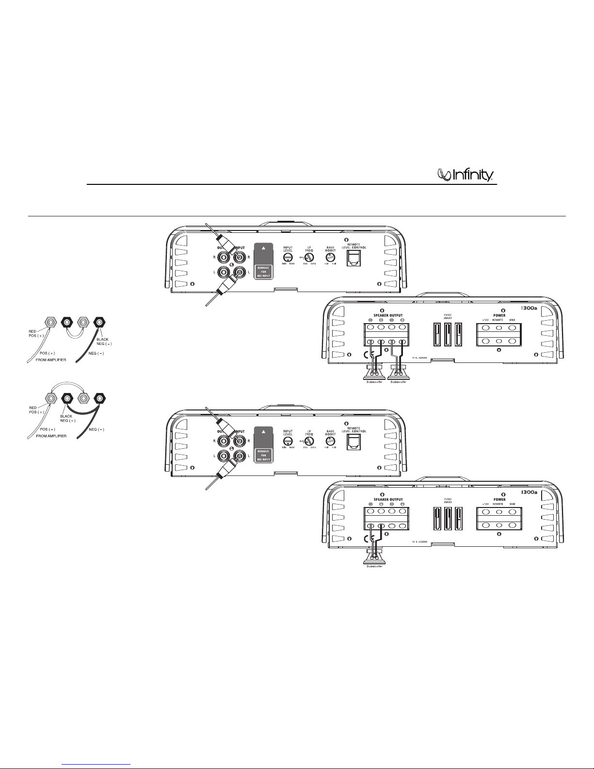
If your system includes a subwoofer, set the
crossover mode to HP (high-pass) for your
full-range speakers. Adjust the crossover
frequency to limit bass, and provide increased
system volume with less distortion.
Mode Switch:
Full: Allows a full-range signal through to the
speakers; can be used with larger full-range
speakers such as 6" x 9"s.
HP: Allows a high-pass signal through to
the speakers; should be used with most
loudspeakers (can protect your full-range
speakers from being overdriven with low
frequencies, one cause of speaker damage).
LP: Allows only bass to pass through to the
speakers; should be selected when powering
subwoofers.
High-Pass Filters: Initially set the crossover-
frequency control midway. While listening
to music, adjust the crossover for the least
perceived distortion from the speakers, allowing
them to reproduce as much bass as possible.
Low-Pass Filters: For subwoofers, choose
the highest frequency that removes vocal
information from the sound of the subwoofer.
If using the 475a to drive a subwoofer(s), set
the crossover mode to LP (low-pass) on the
channels connected to the subwoofer.
NOTE: The 1300a, 1600a and the subwoofer
output of the 5350a are low-pass only and
do not have a crossover-mode switch.
INSTALLATION AND SETUP
Route the cable behind the dash or other
interior panels and under the carpet. Do not
route the cable outside the vehicle. Connect the
RJ11 cable between the RJ11 receptacle on the
amp and the receptacle on the REMOTE LEVEL
control (Figure 12).
Figure 12. REMOTE LEVEL control electrical
connection.
SETTING THE BASS BOOST
The Bass Boost control will allow you to enhance
the bass output of your system at 50Hz up to 6dB.
AUX OUTPUT
Reference amplifiers (except 5350a) are
equipped with full-range outputs that can be
used to connect additional amplifiers.
STATUS LEDs
Power: Indicates the amplifier is on.
Protection: Refer to “Troubleshooting” for specific
indications.
Figure 13. LED status.
TROUBLESHOOTING
• PROBLEM: No audio (POWER LED is off).
CAUSE and SOLUTION: No voltage at BATT+
and/or REM terminals, or bad or no ground
connection. Check voltages at amplifier
terminals with VOM.
• PROBLEM: No audio (PROTECT LED glows red).
CAUSE and SOLUTION: DC voltage on amplifier
output. Amplifier may need service; see
enclosed warranty card for service information.
• PROBLEM: No audio (PROTECT LED glows red).
CAUSE and SOLUTION: Amplifier is overheated.
Make sure amplifier cooling is not blocked at
mounting location; verify that speaker-system
impedance is within specified limits.
• PROBLEM:
No audio (PROTECT LED glows red).
CAUSE and SOLUTION: Voltage less than 9V on
BATT+ connection. Check vehicle charging system.
• PROBLEM: No audio (PROTECT LED glows red).
CAUSE and SOLUTION: Voltage greater than
16V or less than 8.5V on BATT+ connection.
Check vehicle charging system.
• PROBLEM: Distorted audio.
CAUSE and SOLUTION: Input sensitivity is
not set properly, or amplifier or source unit is
defective. Check INPUT LEVEL setting, or check
speaker wires for shorts or grounds.
•PROBLEM: Distorted audio (PROTECT LED glows
intermittently).
CAUSE and SOLUTION: Short circuit in speaker
or wire. Remove speaker leads one at a time to
locate shorted speaker or wire, then repair.
•PROBLEM: Music lacks “punch.”
CAUSE and SOLUTION: Speakers are not
connected properly. Check speaker connections
for proper polarity.
1600a Reference Series
5

Item# Part Number Description Qty
1 SG-0016-2601 Top cover 1
2 GD-600011400 Light panel 1
3 LSIFM0300011 Screw 5
4 SR-1300-0117 Main heat sink 1
5 Main PCB 1
6 MK-0004-2601 Front panel 1
7 LS5KP0300807 Screw for F/RP 8
8 LS5KJ0301007 Screw for terminal, RCA jacks 3
9 XN-10500-012 Knob 3
10 LSIAP0300607 Screw 6
11 LSIAM0300607 Screw 2
12 XG-0017-2601 Bottom plate 1
13 PL-L0007-000 Transistor spring clip (2) 1
14 PL-L0006-000 Transistor spring clip (1) 10
15 LSIAY0301201 Screw 4
16 ZL-10037A-15 Space Pole 4
17 HG-0005-2601 Rear panel 1
18 1601-253E-00 Fuse 25A ATC 3
19 LSIAA0200501 Screw 1
20 LS1AM0250401 Screw 4
21 CP-B00011400 LED lens 1
22 LED PCB 1
1600a Reference Series
6

NOTE ON TOP COVER FOR INFINITY REFERENCE MODELS REF475A, REF1300A, REF1600A
•There was a revision in the top cover design starting with the serial number range(s) noted below, or
identified by the brace design in the supplied images.
•Note the Rev1 Top cover will not fit properly on the original heatsink.
Top Cover Part Numbers
MODEL PART NUMBER SERIAL NUMBER
REF475A SG-0016-2601 EV0001-01000
to
EV0001-09138
REF475A SG-0001-2607 EV0001-09139
And above
REF1300A SG-0016-2601 EV0003-01000
to
EV0003-08606
REF1300A SG-0001-2607 EV0003-08607
And above
REF1600A SG-0016-2601 EV0004-01000
to
EV0004-11811
REF1600A SG-0001-2607 EV0004-11812
And above
1600a Reference Series
7

123456
A
B
C
D
6
54321
D
C
B
A
1
2
INPUT L
1
2
OUTPUT L
INPUT R
OUTPUT R
32 320Hz80 32 320Hz50
IMS INPUT
OP
OP
OP
OP
OP
OP AMP
BALANCED
INPUT UNIT
BALANCED
INPUT UNIT
GAIN CONTROL
LP FREQ
VARIABLE
32Hz-320Hz/12dB
BASSBOOST
VARIABLE
0dB-6dB/50Hz MAIN AMP
SPEAKER
2 ohm/4 ohm
2 ohm/4 ohm
Block Diagram REF1600
1600a Reference Series
8

1600a Reference Series
9

1600a Reference Series
10

1600a Reference Series
11

1600a Reference Series
12

1600a Reference Series
13

1600a Reference Series
14

1600a Reference Series
15

1600a Reference Series
16

1600a Reference Series
17

REFERENCE 1600a Electrical Parts List
Part Number Qty Reference Designato
r
MAIN BOARD
Resistors
0702-0106-03 Resistor 10mΩ±1% manganin resistor 1.5 0.5MM
16.5MM 3 R127 R126 R124
0701-2000-02 Resistor SMD 0Ω1/8W ±5% 0805 2 R52 R51
0702-4103-02 Carbon resistor 1W 10KΩ±5% TR 15MM 1 R69
0701-2100-02 Resistor SMD 10Ω1/8W ±5% 0805 6 R111 R112 R110 R109 R108 R10
7
0701-2101-02 Resistor SMD 100Ω1/8W ±5% 0805 23
R165 R164 R163 R162 R161 R160 R159
R144 R128 R125 R101 R90 R89 R86 R74
R47
0701-2221-02 Resistor SMD 220Ω±1/8W 5% 0805 3 R60 R170 R6
5
0701-2102-02 Resistor SMD 1KΩ1/8W ±5% 0805 7 R18 R151 R152 R91 R54 R53 R1
0
0701-2202-02 Resistor SMD R0805 2KΩ1/8W ±5% TR 1 R146
0701-2222-02 Resistor SMD 2.2KΩ1/8W ±5% 0805 7 R197 R185 R140 R135 R134 R157 R15
8
0701-2472-02 Resistor SMD 4.7KΩ1/8W ±5% 0805 3 R32 R39 R87
0701-2512-02 Resistor SMD 5.1KΩ1/8W ±5% 0805 4 R38 R200 R82 R81
0701-2562-02 Resistor SMD 5.6KΩ1/8W ±5% 0805 2 R147 R85
0701-2103-02 Resistor SMD 10KΩ1/8W ±5% 0805 9 R76
0701-2153-02 Resistor SMD 15KΩ1/8W ±5% 0805 1 R70
0701-2203-02 Resistor SMD R0805 20KΩ1/8W ±5% TR 5 R1 R8 R17 R184 R10
4
0701-2223-02 Resistor SMD 22KΩ1/8W ±5% 0805 2 R5 R4
0701-2333-02 Resistor SMD 33KΩ1/8W ±5% 0805 1 R98
0701-2473-02 Resistor SMD 47KΩ1/8W ±5% 0805 22
R181 R180 R97 R92 R26 R25 R14 R23 R15
R11 R9 R13 R77 R68 R6 R7 R75 R24 R195
R194 R196 R71
0701-2563-02 Resistor SMD 56KΩ1/8W ±5% 0805 1 R95
0701-2104-02 Resistor SMD 100KΩ1/8W ±5% 0805 5 R63 R62 R84 R83 R96
0701-2154-02 Resistor SMD 150KΩ1/8W ±5% 0805 2 R94 R93
0702-3220-02 Carbon resistor 1/2W 22Ω±5% TR 12.5MM 3 R169 R168 R16
7
0702-4682-02 Carbon resistor 1W 6.8K ±5% 15mm 2 R176 R177
0702-4123-02 Carbon resistor 1W 12K ±5% 15mm 1 R120
0712-64R7-02 Metalfilm resistor 2W 4.7Ω±5% 10MM 1 R139
0702-6221-02 Carbon resistor 2W 220Ω±5% TR 17.5MM 1 R136
0705-5470-02 Resistor 5W 47Ω±5% 1 R142
0701-2204-02 Resistor SMD 200KΩ1/8W ±5% 0805 1 R61
0701-2753-02 Resistor SMD 75K ±5% 1/8W 0805 1 R103
0702-3331-02 Carbon resistor 1/2W 330Ω±5% TR 12.5MM 2 R66 R67
0701-2392-02 Resistor SMD 3.9KΩ1/8W ±5% 0805 1 R80
0702-34R7-02 Carbon resistor 1/2W 4.7Ω±5% TR 12.5MM 1 R119
06D1C106C001 Metalfilm resistor 10UF/250V ±10% 13.5*24 25.5mm 4 C141 C67 C106 C101
0703-3222-03 Metalfilm resistor 1/2W 2.2KΩ±1% TR 1 R131
0702-5222-02 Cement Resistor 5W 2.2K ±5% =25mm 1 R130
0701-2242-02 Resistor SMD 2.4KΩ1/8W ±5% 0805 1 R37
0701-2272-02 Resistor SMD 2.7KΩ1/8W ±5% 0805 1 R27
0701-2471-02 Resistor SMD 470Ω1/8W ±5% 0805 1 R50
0701-1753-02 Resistor SMD 75KΩ1/10W ±5% 0603 2 R172 R173
1204-5041-05 Potentiometer 9MM R0971G C500K KQL=15MM T=7.5MM
M=1MM ±10% BASS BOOST 1 VR4
1204-5031-30 Potentiometer B50K ±10% KQ LP FREQ. 1 VR2
1201-2031-02 Potentiometer A20K KQ L=15mm LEVEL 1 VR1
Capacitors
06S121046000 Capacitor SMD 0.1uF/50V 0805 X7R ±10% 23
C138 C137 C121 C120 C118 C115 C108
C90 C89 C76 C51 C48 C34 C29 C28 C27
C26 C21 C20 C19 C18 C116 C128
06S124716000 Capacitor SMD 470pF/50V 0805 X7R ±10% 3 C150 C149 C3
0
06S321026000 Capacitor SMD 1000pF/50V 0805 NPO ±5% 1 C44
06S321016000 Capacitor SMD 100pF/50V 0805 NPO ±5% 8 C17 C40 C22 C16 C36 C37 C15 C3
8
Description
1600a Reference Series
18

Part Number Qty Reference Designato
r
Description
MAIN BOARD
06S322206000 Capacitor SMD 22pF/50V 0805 NPO ±5% 3 C45 C33 C32
06S321006000 Capacitor SMD 10pF/50V 0805 NPO ±5% 3 C12 C13 C14
06D342227400 MET capacitor (BOX)222/100V ±5% Yellow TR 5 C25 CX1 C97 C23 C2
4
06D374717400 Tan capacitor 470pF/100V ±5% 5.5mm TR 1 C124
06D241546000 MET capacitor 0.15UF/50V ±20% TR 5mm 1 C46
06D324747700 metallized Capacitor 474J/100V 5*11MM ±5% Brown TR 5MM 2 C135 C152
06D1C4747701 Metalfilm resistor 474/100V ±10% Brown TR 7.5mm 2 C98 C99
06D321047200 Terylene capacitor 104/100V ±5% Green TR 5MM 7 C122 C65 C119 C85 C86 C139 C14
0
06D341537400 MET capacitor 153/100V ±5% 5MM TR 1 C53
06D22102C000 MET capacitor 102/250V TR 5mm ±20% 1 C144
06D342247400 MET capacitor 224/100V ±5% TR 5MM 2 C103 C102
06D341839400 MET capacitor 183/63V ±5% Yellow 5MM 1 C52
06D343339400 MET capacitor 333/63V ±5% TR 5MM 1 C47
06D341039000 MET capacitor 103/63V ±5% TR 5mm 3 C54 C125 C12
6
06D2C3357700 Metalfilm resistor 3.3UF/100V ±20% 105℃Brown 20.5mm 1 C105
06D2C335C700 Metalfilm resistor 3.3UF/250V ±20% 105℃Brown 27mm 1 C96
06D212264102 E-capacitor 22uF/25V ±20% 5*11 105℃Black 5MM TR 1 C136
06D211074100 E-capacitor 100uF/25V ±20% 6.3*11 105℃Black 5MM TR 4 C129 C131 C130 C4
2
06D212264103 E-capacitor 220uF/25V ±20% 8*12 105℃Black 5MM TR 2 C88 C87
06D214764102 E-capacitor 47uF/25V ±20% 5*11 105℃Black 5MM TR 3 C50 C49 C3
5
06D214775101 E-capacitor 470UF/35V ±20% Ф8*20MM 105℃Black 3 C134 C133 C12
7
06D212285101 E-capacitor 2200UF/35V Φ16*26MM ±20% 105℃7.5MM 4 C112 C111 C110 C10
9
06S121244000 Capacitor SMD 0.12UF/25V 0805 X7R ±10% 1 C123
06D212256301 E-capacitor 2.2UF/50V ±20% 5*11 105℃Orange 5mm TR 1 C41
06D21478H001 E-capacitor 4700UF/80V ±20% 105℃35*30mm 10.5mm 4 C145 C146 C147 C14
8
06D212266010 E-capacitor 22uF/50V ±20% 5*11 105℃TR 5.0MM 6 C3 C4 C7 C8 C10 C31
06D214766001 E-capacitor 47uF/50V ±20% 6.3*11 105℃TR 5MM 1 C39
Semiconductors
04GS-R104-00 High speed diode FR104 1A 400V 52MM TR 10 D29 D28 D27 D26 D25 D24 D23 D22 D21
04ZL-4004-03 Diode IN4004 DO-41 TR 1 D16
04WY-51AV101 Zener diode SMD 5.1V DO-213AA 0.5W 2 DZ3 DZ2
04PT-4148-01 Diode SMD 1N4148 DO-213AA 16 D43 D51 D44 D46 D45 D48 D47 D6 D1 D14
D13 D12 D11 D10 D9 D42
04ZL-2512-00 Diode SMD MUR120 1A 2512 2 D35 D34
04ZL-6A10-00 Diode 6A10 1000V 1 D17
03T1-Z48N-02 MOS FET IRFZ48N TO-220 8 Q28 Q27 Q26 Q25 Q24 Q23 Q22 Q21
03N1-5551-04 Transistor SMD MMBT5551LT1 NPN SOT-23 14 Q38 Q40 Q1 Q4 Q39 Q37 Q36 Q8 Q7 Q6
Q5 Q2 Q3 Q34
03N1-2222-04 Transistor SMD BT2222 NPN SOT-23 1 Q29
03D1-38N2-02 MOS FET IRFB 38N20D TO-220 6 Q14 Q13 Q12 Q11 Q10 Q
9
01FA-7912-04 Regulator KA7912 TO-220 FAIRCHILD 1 U14
01JR-4560-08 IC DIP NJM4560D Dual Op-amp DIP-8 6 U6 U5 U4 U3 U2 U1
2601-0202-00 Optocoupler LCR-0202 1 LCR1
2202-1620-05 Rectifier MUR1620CTA KAD 16A/200V TO-220 2 D33 D32
2202-1602-05 Rectifier UF1602CT AKA 16/200V TO-220 2 D31 D30
01FA-7812-04 Regulator KA7812E TO-220 FAIRCHILD 2 U13 U15
Miscellaneous
1400-0001-16 RJ45 Jack 16PIN RJ45 2*10P16C 1 RJ1
3000-INIT-03 HF transformer
φ47 4:19:8:6 L1=L2=φ1.0*8*4TS
S1=S2=φ0.8*6*19TS S3=S4=φ1.0*1*8TS
S5=S6=φ1.0*1*6TS
1L8
1380-0209-00 Temperature switch 80℃±5℃TO-220 PIN 2PCS 1 SW2
1500-0400-01 Terminal Golden crosshead screw 1
1500-0300-01 Terminal Golden crosshead screw 1
2901-224C-00 Relay DC12V 30A 1 RL1
1004-3000-10 HF bead 30UH φ12 φ5 11.5mm 2 L12 L11
1502-0504-00 Jack Pitch 2.0MM 5PIN Bend 90degree 1 CN1
1600a Reference Series
19
Table of contents
Other Infinity Car Amplifier manuals

Infinity
Infinity Basslink 4SC User manual

Infinity
Infinity Kappa 255A User manual

Infinity
Infinity KAPPA FIVE User manual

Infinity
Infinity Kappa Center User manual

Infinity
Infinity Kappa 102a Troubleshooting guide

Infinity
Infinity Reference 1300A Service manual

Infinity
Infinity Kappa 202a User manual

Infinity
Infinity Kappa Center User manual

Infinity
Infinity 311a User manual

Infinity
Infinity Reference 1300A User manual