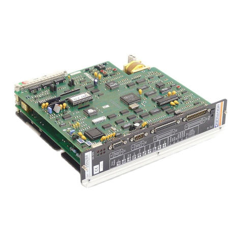
Infranor SMT-BD2 User manual

SMT-BD2
gb
DIGITAL SERVO DRIVE
FOR SINUSOIDAL
BRUSHLESS AC MOTORS
1
SMT-BD2

SMT-BD2
2SMT-BD2

3
SMT-BD2
SMT-BD2
WARNING !
This is a manual describing a series of servo amplifiers having output capability suitable for driving AC brushless
servo motors equipped with an encoder only or an encoder plus Hall effect sensors for the position feedback. This
manual may be used in conjunction with appropriate and referenced drawings pertaining to the various specific
models.
Maintenance procedures should be attempted only by highly skilled technicians (EN 60 204.1 standard)
using proper test equipment.
The conformity with the standards and the "CE" approval are only valid if the items are installed according to the
recommendations of the racks and amplifiers manuals.
Any contact with electrical parts, even after power down, may involve physical damage.
Wait for at least 5 minutes after power down before handling the amplifiers (a residual voltage of several hundreds
of Volts may remain during a few minutes).
INFRANOR drives are conceived to be best protected against electrostatic discharges. However, some
components are particularly sensitive and may be damaged. Before handling the drives and, particularly, before
any contact with the connectors, the user himself must be earthed. Place or store the drives on conducting or
electrostatically neutral areas but not on plastic areas, carpeting or insulation material that may be electrostatically
loaded.
INFRANOR does not assume any responsibility for any physical or material damage due to improper handling or
wrong descriptions of the ordered items.
Infranor reserves the right to change any information contained in this manual without notice.
Any intervention on the items, which is not specified in the manual, will immediately cancel the warranty.
This manual is a translation of the original document and does not commit INFRANOR's responsibility.
The french manual is the only reference document.
©INFRANOR,February 2005. All rights reserved.
Issue:3.0
!

SMT-BD2
4SMT-BD2

SMT-BD2
Contents
CONTENTS............................................................................................................................................. 5
CHAPTER 1 - GENERAL DESCRIPTION ............................................................................................. 7
1-INTRODUCTION............................................................................................................................. 7
2-GENERAL DESCRIPTION.............................................................................................................. 7
3-REFERENCE TO THE STANDARDS............................................................................................. 8
4-REFERENCE TO OTHER DOCUMENTS....................................................................................... 8
CHAPTER 2 – SPECIFICATIONS.......................................................................................................... 9
1-TECHNICAL SPECIFICATIONS..................................................................................................... 9
1.1 - Current ratings for the 220 VAC amplifier version.................................................................... 9
1.2 - Current ratings for the 400 VAC amplifier version.................................................................. 10
1.3 - Other specifications................................................................................................................ 11
2-BLOCK DIAGRAM.........................................................................................................................13
3-MAIN PROTECTIONS .................................................................................................................. 14
3.1 - Displayed protections............................................................................................................. 14
3.2 - Fuse protection....................................................................................................................... 15
CHAPTER 3 - INPUTS - OUTPUTS.................................................................................................... 16
1-CONNECTORS LOCATION......................................................................................................... 16
1.1 - RACK connectors................................................................................................................... 16
1.2 - Amplifier connectors............................................................................................................... 16
2-X5 SERIAL LINK CONNECTOR (SUB D9POINTS MALE)............................................................... 16
3-X1 ENCODER FEEDBACK CONNECTOR (SUB D15 POINTS FEMALE)......................................... 17
3.1 - X1 connector for TTL incremental encoder configuration...................................................... 17
3.2 - X1 connector for TTL incremental encoder & HES configuration.......................................... 18
3.3 - X1 connector for absolute single turn Sin/Cos encoder configuration................................... 19
3.4 - X1 connector for other sin/cos encoder configurations.......................................................... 20
4-X4 COMMAND CONNECTOR (SUB D25 POINTS MALE)................................................................ 21
4.1 - Specification of the analog inputs / outputs............................................................................ 22
4.2 - Specification of the logic inputs / outputs...............................................................................23
5-X2 POSITION OUTPUT CONNECTOR (SUB D25 POINTS FEMALE).............................................. 24
Specification of the TTL encoder output.........................................................................................24
CHAPTER 4 - CONNECTIONS............................................................................................................ 25
1-CONNECTION DIAGRAMS.......................................................................................................... 25
1.1 - Rack power supply and motor connection............................................................................. 25
1.2 - Amplifier i/o connections......................................................................................................... 25
1.3 - RS-232 serial link connection................................................................................................. 27
2-WIRING (ACCORDING TO CEI 801 AND EN 55011 STANDARDS) ....................................................... 28
2.1 - GND wiring and grounding..................................................................................................... 28
2.2 - Motor and sensors cables ...................................................................................................... 28
2.3 - Input command and serial link cables.................................................................................... 28
3-360° SHIELD ON THE CONNECTORS........................................................................................ 29
CHAPTER 5 - ADJUSTABLE FUNCTIONS ........................................................................................ 30
1-HARDWARE ADJUSTMENTS...................................................................................................... 30
2-ADJUSTABLE PARAMETERS ..................................................................................................... 33
CHAPTER 6 - COMMISSIONING......................................................................................................... 34
1-CHECKING THE AMPLIFIER CONFIGURATION........................................................................ 34
1.1 - Standard amplifier configuration............................................................................................. 34
1. 2 - Encoder configuration............................................................................................................ 34
5
Contents

SMT-BD2
1. 3 - Hall Effect Sensors configuration...........................................................................................35
1. 4 - Motor thermal sensor configuration.......................................................................................35
1.5 - Current loops adjustments......................................................................................................36
2-PUTTING INTO OPERATION ....................................................................................................... 38
3-AMPLIFIER COMMISSIONING AND ADJUSTMENT...................................................................38
3.1 - Amplifier setup........................................................................................................................38
3.2 - Motor Hall Effect Sensors adjustment ....................................................................................39
3.3 - Absolute single turn Sin/Cos encoder adjustment..................................................................39
3.4 - Amplifier parameter setting.....................................................................................................40
3.5 - Amplifier auto-tuning with an unbalanced load......................................................................40
3.6 - Saving of the amplifier parameters.........................................................................................41
3.7 - Motor phasing at power up.....................................................................................................41
3.8 - Parameters adjustment to a linear motor ...............................................................................42
CHAPTER 7 – FAULT FINDING...........................................................................................................43
1-SYSTEM FAULT............................................................................................................................43
2-STORED FAULTS.........................................................................................................................43
2.1 - "BUSY" fault...........................................................................................................................43
2.2 - "EEPROM" fault......................................................................................................................44
2.3 - "°C MOTOR" fault...................................................................................................................44
2.4 - "UNDERVOLT." fault ..............................................................................................................44
2.5 - "°C AMPLIFIER" fault..............................................................................................................44
2.6 - "POWER STAGE" fault...........................................................................................................44
2.7 - "HES" fault ..............................................................................................................................44
2.8 - "ENCODER" fault....................................................................................................................45
2.9 - "COUNTING" fault ..................................................................................................................46
2.10 - "I2t" fault ................................................................................................................................47
2.11 - "TRACKING" fault.................................................................................................................47
2.12 - "ADC" fault............................................................................................................................47
3-OPERATING PROBLEMS.............................................................................................................48
3.1 - Motor supplied, but no torque.................................................................................................48
3.2 - Motor does not move..............................................................................................................48
3.3 - Shaft locked, eratic oscillations or rotation at maximum speed..............................................48
3.4 - Discontinuous motor rotation with zero torque positions.......................................................48
3.5 - Motor drift with analog input command at zero speed............................................................48
3.6 - Loud crackling noise in the motor at standstill........................................................................48
3.7 - Loud noise in the motor at standstill and when running.........................................................48
3.8 - Position control not possible with the NC ...............................................................................48
4-SERVICE AND MAINTENANCE ...................................................................................................49
CHAPTER 8 - APPENDIX.....................................................................................................................50
1-USE OF THE LIMIT SWITCHES &"CVO" INPUTS......................................................................50
2-USE OF THE "AMP. READY" &"POWER READY" OUTPUTS....................................................50
3-SPEED FOLLOWING ERROR PROTECTION .............................................................................50
4-I2T PROTECTION..........................................................................................................................51
4.1 - Current limitation in Fusing mode...........................................................................................51
4.2 - Current limitation in Limiting mode .........................................................................................52
5-COGGING COMPENSATION OPTION ........................................................................................52
5.1 - Amplifier configuration ............................................................................................................52
5.2 - cogging compensation setup for rotating motors ...................................................................53
5.3 - cogging compensation setup for linear motors.......................................................................53
6-AMPLIFIER TYPES.......................................................................................................................54
6Contents

SMT-BD2
Chapter 1 - General description
1 - INTRODUCTION
Series SMT-BD2 digital servo modules are sinusoidal PWM power amplifiers that provide speed and torque/force
control for AC brushless motors equipped with encoder only or encoder with Hall Effect Sensors (HES) for the
position feedback. The speed or torque/force input command is a +/-10 V analog signal voltage.
The SMT-BD2 digital servo drive is 220 VAC or 400 VAC main operated. The SMT-BD2 plug-in system with 400
VAC power supply is available as a multiaxis version that can receive up to three axes in a standard 19" rack
including the power supply. The SMT-BD2 plug-in system with 220 VAC power supply is available as a single-axis
block version or as a multiaxis version that can receive up to six axes in a standard 19" rack including the power
supply.
2 - GENERAL DESCRIPTION
Series SMT-BD2 amplifiers have their own DC/DC converter to provide the appropriate supply voltage (+5 V,
+15 V, -15V). The source supply voltage for the logic board is the auxiliary 310 VDC supply voltage. The auxiliary
supply voltage allows to have the position output signals still available when the power supply voltage is turned off.
Each module is packaged as a 6 U "double Eurocard":
- one power board with IGBT transistors
- one logic board with DSP (Digital Signal Processing).
The SMT-BD2 amplifier directly controls the motor torque/force and speed by means of the information provided
by an encoder feedback device. The sinusoidal current commutation based on encoder feedback provides smooth
motor torque/force control.
The SMT-BD2 amplifier can be configurated for various encoder types feedback. The appropriate encoder input
configuration is selectable by jumpers.
- With an incremental encoder only, a motor phasing procedure must be executed at each amplifier power up
before the motor enabling.
- With an incremental encoder + HES feedback from the motor, the motor phasing procedure is no more
necessary and the servo motor can immediately be enabled after the amplifier power up.
- With an absolute single turn SinCos encoder feedback from the motor (Heidenhain ERN 1085 or compatible),
the servo motor can also immediately be enabled after the amplifier power up.
The motor speed or torque/force input command is a +/-10 V analog voltage. The motor position output is
available as two A and B encoder type channels in quadrature, and one Z marker pulse per revolution via RS422
line drivers. The ratio between the number of pulses on the motor encoder and the number of pulses on the SMT-
BD2 amplifier encoder output is programmable.
The amplifier faults are displayed on the front panel and can also be read via the serial link.
All control parameters are programmable by means of the serial link and saved in an EEPROM. The auto-
configuration and auto-tuning functions allow an easy and quick commissioning of the amplifier.
The Visual Drive Setup software, which is IBM-PC compatible with the WINDOWS® operating system, allows the
clear display and easy modification of all amplifier parameters. The Visual Drive Setup software also includes a
digitizing oscilloscope function that is particularly useful for the drive commissioning and maintenance.
7
Chapter 1 - General description

SMT-BD2
3 - REFERENCE TO THE STANDARDS
The 220 VAC version of the SMT-BD2 amplifiers operating in the BF rack, which is equipped with the mains filter
BF-35 or 70, has been approved for its conformity with the Electromagnetic Compatibility standards:
EN 55011, Group 1, Class A regarding the conducted and radiated radioelectric disturbances,
CEI 801 - 2 - 3 - 4 regarding the immunity.
The 220 VAC version of the SMT-BD2 amplifiers operating in the single axis BM20 A – BMM05F – BMM05AF,
which is equipped with appropriate mains filter (FN 612-20/06 or FN 356-16/06) has been approved for its
conformity with the Electromagnetic Compatibility standards:
EN 55011, Group 1, Class A regarding the conducted and radiated radioelectric disturbances,
CEI 801 - 2 - 3 – 4 regarding the immunity.
The 400 VAC version of the SMT-BD2 amplifiers operating in the BF-400 rack, which is equipped with the mains
filter F400-35 or 70, has been approved for its conformity with the Electromagnetic Compatibility standards:
EN 55011, Group 1, Class A regarding the conducted and radiated radioelectric disturbances,
CEI 801 - 2 - 3 - 4 regarding the immunity.
Standard to be applied to the electrical equipments of industrial machines: EN 60204.1.
The SMT-BD2 amplifiers have been "CE" marked since year 2000.
4 - REFERENCE TO OTHER DOCUMENTS
♦BF-400 rack – for the use of the 400 VAC amplifier version in a multiaxis rack.
♦BF rack – for the use of the 220VAC amplifier version in a multiaxis rack.
♦BM20A/BMM05F/05AF single-axis rack – for the use of the 220 VAC amplifier version in a single-axis rack.
8Chapter 1 – General description

SMT-BD2
Chapter 2 – Specifications
1 - TECHNICAL SPECIFICATIONS
1.1 -CURRENT RATINGS FOR THE 220 VAC AMPLIFIER VERSION
Operating voltage DC bus 310 VDC (270 VDC < DC bus < 340 VDC max.)
Auxiliary supply voltage 310 VDC ( 200 VDC < Uaux < 340 VDC max.)
Motor terminal to terminal output voltage 200 Vrms for 310 VDC bus
Authorized output currents for current pulse mode operation (I2t protection in fusing mode)
AMPLIFIER
U rated
Imax (Arms)
Max. authorized rated current (Arms)
of the amplifier
(Vrms) 1 s WITHOUT
FAN*
FAN TYPE
1*
FAN TYPE
2*
SMT-BD2 - 220/04 240 4,4 2
SMT-BD2 - 220/08 240 8,8 4
SMT-BD2 - 220/12 240 13,8 6
SMT-BD2 - 220/17 240 17,7 8,5
SMT-BD2 - 220/30 240 30,8 10 12 15
SMT-BD2 - 220/30r 240 30,8 10 15
SMT-BD2 - 220/45 240 48,6 10 15 20
SMT-BD2 - 220/45r 240 48,6 10 20 23
SMT-BD2 - 220/60 240 61 10 19 25
SMT-BD2 - 220/60r 240 61 12 26 30
SMT-BD2 - 220/70 240 70 25 30 35
SMT-BD2 - 220/100 240 100 25 30 35
Authorized output currents for continuous current mode operation (I2t protection in limiting mode)
AMPLIFIER TYPE
Urated
Imax (Arms)
Max. authorized continuous current (Arms) of
the amplifier
(Vrms) 1 s WITHOUT
FAN*
FAN TYPE
1*
FAN TYPE
2*
SMT-BD2 - 220/04 240 4,4 2
SMT-BD2 - 220/08 240 8,8 4
SMT-BD2 - 220/12 240 13,8 6
SMT-BD2 - 220/17 240 17,7 8,5 8,5
SMT-BD2 - 220/30 240 30,8 8,5 12 15
SMT-BD2 - 220/30r 240 30,8 10 15
SMT-BD2 - 220/45 240 48,6 8,5 15 18
SMT-BD2 - 220/45r 240 48,6 10 20 23
SMT-BD2 - 220/60 240 61 8,5 17 20
SMT-BD2 - 220/60r 240 61 12 26 30
SMT-BD2 - 220/70 240 70 17 30 35
SMT-BD2 - 220/100 240 100 25 30 35
* Maximum ambient temperature = + 40° C, fan 1 = 56 l/s, fan 2 = 90 l/s.
Note: The SMT-BD2-X/Xr amplifier types are equipped with an additional heatsink in order to improve the heat
dissipation and increase their rated current. The width of these amplifier types is then 18 TE instead of 12 TE.
Minimum inductance between phases 1 mH
9
Chapter 2 - Specifications

SMT-BD2
Conformity with the standards: CE approval - EMC standards
with multiaxis power supply configuration Immunity: CEI standards 801- 2 - 3 - 4
BF rack and mains filter BF-35 or 70, Conducted and radiated disturbances: EN 55011,
or SMTB.M 20 A single-axis rack and BF 35 filter. Group 1, class A
"360°" shields; equipotentiality according to the - Electrical standards for industrial machines:
wiring rules. EN 60204.1: - Insulator: 1500 VAC/1 min.
- Leakage current > 3 mA
(EMI filters)
Temperature range * storage - 20°C to + 70°C
* operation 5°C to +40°C
From 40°C on, the rated currents
must be reduced of 3 %/°C.
Max. temperature: 50°C
1.2-CURRENT RATINGS FOR THE 400 VAC AMPLIFIER VERSION
Operating voltage DC bus 565 VDC (480 VDC < DC bus < 685 VDC max.)
Auxiliary supply voltage 310 VDC ( 200 VDC < Uaux < 340 VDC max.)
Motor terminal to terminal output voltage 380Vrms for 565 VDC bus
Authorized output currents for current pulse mode operation (I2t protection in fusing mode)
AMPLIFIER
U rated
Imax (Arms)
Max. authorized rated current
(Arms) of the amplifier
(Vrms) 1 s WITHOUT
FAN*
FAN TYPE
2*
SMT-BD2 - 400/15 400 15.5 5 7.5
SMT-BD2 - 400/30 400 30 8 15
SMT-BD2 - 400/45 400 48 10 19
SMT-BD2 - 400/60 400 60 not used 28
Authorized output currents for continuous current mode operation (I2t protection in limiting mode)
AMPLIFIER TYPE
U rated
Imax (Arms)
Max. authorized continuous
current (Arms) of the amplifier
(Vrms) 1 s WITHOUT
FAN*
FAN TYPE
2*
SMT-BD2 - 400/15 400 15.5 not used 5
SMT-BD2 - 400/30 400 30 not used 10
SMT-BD2 - 400/45 400 48 not used 15
SMT-BD2 - 400/60 400 60 not used 23
* Maximum ambient temperature = + 40° C, fan 2 = 90 l/s.
Minimum inductance between phases 2 mH
Conformity with the standards: CE approval - EMC standards
with multiaxis power supply configuration Immunity: CEI standards 801- 2 - 3 - 4
BF-400 rack and mains filter F400-35 or 70. Conducted and radiated disturbances: EN 55011,
"360°" shields; equipotentiality according to the Group 1, class A
wiring rules. - Electrical standards for industrial machines:
EN 60204.1: - Insulator: 2500 VDC/1 min.
- Leakage current > 3 mA
(EMI filters without condensators)
Temperature range * storage - 20°C to + 70°C
* operation 5°C to +40°C
From 40°C on, the rated currents must be reduced
of3%/°C.
Max. temperature: 50°C
10 Chapter 2 – Specifications

SMT-BD2
1.3 -OTHER SPECIFICATIONS
PWM switching frequency 10 KHz
Current regulator (PI) Adjusted to motor
Current loop bandwidth Cut-off frequency for 45° phase shift > 1 KHz
Internal current limitation Maximum current range : 20 % to 100 % of Imax
Rated current range : 20 % to 50 % of Imax
Imax = amplifier current rating
Analog current limitation input 0 V to 10 V, resolution = 12 bits
100 % to 0 % of the Maximum current value
Maximum current available if not connected
Analog speed command input ±10 V, standard resolution = 12 bits
Resolution = 16 bits optional
Motor accel/decel ramp range From 0 to 30 s between zero speed and
max. speed
Speed regulator P, PI or PI2Sampling period = 0,5 ms
Anti-wind-upsystem of the integrator
Adjustable digital gains
Antiresonance filter
Speed loop bandwidth Cut-off frequency for 45° phase shift
Selectable : 50 Hz, 75 Hz or 100 Hz
(see Note 1)1
Speed range 2048 : 1 with 12 bit input command
32768 : 1 with 16 bit input command
Max. motor speed Adjustable from 100 rpm to 25000 rpm
(see Note 2)2
Hall sensors input Selectable by jumpers : 120° or 60° HES type
5 V or 15 V supply voltage
HES sequence error detection
1Note 1 :
The maximum speed loop bandwidth value not only depends on the amplifier specification but also on the feedback encoder
resolution and the motor mechanical load. The lower the encoder resolution, the lower the servo loop gains and the servo loop
bandwidth, to avoid any motor noise due to signal quantization effect. The mechanical load backlashes and elasticity can also
limit the servo loop gains and bandwidth to avoid mechanical resonances. The optimal servo loop gain value for a given
application can be automatically calculated by using the amplifier Auto-tuning procedure.
2Note 2 :
The Max. motor speed value not only depends on the motor specification but also on the encoder specification. Both following
conditions must be answered for taking into account the maximum encoder pulse frequency value :
Max. motor speed (rpm) < 60 x 106 / Number of encoder pulses per revolution
Max. motor speed (rpm) < 60 x Encoder pulse frequency limit (Hz) / Number of encoder pulses per revolution.For example with
the ROD426 (Heidenhain) series encoder, the pulse frequency limit value is 300 KHz. So, a motor equipped with a ROD426
encoder having a resolution of 5000 ppr cannot exceed 3600 rpm.
11
Chapter 2 - Specifications

SMT-BD2
Encoder input Selectable by jumpers :
Quadrature TTL A & B with Z marker pulse
RS 422 line receiver
maximum pulses frequency: 1 MHz
Resolution: 500 to 106ppr (as from EPROM version 7.1C)
Incremental Sin/Cos encoder
Heidenhain 1 Vcc Sin/Cos type or compatible
Maximum signal frequency: 500 KHz
Resolution:10
3to 106ppr
Absolute single turn Sin/Cos encoder
Heidenhain ERN 1085 or compatible
resolution: 2048 ppr
Encoder output Quadrature TTL A & B with Z marker pulse
RS 422 line driver
Programmable encoder division ratio
output resolution / input resolution : 1, 1/2, 1/4, 1/8
Logic inputs Optoisolated inputs, positive logic,
response time = 0.5 ms:
•Enable/Disable: ENABLE
•Limitswitch+:FC+
•Limitswitch-:FC-
•Current command: CI
•Stop & Phasing command: CV0
Amplifier fault reset: RESET
Logic outputs Relay contact Umax = 50 V,
Imax = 100 mA, Pmax = 10 W
• "Power ready": closed if power OK
• "Amp ready": closed if amplifier OK
• "Phasing OK": closed if motor phasing OK
( incremental encoder without HES)
• "Idyn": open if I2t warning threshold is reached
Monitor outputs 2 channels ANout1 & ANout2
+/-10 V full scale, 12 bit resolution
Programmable output signals on the digitizing
oscilloscope Channel 1 and Channel 2 :
current ref (IDC), current mes (ID,IQ,IMES,I2t),
speed ref (CV), speed mes (GT)
Error display LEDs on front panel and diagnostic via serial link
Parameter setting Serial link RS232 in standard or RS422 optional
Automatic functions Motor parameters adjustment (Auto-phasing)
Regulator gains adjustment (Auto-tuning)
Offset compensation on analog input CV
Altitude 1000 m
Moisture < 50 % at 40°C and < 90 % at 20°C
no condensation
(EN 60204.1 standard)
Cooling Natural convection or forced air, according to the rated
current (see current tables, chapter 2, § 1.1 and 1.2)
12 Chapter 2 – Specifications

SMT-BD2
2 - BLOCK DIAGRAM
The SMT-BD2 servo module block diagram is presented below.
A
B
Z
A
B
Z
CV
ILIM
X1
X2
X4
X5
+5 V
+15 V
-15 V
U
V
W
PR
10
PR
8
310 V DC
Drive
protections
Encoder
input
Encoder
divider
Speed
ramping
Serial
link
Speed Ref
Speed
Supply
voltages
Position
Pulses
counter
Speed
controller
Drive
parameters
Vector
control
Current Ref
Current
limitation
Current
loops
PWM
power stage
Current Mes
Motor phases
Power
supply
Aux. supply
The PR8 and PR10 connectors are not accessible for direct wiring; they are plugged on the BM20A single-axis
rack or on the multiaxes BF rack according to the SMT-BD2 amplifier housing (see chapter 3).
13
Chapter 2 - Specifications

SMT-BD2
3 - MAIN PROTECTIONS
3.1-DISPLAYED PROTECTIONS
PROTECTION ERROR DISPLAY LED*
Amplifier rated current overload I2t 5z
. blinking display = I2t warning threshold is reached (Idyn output) zz
. continuous display = I2t fault (amplifier inhibited in fusing mode)
Encoder cable interruption Encoder z5
zz
Encoder pulses counting error Counting 55
z5
Power stage failure: Power stage 55
. power supply overvoltage zz
. internal overcurrent protection
. short-circuit between phases
. amplifier overtemperature
(220/04 to 220/60 current ratings and 400 VAC amplifier range)
Amplifier overtemperature °C Amp 5z
(only 220/70 and 220/100 current rating amplifiers) 5z
Power supply undervoltage Undervolt. z5
5z
Motor overtemperature °C Motor 55
5z
Hall Effect Sensors or Sin/Cos commutation channels error HES zz
5z
Analog to Digital Conversion error ADC 5z
z5
Speed following error Tracking zz
z5
Fault of the amplifier parameter storage EEPROM 5z
55
Amplifier automatic procedure: Busy 55
. blinking display = procedure operating 55
. continuous display = operating error
* z= LED is unlit 5= LED is lit.
All these faults are memory stored in the amplifier except for the "Undervolt." fault.
The reset of a stored fault can be made:
- by means of the RESET function in the Visual Drive Setup software
- via the fault RESET input (pin 13 of the X4 connector)
- by switching off the amplifier power supply.
14 Chapter 2 – Specifications

15
Chapter 2 - Specifications
SMT-BD2
3.2 -FUSE PROTECTION
3.2.1 - Fuse protection for the 220 VAC amplifier version
F1 : Control of the average DC current of the power board supply (see Hardware adjustments in chapter 5, § 1).
F2 : Control of the average DC current of the logic board supply (see Hardware adjustments in chapter 5, § 1).
AMPLIFIER TYPE F1 F2
Power Logic
SMTBD2-220/04 to 12 10 AT 1 A
SMTBD2-220/17 and 30 15 AT 1 A
SMTBD2-220/45 20 AT 1 A
SMTBD2-220/60 20 AT 1 A
SMTBD2-220/70 - 1 A
SMTBD2-220/100 - 1 A
3.2.2 - Fuse protection for the 400 VAC amplifier version
F2 : Control of the average DC current of the logic board supply (see Hardware adjustments in chapter 5, § 1).
AMPLIFIER TYPE F2
Logic
SMT-BD2 - 400/15 1 A
SMT-BD2 - 400/30 1 A
SMT-BD2 - 400/45 1 A
SMT-BD2 - 400/60 1 A

SMT-BD2
Chapter 3 - Inputs - Outputs
1 - CONNECTORS LOCATION
1.1 -RACK CONNECTORS
For the 400 VAC amplifier version, see BF-400 RACK manual.
For the 220 VAC amplifier version, see SMTB.M 20 A SINGLE-AXIS RACK manual or BF RACK manual.
1.2 -AMPLIFIER CONNECTORS
LED Faults display
X1 Encoder sensor
X5 Serial link
X2 Encoder output
X4 Command
BP Offset
2 - X5 SERIAL LINK CONNECTOR (Sub D 9 points male)
PIN FUNCTION REMARKS
5 0 Volt GND (shield connection if no "360°" connection possible on the connector)
3 TXD Transmit data RS-232
2 RXD Receive data RS-232
6 TXH Transmit data RS-422
7 TXL Transmit data RS-422
8 RXL Receive data RS-422
9 RXH Receive data RS-422
16 Chapter 3 – Inputs-outputs

SMT-BD2
3 - X1 ENCODER FEEDBACK CONNECTOR (Sub D 15 points female)
3.1 –X1 CONNECTOR FOR TTL INCREMENTAL ENCODER CONFIGURATION
The "TTL incremental encoder" configuration is selected according to the following COM and COD jumpers
setting (see chapter 5, section 1: Hardware adjustments).
COD B5
B4
B2
B1
COM
B3
!A wrong jumper configuration may damage the encoder
and amplifier electronics.
The corresponding X1 connector pin function is described below.
PIN FUNCTION REMARKS
1 Marker Z/ Differential input of the encoder marker pulse Z/
9 Marker Z Differential input of the encoder marker pulse Z
2 Channel A/ Differential input of the encoder channel A/
10 Channel A Differential input of the encoder channel A
3 Channel B/ Differential input of the encoder channel B/
11 Channel B Differential input of the encoder channel B
5 +5V Encoder supply voltage (400 mA max. current)
4 GND Encoder supply GND
12 TC Motor thermal sensor input (10 mA max. load current)
13 GND Motor thermal sensor GND
6,7,8 reserved
14,15 reserved
Encoder input specification
+5 V
3,3 KΩ
200 Ω200 Ω
26LS32
X1-9, 10, 11
X1-1, 2,3
ZM
ZM
COD
B2
B1
SMT-BD2
+5 V
Marker pulse enabled
Marker pulse disabled
ZM jumper configuration
COD jumpers configuration
Recommended
driver: 26LS31
Thermal sensor input specification
+15 V +5 V
+15 V
PSTH-A
X1-12
X1-13
SMT-BD2
100 KΩ
100 nF
-
+-
+
10 KΩMN OP
MN OP
PSTH-B
PTC thermal sensor
NTC thermal sensor
MN & OP jumpers configuration
17
Chapter 3 - Inputs - Outputs

SMT-BD2
3.2 –X1 CONNECTOR FOR TTL INCREMENTAL ENCODER &HES CONFIGURATION
The “ TTL incremental encoder & HES” configuration is selected according to the following COM and COD
jumpers setting (see chapter 5, section 1: Hardware adjustments).
COD B5
B4
B2
B1
COM
B3
COD B5
B4
B2
B1
COM
B3
60°HES type 120°HES type
! A wrong jumper configuration may damage the encoder and amplifier electronics.
The corresponding X1 connector pin function is described below.
PIN FUNCTION REMARKS
1 Marker Z/ Differential input of the encoder marker pulse Z/
9 Marker Z Differential input of the encoder marker pulse Z
2 Channel A/ Differential input of the encoder channel A/
10 Channel A Differential input of the encoder channel A
3 Channel B/ Differential input of the encoder channel B/
11 Channel B Differential input of the encoder channel B
5 +5V Encoder supply voltage (400 mA max. current)
4 GND Encoder supply GND
14 HALL U Hall sensor input signal phase U
6 HALL V Hall sensor input signal phase V
7 HALL W Hall sensor input signal phase W
15 +15V Hall sensors supply voltage (50 mA max. current)
12 TC Motor thermal sensor input (10 mA max. load current)
13 GND Hall sensors/Thermal sensor GND
8 reserved
Encoder input specification
+5 V
+5 V
3,3 KΩ
200 Ω200 Ω
26LS32
X1-9, 10, 11
X1-1, 2,3 ZM
ZM
COD
B2
B1
SMT-BD2
Marker pulse enabled
Marker pulse disabled
ZM jumper configuration
COD jumpers configuration
Recommended
driver: 26LS31
Specification of the Hall sensors input
+5 V
10 KΩ
X1-6, 7, 14
X1-13
COM
COM
SMT-BD2
1 KΩB5
B4
B3
B5
B4
B3
60°HES
120°HES
74HC14
1 nF
COM jumpers configuration
18 Chapter 3 – Inputs-outputs

SMT-BD2
3.3 –X1 CONNECTOR FOR ABSOLUTE SINGLE TURN SIN/COS ENCODER CONFIGURATION
The “ Absolute single turn Sin/Cos encoder ” configuration (Heidenhain ERN 1085 or compatible) is selected
according to the following COM and COD jumpers setting (see chapter 5, section 1: Hardware adjustments).
COD B5
B4
B2
B1
COM
B3
!A wrong jumper configuration may damage the
encoder and amplifier electronics.
The corresponding X1 connector pin function description is given below.
PIN FUNCTION REMARKS
1 Reference R/ Differential input of the Sin/Cos encoder reference pulse R/
9 Reference R Differential input of the Sin/Cos encoder reference pulse R
2 Channel A/ Differential input of the Sin/Cos encoder channel A/
10 Channel A Differential input of the Sin/Cos encoder channel A
3 Channel B/ Differential input of the Sin/Cos encoder channel B/
11 Channel B Differential input of the Sin/Cos encoder channel B
6 Channel C/ Differential input of the Sin/Cos encoder channel C/
14 Channel C Differential input of the Sin/Cos encoder channel C
8 Channel D/ Differential input of the Sin/Cos encoder channel D/
7 Channel D Differential input of the Sin/Cos encoder channel D
5 +5V Sin/Cos encoder supply voltage (400 mA max. current)
4 GND Sin/Cos encoder supply GND
12 TC Motor thermal sensor input (10 mA max. load current)
13 GND Motor thermal sensor GND
15 reserved
Specification of the Sin/Cos encoder channels
X1-9, 10, 11
X1-1, 2, 3
SMT-BD2
10 KΩ
10 KΩ
-
+
100 KΩ
100 KΩ
120 ΩB2
B1
ZM
ZM
COD
COD jumpers configuration
Marker pulse enabled
Marker pulse disabled
ZM jumper configuration
Specification of the Sin/Cos commutation channels
X1-14, 7
X1-6, 8
SMT-BD2
10 KΩ
10 KΩ
-
+
50 KΩ
50 KΩ
1 KΩB5
B4
COM
B3
COM jumpers configuration
19
Chapter 3 - Inputs - Outputs

SMT-BD2
3.4 -X1 CONNECTOR FOR OTHER SIN/COS ENCODER CONFIGURATIONS
3.4.1 – X1 CONNECTOR FOR INCREMENTAL SIN/COS ENCODER CONFIGURATION
The “ Incremental Sin/Cos encoder ” configuration (Heidenhain 1Vcc Sin/Cos encoder or compatible) is selected
according to the following COM and COD jumpers setting (see chapter 5, section 1: Hardware adjustments).
COD B5
B4
B2
B1
COM
B3
!A wrong jumper configuration may damage the
encoder and amplifier electronics.
The corresponding X1 connector pin function description is given below.
PIN FUNCTION REMARKS
1 Reference R/ Differential input of the Sin/Cos encoder reference pulse R/
9 Reference R Differential input of the Sin/Cos encoder reference pulse R
2 Channel A/ Differential input of the Sin/Cos encoder channel A/
10 Channel A Differential input of the Sin/Cos encoder channel A
3 Channel B/ Differential input of the Sin/Cos encoder channel B/
11 Channel B Differential input of the Sin/Cos encoder channel B
5 +5V Sin/Cos encoder supply voltage (400 mA max. current)
4 GND Sin/Cos encoder supply GND
12 TC Motor thermal sensor input (10 mA max. load current)
13 GND Motor thermal sensor GND
6,7,8 Reserved
14,15 Reserved
The Sin/Cos channels specifications are given in section 3.3 of this chapter.
3.4.2 – X1 CONNECTOR FOR INCREMENTAL SIN/COS ENCODER & HES CONFIGURATION
The “ Incremental Sin/Cos encoder & HES” configuration (Heidenhain 1Vcc Sin/Cos encoder or compatible) is
selected according to the following COM and COD jumpers setting (see chapter 5, section 1: Hardware
adjustments).
COD B5
B4
B2
B1
COM
B3
COD B5
B4
B2
B1
COM
B3
60°HES type 120°HES type
! A wrong jumper configuration may damage the encoder and amplifier electronics.
The corresponding X1 connector pin function description is given below.
PIN FUNCTION REMARKS
1 Reference R/ Differential input of the Sin/Cos encoder reference pulse R/
9 Reference R Differential input of the Sin/Cos encoder reference pulse R
2 Channel A/ Differential input of the Sin/Cos encoder channel A/
10 Channel A Differential input of the Sin/Cos encoder channel A
3 Channel B/ Differential input of the Sin/Cos encoder channel B/
11 Channel B Differential input of the Sin/Cos encoder channel B
5 +5V Sin/Cos encoder supply voltage (400 mA max. current)
4 GND Sin/Cos encoder supply GND
14 HALL U Hall sensor input signal phase U
6 HALL V Hall sensor input signal phase V
7 HALL W Hall sensor input signal phase W
15 +15V Hall sensors supply voltage (50 mA max. current)
12 TC Motor thermal sensor input (10 mA max. load current)
13 GND Motor thermal sensor GND
8 Reserved
The Sin/Cos channels specifications are given in section 3.3 of this chapter.
The Hall sensor inputs specifications are given in section 3.2 of this chapter.
20 Chapter 3 – Inputs-outputs
Table of contents
Other Infranor Amplifier manuals
