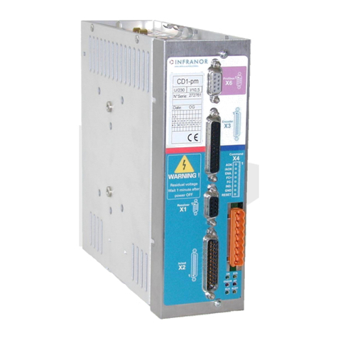
Infranor XtrapulsEasy 60VDC User manual

1
DIGITAL SERVO DRIVES FOR BRUSHLESS AC MOTORS
XtrapulsEasy™60VDC
Embedded module
I n s t a l l a t i o n G u i d e

2
XtrapulsEasy™-DB - Installation Guide
WARNING
This is a general manual describing a series of servo drives having output capability suitable for driving AC
brushless sinusoidal servo motors.
Please see also:
oXtrapulsEasy™ User Guide for the operation of the drive (commissioning, configuration, ...)
oXtrapulsEasy™ DB STO for the Safe Torque Off function
oGem Drive Studio software Quick Start manual for the drive parameterization.
Instructions for storage, use after storage, commissioning as well as all technical details require the
MANDATORY reading of the manual before getting the drives operational.
Maintenance procedures should be attempted only by highly skilled technicians having good knowledge
of electronics and servo systems with variable speed (EN 60204-1 standard) and using proper test
equipment.
The conformity with the standards and the "CE" approval is only valid if the items are installed according to the
recommendations of the drive manuals. Connections are the user's responsibility if recommendations and
drawings requirements are not met.
INFRANOR does not assume any responsibility for any physical or material damage due to improper handling or
wrong descriptions of the ordered items.
Any intervention on the items, which is not specified in the manual, will immediately cancel the warranty.
INFRANOR reserves the right to change any information contained in this manual without notice.
!
WASTE DISPOSAL
In order to comply with the 2002/96/EC directive of the European Parliament and of the Council of
27 January 2003 on waste electrical and electronic equipment (WEEE), all INFRANOR devices
are labelled with a sticker symbolizing a crossed-out dustbin as shown in Appendix IV of the
2002/96/EC Directive.
This symbol indicates that INFRANOR devices shall be eliminated by selective disposal and not
with household waste.
Any contact with electrical parts, even after power down, may involve physical damage.
Wait at least 10 minutes after power down before handling the drives (a residual voltage of several hundreds
of volts may remain during a few minutes).
ESD INFORMATION (ElectroStatic Discharge)
INFRANOR drives are designed for being best protected against electrostatic discharges. However,
some components are particularly sensitive and may be damaged if the drives are not properly stored
and handled.
STORAGE
-The drives must be stored in their original packaging.
-When taken out of their packaging, they must be stored positioned on one of their flat metal
surfaces and on a dissipating or electrostatically neutral support.
-Avoid any contact between the drive connectors and material with electrostatic potential
(plastic film, polyester, carpet…).
HANDLING
-Never get in contact with the connectors.
Caution: Hot surface, risk of burns (wait for cooling after power down).

3
Content
XtrapulsEasy™-DB - Installation Guide
Content
CONTENT............................................................................................................................................... 3
CHAPTER 1 - GENERAL....................................................................................................................... 5
1.1 -INTRODUCTION.......................................................................................................................... 5
1.2 -DESCRIPTION / COMPLIANCE WITH THE STANDARDS......................................................... 5
1.2.1 - General description ............................................................................................................... 5
1.2.2 - Reference to the standards: .......................................................................................... 6
1.3 -OTHER DOCUMENTS................................................................................................................. 6
1.4 -ORDERING CODE....................................................................................................................... 7
1.5 -ACCESSORIES ........................................................................................................................... 7
CHAPTER 2 - SPECIFICATIONS........................................................................................................... 8
2.1 -MAIN TECHNICAL DATA............................................................................................................. 8
2.1.1 - XtrapulsEasy™-ak-60/45-DB ................................................................................................ 8
2.1.2 - Technical specifications......................................................................................................... 8
2.2 -DIMENSIONS AND MOTHERBOARD FOOTPRINT .......................................................................... 11
CHAPTER 3 - INPUTS - OUTPUTS..................................................................................................... 12
3.1 -DISPLAY.................................................................................................................................... 12
3.1.1 - Leds..................................................................................................................................... 12
3.1.2 - CANopen® communication bus .......................................................................................... 13
3.2 -X10 CONNECTOR: FEEDBACK /CAN /TTL HALL /I/O........................................................... 13
3.2.1 Resolver feedback................................................................................................................. 13
3.2.2 Encoder feedback.................................................................................................................. 15
3.2.3 Equivalent input/output circuits.............................................................................................. 15
3.3 -X9: POWER CONNECTORS..................................................................................................... 17
3.4 -MECHANICAL MOUNTING............................................................................................................... 17
CHAPTER 4 - DESIGN RECOMMENDATIONS.................................................................................. 18
4.1 -MOTHERBOARD DESIGN................................................................................................................ 18
4.1.1 - Copper section..................................................................................................................... 18
4.1.2 - Power and signal separation............................................................................................... 18
4.1.3 - External capacitors and decoupling..................................................................................... 18
4.1.3.1 - 24V supply ....................................................................................................................................18
4.1.3.2 - DC Bus Capacitors........................................................................................................................18
4.1.4 - Shielding and grounding...................................................................................................... 19
4.2 -PROTECTIONS .............................................................................................................................. 19
4.2.1 - Auxiliary power supply......................................................................................................... 19
4.2.2 - Power supply....................................................................................................................... 19
4.3 -ACCESSORIES AND CONNECTIONS ..................................................................................... 20
4.3.1 - Connection of a backup battery........................................................................................... 20
4.3.2 - Multi-axis connection of the serial link................................................................................. 20
4.4 -WIRING INSTRUCTIONS.......................................................................................................... 20
4.4.1 - Motor, resolver and encoder cables.................................................................................... 20
4.4.2 - Serial link and CAN communication cables......................................................................... 21
4.4.3 - Very important ..................................................................................................................... 21
4.4.4 - Connection of the 24VDC supply........................................................................................... 22
4.4.5 - Connection of the DC Bus................................................................................................... 22
4.4.6 - Starting procedure............................................................................................................... 22
4.5 -CHAINING DRIVES ......................................................................................................................... 23
4.5.1 - AOK chaining with XtrapulsEasy™ drives only................................................................... 23
4.5.2 - AOK chaining with XtrapulsEasy™ and XtrapulsPac drives together................................. 23

4
Content
XtrapulsEasy™-DB - Installation Guide
CHAPTER 5 - APPENDIX..................................................................................................................... 24
5.1 -DEVELOPMENT KIT "DEV01".........................................................................................................24
5.1.1 - Overview of the development kit.......................................................................................... 24
5.1.2 - Connector details.................................................................................................................25
5.1.2.1 - X1 connector: Feedback ...............................................................................................................25
5.1.2.2 - X2 connector: Input / Output..........................................................................................................25
5.1.2.3 - X3 connector: +24 V......................................................................................................................26
5.1.2.4 - X4 connector: Motor phases and power supply.............................................................................26
5.1.2.5 - X5 connector: CAN & RS232 ........................................................................................................26
5.1.2.6 - X10A connectors...........................................................................................................................27
5.1.3 - Jumper configuration of the capacitor bus...........................................................................27
5.1.4 - Layout..................................................................................................................................28
5.2 -LOW OPERATING VOLTAGE....................................................................................................29
5.3 -MAINTENANCE .........................................................................................................................29
5.3.1 - Periodical checking.............................................................................................................. 29
5.3.2 - Warranty ..............................................................................................................................30
5.4 -OPERATING ENVIRONMENT CONDITIONS ...........................................................................30

5
XtrapulsEasy™-DB - Installation Guide
Chapter 1 - General
Chapter 1 - General
1.1 - INTRODUCTION
XtrapulsEasy™ all-digital drives with sinusoidal PWM control are servo drives that provide the control of
brushless AC motors.
The standard control interface can be:
- CANopen®
1
,
- Analog.
Series XtrapulsEasy™ drives are dedicated to basic applications that do not have a high level of requirements in
terms of functionalities and where cost effectiveness is very important.
The XtrapulsEasy™ drive can be used in following typical applications:
Axes controlled by CANopen®fieldbus according to the DS402 protocol,
Stand-alone operation as a sequencer with control by means of logic I/Os,
Traditional analog speed drive with +/- 10V command and A, B, Z encoder output for the position feedback.
The configuration and parameterization software tool Gem Drive Studio allows a quick configuration of the
XtrapulsEasy™ drives according to the target application.
Thanks to its pluggable module layout, the XtrapulsEasy™DB drive - allows the user optimizing the global
solution in terms of size, weight, and functionalities integration.
1.2 - DESCRIPTION / COMPLIANCE WITH THE STANDARDS
1.2.1 - General description
The XtrapulsEasy™ drive can be configured in 4 feedback modes:
- Resolver
- TTL encoder with or without Hall effect sensors
- Hall effect sensors only
- Sensorless
The appropriate position sensor configuration is software selectable and saved in the drive.
When using a high resolution position sensor, this sensor ensures a high dynamic motor torque/force control and
full torque/force is available at low speed and at standstill.
With a resolver sensor feedback, the motor absolute position value over one revolution is available and the
servo motor can immediately be enabled after the drive power up.
With an incremental encoder only, a motor phasing procedure (Phasing) must be executed at each drive
power up before the motor enabling.
With an incremental encoder + Hall Effect Sensors (HES) feedback, the motor phasing procedure is no more
necessary and the servo motor can immediately be enabled after the drive power up.
With only a Hall effect Sensor (HES) feedback, the position resolution is low, involving reduced dynamic
performances.
In sensorless mode, a motor phasing procedure is automatically executed at the drive enabling.
1
CANopen®is a registered Community Trademark of CAN in Automation e.V, Germany.

6
XtrapulsEasy™-DB - Installation Guide
Chapter 1 - General
Series XtrapulsEasy™ drives have their own DC/DC converter to provide the voltages required for the drive
operation with a 24VDC +/- 15 % supply source which is generally available on machines. The auxiliary supply
allows keeping the drive logic supplies after the power supply has been switched off. Thus, the position output
can be kept without new initializations of the machine. A 24VDC battery supply with specific wiring allows keeping
the position even after switching off the auxiliary 24VDC supply. This wiring can be used for getting an "absolute"
servo drive operation.
All control parameters are programmable via a serial link (e.g. RS-232) and saved in a memory. The auto-tuning
and auto-phasing functions allow a quick and easy commissioning of the drive.
Thanks to the Gem Drive studio software tool, which is PC compatible with the WINDOWS® operating system, all
drive parameters can be displayed and easily modified.
Gem Drive Studio also allows the quick configuration of the XtrapulsEasy™ drive according to the application
type.
The Digital Oscilloscope of this software tool ensures an easy and quick commissioning of the drive.
The Gem Drive Studio software also allows parameterization and diagnostic in a multi-axis configuration.
1.2.2 - Reference to the standards:
Electromagnetic compatibility
According to the Directive 2004/108/EC, the actuators are complying with the Electromagnetic Compatibility
standards regarding the power servos, referenced in the EN 61800-3 –Part 3 about "Electrical power servo
systems with variable speed":
EMISSION
EN 61800-3 C1 category equipment –table 14
IMMUNITY
EN 61000.4-2-3-4.5-6 Expected use: Second environment including other areas than those
directly supplied with electricity by a public low-voltage mains network.
NOTE: Industrial areas and technical rooms are examples of second environment.
Security:
73/23/EEC modified by the directive 93/68/EEC: Low voltage directive
EN 60204-1: Safety of machinery: electrical equipment of machines
EN 61800-5-2: Adjustable speed electrical power drive systems:
Safety requirements - Functional
EC conformity of the XtrapulsEasy™ drive
1.3 - OTHER DOCUMENTS
XtrapulsEasy™ User guide.
XtrapulsEasy™ DB STO manual.
Gem Drive Studio software Quick Start manual.

7
XtrapulsEasy™-DB - Installation Guide
Chapter 1 - General
1.4 - ORDERING CODE
XtrapulsEasy-ak-60/45-DB
Logic version
ak:
Analog and CANopen® interfaces
Voltage range
60:
60VDC
Current rating for 60VDC drives
45:
45Arms
Mounting version
DB:
Embedded module
1.5 - ACCESSORIES
Ordering code: Easy-dev01
This product provides external connectors identical to XtrapulsEasy™ 60VDC standard series (see section 5.1).

8
Chapter 2 –Specifications
XtrapulsEasy™-DB - Installation Guide
Chapter 2 - Specifications
2.1 - MAIN TECHNICAL DATA
2.1.1 - XtrapulsEasy™-ak-60/45-DB
Design
Pluggable module
Operating power supply voltage (1)
24 to 60VDC +/- 10 %
Grounded reference voltage
Undervoltage threshold (1)
25VDC
Overvoltage threshold (1)
85VDC
Motor phase-to-phase output voltage
95% of power supply voltage
Braking system
No braking system integrated
Minimum phase-to-phase inductance (1)
0.2mH
Galvanic isolated auxiliary supply voltage
24VDC +/-15% - 100mA (without output loads)
Grounded reference voltage.
(1) These values correspond to the default configuration of the drive. For lower operating voltage, see section 5.2
"Low operating voltage".
OUTPUT CURRENT RATINGS
TYPE
Max. output
current for
3 s (Arms) (1)
Rated output
current (Arms)
Power
losses
at rated
current
(W)
Rated input
current
(Arms)
Maximum
protection line
circuit fuses
Short-circuit
current
Easy-ak-60/45-DB
45
13
6,5
15,9
16
5kA
Maximum surrounding air temperature: 40°C.
2.1.2 - Technical specifications
Servo loops: current, speed, position
Digital
Position sensor
Transmitter resolver
TTL Incremental encoder
TTL Incremental encoder + Hall Effect sensors
Hall Effect Sensors only
Power protections
See section 3.1.1 - LEDs
Switching frequency
8 kHz, 16kHz
Analog input 1
+10V (resolution: 12bit)
Speed and position regulators
Sampling period = 0.5ms
Anti-wind-up system of the integrator
Anti-resonance filter
Adjustable digital gains

9
XtrapulsEasy™-DB - Installation Guide
Chapter 2 –Specifications
Speed loop bandwidth
Selectable cut-off frequency for 45° phase shift:
50 Hz (low), 75 Hz (medium) or 100 Hz (high)
Current loop bandwidth
Cut-off frequency for 45° phase shift:
500 Hz (low) or 1000 Hz (high)
Max. motor speed
Adjustable from 100 to 25'000 rpm
Drive reaction time
(initialization delay before PWM on)
6.25ms
Encoder position output
Encoder output is only available if TTL encoder is connected.
Resolver input
Software selectable:
Transmitter resolver:
Excitation frequency: 8kHz
Max. output current = 30mA
Transformation ratio: 0.3 to 0.5 (other values are factory set)
Encoder input
Software selectable:
Quadrature signals A& B + one Z marker pulse per revol.
Line receiver RS-422
Max. frequency of encoder pulses: 1MHz
Resolution: 500 to 106ppr
Hall sensors input
5V to 24V positive logic voltage accepted
External HES supply voltage required if different from 5V
HES sequence error detection
Logic inputs
4 GND referenced logic inputs:
- 3 software configurable logic inputs - Response time: 500μs
- 1 input dedicated to the STO/INHIBIT function
Response time: < 50ms
Capture input
1 programmable input (IN1, IN2 or IN3)
Response time: 62.5μs
Logic outputs
2 software configurable logic outputs type PNP "high side"
24VDC, max. 500mA
Response time: 500μs
Error display
Front panel LEDs + diagnostic via serial link or CAN bus
Motor and application parameterization
Serial link RS-232 or bus interface with CANopen®
communication protocol
CAN interface
CANopen® Protocol (DS301, DSP402)
Automatic functions
Drive adjustment to the motor (AUTO-PHASING)
Adjustment of the servo loops (AUTO-TUNING)
MTBF (Mean Time Between Failures)
> 100'000 hours
Maximum surrounding air temperature
- Operation: -25°C to +50°C: from 40°C, the rated current
must be reduced by 3% per additional Celsius degree
- Storage: -25°C to +70°C
Altitude
1000m
Moisture
< 50% at 40°C and < 90% at 20°C: EN 60204-1 standard
Condensation prohibited (storage and operation)

10
Chapter 2 –Specifications
XtrapulsEasy™-DB - Installation Guide
Cooling
Natural air convection
Check for free air convection and for no obstruction of the
upper or lower air admissions.
Environment
The hosting printed circuit board must be mounted inside a
cabinet protecting the drive from conducting dust and
condensation (pollution degree 2 environment) and according
to the room temperature requirements.
Weight
0,026kg

11
XtrapulsEasy™-DB - Installation Guide
Chapter 2 –Specifications
2.2 - DIMENSIONS AND MOTHERBOARD FOOTPRINT
The mechanical layout to be implemented on the motherboard is shown below:

12
XtrapulsEasy™-DB - Installation Guide
Chapter 3 –Inputs-Outputs
Chapter 3 - Inputs - Outputs
3.1 - DISPLAY
3.1.1 - Leds
RUN: status of the CANopen® communication bus connection.
ERROR: faults grouped on the ‘ERROR’ LED: these errors are coded and can be displayed by means of the
parameter setting software.
ERROR LED unlit if no fault.
ERROR LED flashing: ‘UNDERVOLTAGE’ error: no power supply voltage.
ERROR LED continuously lit: fault.
The ERROR LED groups the following faults:
Power supply overvoltage.
24VDC logic supply < 17.5VDC.
Motor phase / GND short-circuit.
Motor phase / motor phase short-circuit, power stage overtemperature, defective IGBT module.
Triggering of the I2t protection.
Counting error.
Position following error
EEPROM error.
Procedure execution error (busy).
Current offset error.
Drive rating overcurrent.
Motor temperature error.
Resolver or encoder cable interruption.
Hall sensors or absolute encoder error.
Notes
Any of these errors (except for the "Undervolt." error) involves:
The continuous lighting of the red ERROR LED,
The drive disabling,
The motor brake control,
The disabling of the AOK output. This output must be wired as described in the connection diagram of
section 4.5, in order to switch-off the power supply.
The ‘UNDERVOLTAGE’ error (flashing ERROR LED) involves:
The drive disabling,
The motor brake control.
RUN (green)
ERROR (red)

13
XtrapulsEasy™-DB - Installation Guide
Chapter 3 –Inputs-Outputs
3.1.2 - CANopen® communication bus
RUN: The CANopen® RUN LED indicates the status of the NMT state machine (see DS-301 –9.52 NMT state
machine):
CAN RUN LED
STATUS
FLASHING
STOP
BLINKING
PRE-OPERATIONAL
ON
OPERATIONAL
See "DR-303-3 Indicator specification" for more information.
Note:
Each drive of the network must be configured with one single address.
The factory-set addressing is address 1 and the default communication speed is 1Mbit.
3.2 - X10 CONNECTOR: FEEDBACK / CAN / TTL HALL / I/O
The feedback and I/O connector is a 2.54mm pitch 2x15 pins header.
Recommended mating references are listed below:
Manufacturer
REFERENCE
FCI
87606-315LF
HARWIN
M20-7831546
SAMTEC
SSQ-115-01-G-D
E-TEC
BL2-030-S842-55
The pinout of this connector is described below.
3.2.1 Resolver feedback
PIN
FUNCTION
I/O
DESCRIPTION
1
RS232 TX
O
Transmit data RS-232
3
RS232 RX
I
Receive data RS-232
2
CAN H
IO
Line CAN-H (dominant high)
4
CAN L
IO
Line CAN-L (dominant low)
12
+24V
I
24VDC supply: +/- 15%
Consumption: 100mA without digital output loads
6
GND
14
GND
17
GND
30
GND
8
OUT1
O
"high side" logic outputs 24V / 500mA
10
OUT2
O
19
IN1
I
All logic inputs are referenced to GND
Vin voltage = 18V < Vin < 27V
Input impedance Zin = 10kΩ
21
IN2
I
23
IN3
I
25
IN4
I
15
+5V
O
Encoder supply voltage (max. current = 300mA)
26
R1 (reference +)
O
Resolver signal
24
R2 (reference -)
O
Resolver signal
16
S3 (cosine +)
I
Resolver signal
18
S1 (cosine -)
I
Resolver signal
1000ms
200ms
ON
OFF
200ms
200ms
ON
OFF

14
XtrapulsEasy™-DB - Installation Guide
Chapter 3 –Inputs-Outputs
20
S2 (sine +)
I
Resolver signal
22
S4 (sine -)
I
Resolver signal
29
IN_ANA1+
I
Analog input nr. 1
Differential input +/-10V *
27
IN_ANA1-
I
28
TM+
I
Motor thermal sensor input. The valid measurement
range is between
100Ω and 44kΩ measured between TM+ and GND
9
HALL_U
I
Hall sensor input signal phase U
11
HALL_V
I
Hall sensor input signal phase V
13
HALL_W
I
Hall sensor input signal phase W
Others
Reserved
(*) For a non differential input signal, ANA1- must be connected to GND on the drive side

15
XtrapulsEasy™-DB - Installation Guide
Chapter 3 –Inputs-Outputs
3.2.2 Encoder feedback
PIN
FUNCTION
I/O
DESCRIPTION
1
RS232 TX
O
Transmit data RS-232
3
RS232 RX
I
Receive data RS-232
2
CAN H
IO
Line CAN-H (dominant high)
4
CAN L
IO
Line CAN-L (dominant low)
12
+24V
I
24VDC supply: +/- 15%
Consumption: 300 mA without digital output loads
6
GND
14
GND
17
GND
30
GND
8
OUT1
O
"high side" logic outputs 24V / 500mA
10
OUT2
O
19
IN1
I
All logic inputs are referenced to GND
Vin voltage = 18V < Vin < 27V
Input impedance Zin = 10kΩ
21
IN2
I
23
IN3
I
25
IN4
I
15
+5V
O
Encoder supply voltage (max. current = 300mA)
18
A channel
I
Differential input of the encoder channel A
16
A/ channel
I
Differential input of the encoder channel A/
22
B channel
I
Differential input of the encoder channel B
20
B/ channel
I
Differential input of the encoder channel B/
5
Z/ marker pulse
I
Differential input of the encoder marker pulse Z/
7
Z marker pulse
I
Differential input of the encoder marker pulse Z
29
IN_ANA1+
I
Analog input nr. 1
Differential input +/-10V *
27
IN_ANA1-
I
28
TM+
I
Motor thermal sensor input. The valid measurement
range is between
100Ω and 44kΩ measured between TM+ and GND
9
HALL_U
I
Hall sensor input signal phase U
11
HALL_V
I
Hall sensor input signal phase V
13
HALL_W
I
Hall sensor input signal phase W
Others
Reserved
(*) For a non differential input signal, ANA1- must be connected to GND on the drive side
3.2.3 Equivalent input/output circuits
SPECIFICATION OF THE INCREMENTAL
TTL ENCODER INPUT LINES
A, B, Z
+5V
Receiver
26LS32
4.9K
A/, B/, Z/
Min.
Max.
High input voltage
3.3 V
24 V + 15 %
Low input voltage
0 V
0.6 V
Hall inputs are compatible with open collector
outputs, without any external component.
SPECIFICATION OF THE HALL
SENSOR INPUT LINES
+5V
10K
Hall U, V, W
GND
10K
10K

16
XtrapulsEasy™-DB - Installation Guide
Chapter 3 –Inputs-Outputs
Specification of the logic input
Minimum
Recommended
Maximum
High input voltage
18V
24V
27V
Low input voltage
0V
0V
5V
Specification of the logic outputs OUT1 and OUT2
Digital outputs can be paralleled in order to increase the maximum output current.
Be careful to connect all paralleled outputs to the same drive signal.
Paralleled outputs
Output voltage
Maximum output current
1
24V
500mA
2
24V
900mA
Specification of the analog inputs ANA1+/-

17
XtrapulsEasy™-DB - Installation Guide
Chapter 3 –Inputs-Outputs
3.3 - X9: POWER CONNECTORS
The power connector is a 2,54mm pitch 2x17 header.
Recommended mating references are listed below
:MANUFACTURER
REFERENCE
FCI
87606-317LF
HARWIN
M20-7831746
SAMTEC
SSQ-117-01-G-D
E-TEC
BL2-034-S842-55
PIN
SIGNAL
I/O
FUNCTION
DESCRIPTION
1
U
O
Motor phase U
Motor cable shield must be connected over 360°.
2
3
4
5
6
7
V
O
Motor phase V
8
9
10
11
12
13
W
O
Motor phase W
14
15
16
17
18
19
DC-
IO
Negative DC bus voltage
DC- is internally connected to GND
20
21
22
23
24
25
26
27
DC+
IO
Positive DC bus voltage
24V to 60V power supply
28
29
30
31
32
33
34
IMPORTANT
Motor cable must be shielded.
The 360° shield connection must be ensured by metallic collars and connected to the ground reference potential.
The GND wire of the motor cable MUST be connected to
See section 4.1 for grounding and shielding precautions.
3.4 - MECHANICAL MOUNTING
Four 3,2mm holes are provided to allow mechanical fasten of the drive.
Recommended spacer length is 12mm.

18
Chapter 4 - Connections
XtrapulsEasy™-DB - Installation Guide
Chapter 4 - Design recommendations
4.1 - MOTHERBOARD DESIGN
4.1.1 - Copper section
The copper section for motor phases U V W and power source must be at least 0.3mm² on external layers.
However, in order to optimize the thermal behaviour (temperature rise less than 10°C), we recommend to
maximize the current ability of the design by:
- Using at least 4-layer PCBs and at least 35µm finished copper thickness,
- Using maximum trace width according to the connector pitch = 7mm.
Note: External layers allow a current 3 times higher than internal layers, thanks to natural convection.
On a multi-layer PCB, power trace patterns should be stacked to avoid coupling problems.
4.1.2 - Power and signal separation
Best practice is to keep a physical separation between power and low voltage signals on all stacked layers at the
same time:
- It allows thermal separation,
- It allows electrical separation.
To avoid coupling between low level signals and power traces, the following rules must be observed:
Never route together the power phases and the feedback signals.
Keep a GND trace between the power phases (or power source) and logic signals.
Differential signals (ex: CANOpen, Resolver) must be routed in respect of differential state of the art rules.
4.1.3 - External capacitors and decoupling
4.1.3.1 - 24V supply
A 220µF 35V aluminum capacitor placed on the host PCB near each drive is recommended for a proper +24V
decoupling.
Note: The 24 V and power supply protection on source side must be ensured by the user.
4.1.3.2 - DC Bus Capacitors
At least, a 470µF /100V capacitor must be placed at the nearest of each drive.
If the DC bus power supply is provided by a battery, the energy reflected by the motor during deceleration phases
will recharge it.
Check the battery can support the max current reflected.
If the DC bus power supply is provided by a no current-reversible power supply (e.g. switch-mode power supply),
additional capacitors will be necessary.
Proceed by increasing the total amount of the DC bus capacitor bank until the overvoltage fault does not appear
anymore during deceleration phases.
Note: Emergency stops are generally the most regenerative phase since all axes decelerate simultaneously. A
protection diode may be necessary to avoid overvoltage on non-reversible supply.

19
Chapter 4 - Connections
XtrapulsEasy™-DB - Installation Guide
4.1.4 - Shielding and grounding
A good shielding and ground connection of the cables is mandatory for ensuring a proper operation.
To ensure the correct EMC grounding of the whole system (drive-cable-motor), the following rules must be
observed:
- The motherboard must be mounted at least on an aluminum chassis (a closed metal case is even
better)
- The motor cable shield must be connected to the chassis.
A mounting example is shown below:
4.2 - PROTECTIONS
4.2.1 - Auxiliary power supply
The final user has to provide an isolated auxiliary 24VDC +/-15% supply (e.g. with isolation transformer) for the
auxiliary supply input, protected by a 3A fuse or circuit breaker.
4.2.2 - Power supply
The recommended protection is a D-type: current for 1s = 10 x rated current.
The maximum power supply short-circuit power must not exceed 5000Arms.
On XtrapulsEasy™ drives, the recommended fuse or circuit breaker rating is:
Recommended D-type
protection rating
Easy-ak-60/45-DB
16A

20
Chapter 4 - Connections
XtrapulsEasy™-DB - Installation Guide
4.3 - ACCESSORIES AND CONNECTIONS
4.3.1 - Connection of a backup battery
The XtrapulsEasy™ drive consumption is less than 100mA with 24VDC. So, a 24V / 30A/h battery can keep the
drive powered during approx. 10 days. This backup method is interesting for saving the machine initialization as
well as the axis position even when moving with the mains switched off.
4.3.2 - Multi-axis connection of the serial link
The parameterization of all axes is made by one single connection to the first axis via the serial link RS232. The
other axis are parameterized via the CAN bus.
4.4 - WIRING INSTRUCTIONS
According to the EN61000.4-2-3-4-5 and EN55011 standards.
4.4.1 - Motor, resolver and encoder cables
Motors, resolvers and encoders are grounded via their housing.
Cable inputs must be made by means of metal connectors with collars allowing the 360° shield connection.
The resolver cable must be pair twisted and shielded (sin, cos, ref.). Motor cables MUST also be shielded and
connected over 360° at both ends.
Encoder inputs A, B, C, D, Z and R require pair twisted and shielded cables. The shield must have a 360°
connection via metallic collars at both ends.
RS 232
Setup
monitoring
Host controller
CANopen® DS402
CAN bus
CAN bus
RT
R
T
RT = 120Ωterminal resistor connected between CAN-L and CAN-H lines
Table of contents
Other Infranor Control Unit manuals
Popular Control Unit manuals by other brands

MPP Solar
MPP Solar Wi-Fi Card user manual
Nvidia
Nvidia Jetson Orin NX Series Product guide
BYOC
BYOC Large Beaver PCB instructions
Marshall Excelsior
Marshall Excelsior ME990-3F Installation and operating manual
DMP Electronics
DMP Electronics Wiegand 734N installation guide
DURBIN
DURBIN Synergy Series Installation and operation manual
