Infranor SMT-BD1/p Series User manual

SMT-BD1/p - CD1-p - User manual 1
SMT-BD1/p - CD1-p - User manual
SMT-BD1/p
CD1-p
gb
PROFIBUS
POSITIONER
User manual
INFRANOR
®

SMT-BD1/p - CD1-p - User manual
2
SMT-BD1/p - CD1-p - User manual

SMT-BD1/p - CD1-p - User manual 3
SMT-BD1/p - CD1-p - User manual
WARNING !
This is a general manual describing a series of servo amplifiers having output capability suitable for driving AC
brushless sinusoidal servo motors. This manual may be used in conjunction with appropriate and referenced
drawings pertaining to the various specific models.
Instructions for storage, use after storage, commissioning as well as all technical details require the MANDATORY
reading of the manual before getting the amplifiers operational.
Maintenance procedures should be attempted only by highly skilled technicians having good knowledge
of electronics and servo systems with variable speed (EN 60204-1 standard) and using proper test
equipment.
The conformity with the standards and the "CE" approval is only valid if the items are installed according to the
recommendations of the amplifier manuals. Connections are the user's responsibility if recommendations and
drawings requirements are not met.
INFRANOR does not assume any responsibility for any physical or material damage due to improper handling or
wrong descriptions of the ordered items.
Any intervention on the items, which is not specified in the manual, will immediately cancel the warranty.
Infranor reserves the right to change any information contained in this manual without notice.
© INFRANOR, October 2005. All rights reserved.
Edition: 2.4
!
Any contact with electrical parts, even after power down, may involve physical damage.
Wait for at least 5 minutes after power down before handling the amplifiers (a residual voltage of several
hundreds of volts may remain during a few minutes).
ELIMINATION
In order to comply with the 2002/96/EC directive of the European Parliament and of the Council of
27 January 2003 on waste electrical and electronic equipment (WEEE), all INFRANOR devices
have got a sticker symbolizing a crossed-out wheel dustbin as shown in Appendix IV of
the 2002/96/EC Directive.
This symbol indicates that INFRANOR devices must be eliminated by selective disposal and not
with standard waste.
ESD INFORMATION (ElectroStatic Discharge)
INFRANOR amplifiers are conceived to be best protected against electrostatic discharges. However,
some components are particularly sensitive and may be damaged if the amplifiers are not properly
stored and handled.
STORAGE
- The amplifiers must be stored in their original package.
- When taken out of their package, they must be stored positioned on one of their flat metal
surfaces and on a dissipating or electrostatically neutral support.
- Avoid any contact between the amplifier connectors and material with electrostatic potential
(plastic film, polyester, carpet…).
HANDLING
- If no protection equipment is available (dissipating shoes or bracelets), the amplifiers must
be handled via their metal housing.
-
Never get in contact with the connectors

SMT-BD1/p - CD1-p - User manual
4
SMT-BD1/p - CD1-p - User manual
Windows®is a registered trade-mark of MICROSOFT®CORPORATION.
STEP7®is a registered trade-mark of SIEMENS®.

Contents 5
SMT-BD1/p - CD1-p - User manual
Contents
PAGE
CONTENTS............................................................................................................................................. 5
CHAPTER 1 - GENERAL DESCRIPTION ............................................................................................. 7
1-INTRODUCTION............................................................................................................................. 7
2-ARCHITECTURE OF APOSITIONER............................................................................................ 8
CHAPTER 2 - COMMISSIONING........................................................................................................... 9
1-CHECKING THE POSITIONER HARDWARE CONFIGURATION............................................... 10
2-PUTTING INTO OPERATION ....................................................................................................... 10
3-MOTOR ADJUSTMENT................................................................................................................ 10
3.1 - Motor parameter setting ......................................................................................................... 10
3.2 - Current loops (CD1-p) ............................................................................................................ 10
3.3 - Adjustment to a new motor..................................................................................................... 11
3.4 - I2t protection (BD1p) ............................................................................................................... 11
3.5 - I2t protection (CD1p)............................................................................................................... 13
3.6 - Rotation/counting direction..................................................................................................... 14
3.7 - Maximum application speed................................................................................................... 14
3.8 - Thermal sensor configuration on the CD1-p positioner ......................................................... 14
4-SERVO CONTROL ADJUSTMENT .............................................................................................. 14
4.1 - Regulator parameters............................................................................................................. 14
4.2 - Regulator adjustment with vertical load.................................................................................. 15
4.3 - Enabling.................................................................................................................................. 15
4.4 - Brake control .......................................................................................................................... 15
4.5 - Limit switches adjustment....................................................................................................... 15
5-CONFIGURATION ........................................................................................................................ 16
5.1 - General parameters................................................................................................................ 16
5.2 - Manual motion parameters..................................................................................................... 16
5.3 - Scale parameters ................................................................................................................... 17
5.4 - Encoder output parameters (SMT-BD1/p only)...................................................................... 18
6-PROFIBUS ADDRESS.................................................................................................................. 18
7-PARAMETERS SAVING ............................................................................................................... 18
8-PROFIBUS COMMUNICATION.................................................................................................... 19
8.1 - PPO message......................................................................................................................... 19
8.2 - Configuration .......................................................................................................................... 21
8.3 - Parameter setting (PKW)........................................................................................................ 21
8.4 - Global control ......................................................................................................................... 23
CHAPTER 3 - PROGRAMMATION...................................................................................................... 24
1-GENERAL DESCRIPTION............................................................................................................ 24
2-EDITION OF ASEQUENCE .......................................................................................................... 24
2.1 -Motion sequence ..................................................................................................................... 25
2.2 -Homing sequence.................................................................................................................... 25
2.3 -Speed sequence...................................................................................................................... 26
2.4 -Torque sequence (on CD1p, and from EPROM version 507.18 on BD1p) ............................ 27
2.5 - Sequence control.................................................................................................................... 27
2.6 - Logic outputs (virtual) ............................................................................................................. 29
CHAPTER 4 - OPERATION ................................................................................................................. 30
1-COMMUNICATION ....................................................................................................................... 30
1.1 -Control word ............................................................................................................................ 30
1.2 -Input command........................................................................................................................ 30
1.3 - Status...................................................................................................................................... 31
1.4 - Feedback................................................................................................................................ 31
2-OPERATION DIAGRAM....................................................................................................................... 32

Contents
6
SMT-BD1/p - CD1-p - User manual
2.1 - Positioner control process ...................................................................................................... 32
2.2 -Positioning mode ..................................................................................................................... 33
3-DRIVING OF THE POSITIONER ................................................................................................... 34
3.1 -Enabling/disabling.................................................................................................................... 34
3.2 -Starting a sequence................................................................................................................. 34
3.3 -Other movements .................................................................................................................... 34
3.4 -Speed control........................................................................................................................... 34
CHAPTER 5 - PARAMETER SETTING BY PROFIBUS...................................................................... 35
1-PARAMETER LIST......................................................................................................................... 35
2-PARAMETERS DESCRIPTION ..................................................................................................... 37
2.1 - Motor parameters.................................................................................................................... 37
2.2 -Current parameters.................................................................................................................. 38
2.2 -Current parameters.................................................................................................................. 38
2.3 -Application parameters ............................................................................................................ 39
2.4 -Regulator parameters .............................................................................................................. 40
2.5 -Positioner parameters.............................................................................................................. 42
2.6 -Encoder output......................................................................................................................... 43
2.7 -Options..................................................................................................................................... 44
2.8 -Manual motion parameters ...................................................................................................... 44
2.9 -Sequence Reading/Writing ...................................................................................................... 47
CHAPTER 6 – FAULT FINDING........................................................................................................... 53
1-DIAGNOSTICS.............................................................................................................................. 53
1.1 - SMT-BD1/p fault LEDs ........................................................................................................... 53
1.2 - CD1-p fault LEDs .................................................................................................................... 53
1.3 -Fault reset ................................................................................................................................ 54
2-FAULT FINDING ............................................................................................................................ 54
2.1 -System fault ............................................................................................................................. 54
2.2 -Non stored faults...................................................................................................................... 54
2.3 -Stored faults............................................................................................................................. 54
3-OPERATING PROBLEMS ............................................................................................................. 56
3.1 -Motor does not move ............................................................................................................... 56
3.2 -Motor supplied but no torque ................................................................................................... 56
3.3 -Shaft locked, eratic oscillations or rotation at maximum speed............................................... 56
3.4 -Discontinuous motor rotation with zero torque positions......................................................... 56
3.5 -Loud crackling noise in the motor at standstill......................................................................... 56
3.6 -Loud noise in the motor at standstill and when running .......................................................... 56
3.7 -Sequence not executed ........................................................................................................... 56
4-SERVICE AND MAINTENANCE ................................................................................................... 56
APPENDIX ............................................................................................................................................ 57
1-CURRENT LOOPS ADJUSTMENT (SMT-BD1/P) ......................................................................... 57

Chapter 1 - General description 7
SMT-BD1/p - CD1-p - User manual
Chapter 1 - General description
1 - INTRODUCTION
INFRANOR®Profibus positioners are digital PWM servo amplifiers that provide motion servo control for AC
sinusoidal motors (brushless) with transmitter resolver.
2 series are available:
- the plug-in SMT-BD1/p series is available as a single-axis block version or as a multi-axis version that
can receive up to six axes in a standard 19" rack. Both versions are including a power supply unit.
- the CD1-p series is a small-sized and low current single-axis version.
Both SMT-BD1/p and CD1-p are operating with a PROFIBUS-DP interface; so, driving and parameter setting can
both be entirely made by the bus. The specific software of the INFRANOR®Profibus positioners, that can be
installed on a laptop, makes the positioner parameter setting easy, thanks to the serial RS-232 link.
These drives have got the positioner function: 128 positioning movements, homing and speed profile can be
programmed or combined. The control simply consists in selecting one of these movements.
This manual is composed of 6 chapters:
1 - General description
2 - Commissioning First commissioning of the positioner
3 - Programmation Movement programmation (also called "sequence")
4 - Operation Enabling/disabling and control by Profibus
5 - Parameter setting by Profibus Parameters list accessible via Profibus
6 - Fault finding Diagnostics and fault elimination
For the hardware drive installation (dimensions, wiring…) see the various manuals pertaining to each positioner
(SMT-BD1/p – Installation and CD1-p – Installation).
Chapter 1 – General description
8
SMT-BD1/p - CD1-p - User manual
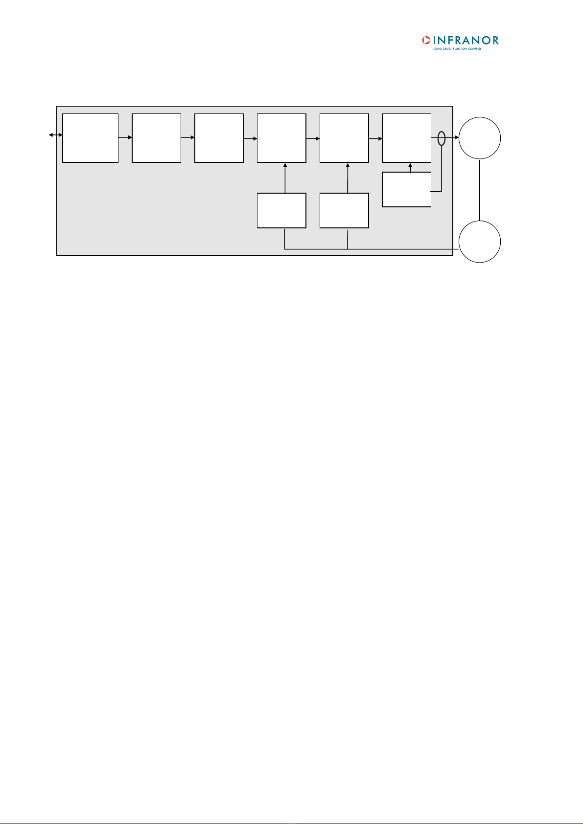
2 - ARCHITECTURE OF A POSITIONER
Electric motor Electric device that transforms electrical energy into a mechanical movement.
This transformation is often made by means of current commutation.
Generally, the movement is a rotation but there are also linear motors.
Motor Electric motor which current commutation is made by mechanical brushes.
Brushless or synchronous
motor
Electric brushless motor. The current commutation is electronically made and
requires a position sensor (resolver, encoder, Hall sensor...).
Resolver Absolute position sensor over one revolution. Resolvers are often used on
brushless motors.
Positioner Electric device for the control of electric motors. It also includes a current
regulator, a speed servo control and, sometimes, a position servo control.
Current loop
Current regulator
Used for the motor current control. The motor torque is generally proportional
to the current amplitude.
Speed loop
Speed regulator
Allows the motor speed control with a speed input command.
Position loop
Position regulator
Allows the motor position control.
Positioner Positioner with position loop and trajectory generator that allows positioning.
Trajectory generator Generates a speed profile (acceleration, step speed, deceleration) that allows
positioning (start position -> arrival position).
Field bus Digital link that allows real time data exchange between various electric
devices. The characteristic of field busses is their high protection and fault
correction level as well as a predictable communication time.
Profibus Fieldbus initially defined by Siemens®. This bus is widely used in automation.
Enabled/disabled
(Servo On/Off)
When a motor is enabled, it is controlled by the positioner and the servo
loops are operating. When it is disabled, its rotation is free and there is no
current in the motor.
Profibus-DP
interface
Sequence
switch
Trajectory
generator
Position
loop
Speed
loop
Current loop
Current
monitor
Speed
monitor
Position
monitor
Motor
Resolver
Chapter 2 - Commissioning 9
SMT-BD1/p - CD1-p - User manual
Chapter 2 - Commissioning
WARNING
During the machine adjustments, some drive connection or parameter setting errors may involve
dangerous axis movements. It is the user's responsibility to take all necessary steps in order to
reduce the risk due to uncontrolled axis movements during the operator's presence in the
concerned area.
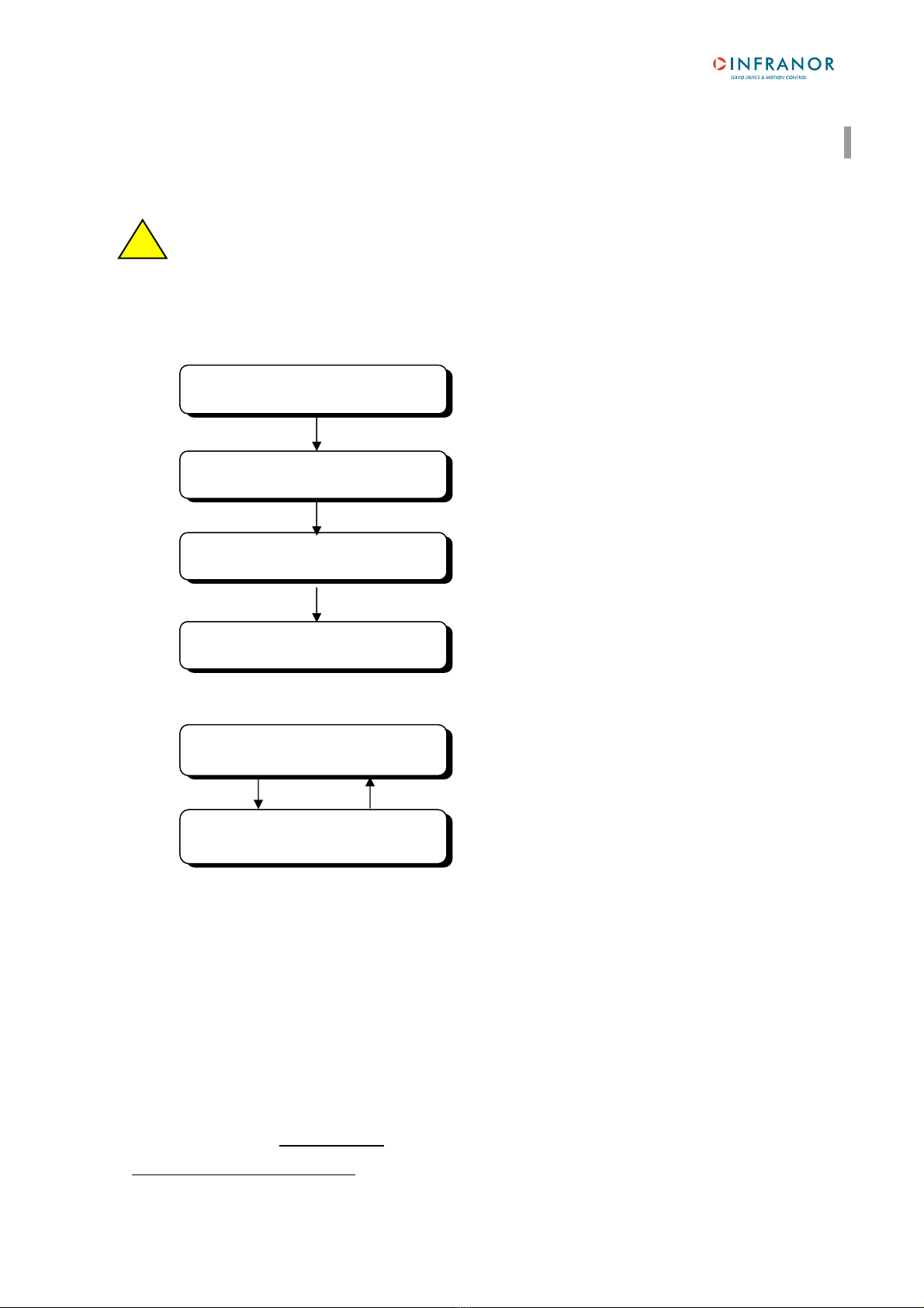
The various stages of a first positioner commissioning are described below:
Both operation stages are:
The positioner parameters are accessible via:
- the serial link and the PC parameter setting software,
- or by the PKW of the PROFIBUS DP.
CAUTION !
Do not make the drive parameter setting by means of both PC software and Profibus at the same time.
INSTALLATION AND USE OF THE PC SOFTWARE
The Visual Drive Setup software is PC compliant under Windows® 1 and allows an easy parameter setting of the
BD1-p and CD1-pamplifiers.
Please see our website www.infranor.fr for downloading the "Visual Amplifier Setup" software.
1Windows®is a registered trade mark of MICROSOFT®CORPORATION
Servo control adjustment
section 4
Motor adjustment
section 3
CONFIGURATION
section 5
PROFIBUS COMMUNICATION
section 8
- Current regulator adjustment.
- Definition of the current limitations and of the I2t protection.
- Adjustment of the motor control parameters.
- Speed limitation definition.
- Rotation direction.
- Adjustment of the servo control parameters according to the
load.
- Definition of the resolution.
- Limit switches.
- Following error.
- Profibus address.
- Communication start between PLC and positioner.
PROGRAMMATION
chapter 3
OPERATION
chapter 4
- Sequences programmation.
- "Operational" phase: sequences execution by Profibus.
!

Chapter 2 - Commissioning
10
SMT-BD1/p - CD1-p - User manual
1 - CHECKING THE POSITIONER HARDWARE CONFIGURATION
The positioner standard configuration for MAVILOR motors equipped with a TAMAGAWA resolver is the following:
SMT-BD1/p positioner:
•Resolver adjustment card P RES: 4 x 12,7 KΩ1%.
•Current loops adjustment.
•Motor thermal probe PTC: Jumper MN.
•Positive control logic: Jumpers E. F. G closed.
•No auxiliary supply: Jumper JK closed and jumper KL open.
•SW1 "OFF" on all switches.
CD1-p positioner:
•Resolver P RES adjustment board: 4 x 12,7 KΩ1%.
For the positioner adjustment to other resolver types, or to another control logic, see Installation manual.
2 - PUTTING INTO OPERATION
For the first positioner powering, see installation manuals (SMT-BD1/p Installation and CD1-p Installation).
The logic voltage (auxiliary supply on the SMT-BD1/p and 24 V on the CD1-p) must be applied to the positioner
before the power voltage.
CAUTION !
When turning off the positioner, wait for at least 5 seconds before turning power on again.
3 - MOTOR ADJUSTMENT
3.1 - Motor parameter setting
Select the positioner and fan types required for the motor used.
Select the positioner current limitation mode. The "Fusing" mode is recommended for the commissioning phases.
In "Fusing" mode, the positioner is disabled when the current limitation threshold is reached.
In "Limiting" mode, the current is only limited at the value defined by the Rated current parameter when the
limitation threshold is reached.
The parameter Max. current defines the maximum current value supplied by the positioner. It can vary between
20 % and 100 % of the positioner current rating. This parameter is defined according to the positioner and motor
specifications.
The Rated current parameter defines the limitation threshold of the RMS current (I2t) supplied by the positioner. It
can vary between 20 % and 50 % of the positioner current rating. This threshold is set according to the positioner
and motor specifications.
Check that the values of the Maximum current and Rated current parameters are complying with motor and
positioner. Otherwise, modify them according to the appropriate motor and positioner specifications.
The Max. speed parameter defines the maximum motor rotation speed. The speed range is between 100 and
10000 rpm and the resolution is 5 rpm. Check that its value is complying with motor and application. Otherwise,
modify it according to the motor and application specifications.
3.2 - Current loops (CD1-p)
When the motor used is not contained in the motor list, the current loops gain values must be defined
according to the supply voltage (230 V or 400 V), to the positioner current rating and to the motor inductance.

Chapter 2 - Commissioning 11
SMT-BD1/p - CD1-p - User manual
3.3 - Adjustment to a new motor
Uncouple the motor from the mechanical load and check that the motor shaft is free and for free rotation
(1 revolution) that is not dangerous for the operator.
Execute the auto-phasing procedure (the positioner must be disabled and the ENABLE signal must be
activated) in order to define the parameters Number of pole pairs, Motor phase and Resolver adjustment.
Please note that during the auto-phasing procedure the motor is automatically enabled and then disabled when
the procedure is over.
If the motor is equipped with a brake, unlock the brake manually before starting the procedure.
The auto-phasing procedure calculates the following parameters:
- The parameter Number of pole pairs defines the number of motor pole pairs.
- The parameter Phases order defines the motor phases order.
- The parameter Resolver offset defines the mechanical shift between both motor and resolver
references.
Calculate the Phase lead parameter from the specific motor parameters (the effects of this parameter are
particularly useful on low inductance motors running at high speeds)
3.4 - I2t protection (BD1p)
Current limitation in Fusing mode
When the amplifier RMS current (I2t) reaches 85 % of the Rated current, the Idyn signal output is activated and
the I2t error display is blinking on the amplifier front panel. If the RMS current (I2t) has not dropped below 85 % of
the Rated current within 1 second, the I2t fault is released and the amplifier is disabled (otherwise, the Idyn signal
and the blinking I2t error display are both cancelled).
When the amplifier RMS current (I2t) reaches the Rated current value, the I2t protection limits the amplifier
current at this value.
The amplifier current limitation diagram in an extreme case (motor overload or locked shaft) is shown below.
The maximum current duration before the release of the Idyn signal depends on the value of the Rated current
and Maximum current parameters. This value is calculated as follows:
T dyn (second) = t1 - t0 = 3.3 x [ Rated current (%) / Maximum current (%) ]2
The maximum current duration before the limitation at the rated current also depends on the value of the Rated
current and Maximum current parameters. This value is calculated as follows:
T max (second) = t2 - t0 = 4 x [ Rated current (%) / Maximum current (%) ]2
NOTE 1
The above formulas are valid as long as the Maximum current / Rated current ratio is higher than 3/2. When
the Maximum current / Rated current ratio is close to 1, the calculated values of Tdyn and Tmax are quite
below the real values. For example when Maximum current / Rated current = 1.2, the measured Tdyn = 3.4
seconds and the measured Tmax = 4.4 seconds. When the Maximum current / Rated current ratio is equal to
1, the I²t protection is no more disabling the amplifier but the current is limited at the Rated current value.
t0 t1 t2 t3
Amplifier current
Maximum current.
Rated current
1 second
t1 = Idyn signal activation
t2 =Current limitation
t3 = I²t fault
time

Chapter 2 - Commissioning
12
SMT-BD1/p - CD1-p - User manual
NOTE 2
The amplifier I²t signal can be displayed on the digitizing oscilloscope by selecting the "I²t" signal in the
“ Channel ” menu. The I²t signal threshold values according to the I²t protection mode described above are
calculated in the following way:
Idyn signal activation threshold (%) = [Rated current (%)]2/ 70
Current limitation threshold (%) = [Rated current (%)]2/ 50
The corresponding amplifier RMS current value can be calculated according to following formula :
Amplifier RMS current (%) = [I²t signal value (%) x 50]1/2
Current limitation in Limiting mode
When the amplifier RMS current (I2t) reaches 85 % of the Rated current, the Idyn signal output is activated and
the I2t error display is blinking on the amplifier front panel. When the RMS current (I2t) drops below 85 % of the
Rated current, the Idyn signal and the blinking I2t error display are both cancelled.
When the amplifier RMS current (I2t) reaches the Rated current value, the I2t protection limits the positionner
current at this value.
The amplifier current limitation diagram in an extreme case (motor overload or locked shaft) is shown below.
The maximum current duration before the release of the Idyn signal output (t1 - t0) and before limitation at the
rated current (t2 - t0) is calculated the same way as for the Fusing mode.
The I²t signal threshold values and the amplifier RMS current value on the digitizing oscilloscope, are also
calculated the same way as for the Fusing mode.
Maximum current
Rated current
Amplifier current
t1 t2t0
time
t1 = Idyn signal
t2 = Current limitation
InFusing mode, the amplifier Rated current value must be adjusted lower or equal to the
Maximum authorized rated current of the amplifier.
!
In Limiting mode, the amplifier Rated current value must be adjusted lower or equal to the
Maximum authorized continuous current of the amplifier.
!

Chapter 2 - Commissioning 13
SMT-BD1/p - CD1-p - User manual
3.5 - I2t protection (CD1p)
Current limitation in Fusing mode
If the RMS current as not dropped below 85 % of the Rated current after 1 second, the I2t fault is released and
the amplifier disabled.
When the amplifier RMS current (I2t) reaches the Rated current value, the I2t protection limits the amplifier
current at this value.
The amplifier current limitation diagram in an extreme case (motor overloaded or shaft locked) is shown below:
t0 t2 t3
Rated current
Maximum current
Amplifier current
t2 = current limitation
t3 = I2t fault
Time
The maximum current duration before limitation at the rated current is depending on the value of the Rated
current and Maximum current parameters.
Tmax (second) = (t2- t0) = 4 x [Rated current (A)]2/ [Maximum current (A)]2
The current limitation duration before the release of the protection is depending on the value of the Rated current
and Maximum current parameters:
Tlim (second) = (t3- t2) = 1 - 0.7 x [Rated current (A)]2/ [Maximum current (A)]2
NOTE
- These formula are correct for a Maximum current / Rated current ratio > 1.5.
- When the Maximum current / Rated current ratio = 1, there is no interruption and the current is maintained
at the rated current value.
- The I2t signal can be displayed by means of the digitizing oscilloscope available in the Visual Drive Setup
software.
Rated current (%) = 100 x Rated current (A) / Amplifier current rating (A)
Current limitation threshold (%) = [Rated current (%)]2/ 50
Amplifier RMS current (Arms) = [(I2t signal value (%)) x 50]1/2 x Amplifier current rating (A) / 100
Current limitation in Limiting mode
When the amplifier RMS current (I2t) reaches the Rated current value, the I2t protection limits the amplifier
current at this value.
The amplifier current limitation diagram is shown below.
t0 t2
Rated current
Maximum current
Amplifier current
t2 = current limitation
Time
The maximum current duration before limitation at the rated current (t2 - t0) is calculated the same way as for the
Fusing mode.

Chapter 2 - Commissioning
14
SMT-BD1/p - CD1-p - User manual
3.6 - Rotation/counting direction
This possibility defines the position counting direction with regard to the motor rotation direction. For the encoder
position output, the counting direction remains unchanged with regard to the motor rotation direction.
On Mavilor motors, in normal rotation, the position is incrementing in the motor CW rotation direction. In reverse
rotation, the position is incrementing in the motor CCW rotation direction.
3.7 - Maximum application speed
The parameter Max. speed defines the maximum speed with which the positioner can control the motor. This
parameter must be:
- lower or equal to the max. motor speed,
- approximately 20 % higher than the maximum motor rotation speed in the application. This margin allows a
speed overshooting and avoids a position loop saturation (which would involve a position following error). This
margin can be smaller when the loop bandwidth is high and the accelerations low.
3.8 - Thermal sensor configuration on the CD1-p positioner
There are 2 possible sensor types that can be software configurated:
PTC sensor: the triggering will occur at a value of about 3.3 kOhms of the thermal sensor resistor, that is 140°C.
NTC sensor: the triggering will occur at a value of about 3.3 kOhms of the thermal sensor resistor, that is 140°C.
4 - SERVO CONTROL ADJUSTMENT
4.1 - Regulator parameters
WARNING
The auto-tuning procedure should be executed by the PC in control mode and at standstill. If the
auto-tuning procedure must be executed with the drive controlled by the analog command input
CV, the value of the input command MUST be 0 Volt. It is the user's responsibility to take all
necessary steps in order to reduce the risk due to uncontrolled axis movements during the auto-
tuning procedure.
The auto-tuning procedure identifies the motor and load specifications and calculates the regulator gain
parameters. During the procedure, the operator can select 1 bandwidth (Low , Medium and High) and 1 filter
(standard, antiresonance and high stiffness – the last filter is only available on the CD1-p positioner). These
values correspond to the cut-off frequency for a 45° speed loop phase shift.
The auto-tuning can be executed with disabled or enabled motor (i.e. vertical load), but the ENABLE signal must
always be activated.
If the motor is equipped with a brake, unlock the brake manually before starting the procedure.
Check for free motor shaft rotation over one revolution, that is not dangerous for operator and
machine before starting the auto-tuning with filter = standard.
After the auto-tuning procedure, check that the motor correctly runs in both directions.
Check the response for a small movement without IDC saturation.
In case of loud noise in the motor at standstill and when running, check the rigidity of the transmission between
motor and load (backlashes and elasticities in gears and couplings).
If necessary, renew the auto-tuning procedure by selecting a lower bandwidth. If the problem remains, renew the
auto-tuning procedure by activating the antiresonance filter.
Adjust more accurately the loop response stability by adjusting the stability gain.
!
!

Chapter 2 - Commissioning 15
SMT-BD1/p - CD1-p - User manual
4.2 - Regulator adjustment with vertical load
In the case of an axis with unbalanced load (constant torque due to a vertical load), proceed as follows:
Select the current "Limiting" mode.
Initialize the speed loop gains corresponding to the unloaded motor (run the auto-tuning procedure with the motor
uncoupled from its mechanical load).
Couple the motor with the load. If possible, make a speed control; otherwise, close the position loop with a stable
gain.
Move the shaft by means of the speed input command until a maintaining position where one
motor revolution is not dangerous for operator and machine (far enough from the mechanical
limit stops).
Run the auto-tuning function with motor at standstill. If the motor shaft is moving, the auto-tuning has not been
accepted by the positioner.
4.3 - Enabling
The enabling can be made:
- by Profibus (see operation diagram for the enabling procedure in chapter 4, section 2.1) or
- by the PC parameter setting software.
4.4 - Brake control
•The SMT-BD1/p positioner is equipped with a brake control signal.
This brake control signal is low powered and cannot directly control the brake. The BMM 05 AF single-axis
rack is therefore equipped with a power relay that allows the brake control (the multiaxes rack is not equipped
with this relay).
•The CD1-p positioner is equipped with a brake control (made by transistor).
•The brake control is activated (relay open) or disabled (relay closed) according to the positioner status
(disabled or enabled).
4.5 - Limit switches adjustment
The limit switch inputs are inputs for a proximity sensor that stops the motor with maximum deceleration. When
both limit switches are correctly placed on the motor stroke, they are a protection for the machine in case of
incorrect movement.
The limit switches are only defined according to the physical motor rotation. They are not depending on the
selected "rotation/counting direction".
On Mavilor motors, if the option "rotation/counting direction" is normal, the FC+ input must be wired in the positive
motor counting direction.
For checking the limit switches:
- move the motor in one direction,
- activate the limit switch which is located in the movement direction (artificially, if necessary),
- check that the motor is stopping,
- if the motor does not stop, the limit switches are reversed wired.
Check also in the opposite direction.
Notes
- The motor is stopped with maximum deceleration by a limit switch.
- Reminder: The limit switches are wired as "normally closed".
!

Chapter 2 - Commissioning
16
SMT-BD1/p - CD1-p - User manual
5 - CONFIGURATION
5.1 - General parameters
Speed profile: trapezoidal or S-curve.
Brake on delay: defines the time between the brake enabling and the positioner disabling.
- brake activation (relay open),
- delay time,
- positioner disabling.
Brake off delay: defines the time between the positioner enabling and the brake disabling:
- positioner enabling,
- delay time,
- brake disabling (relay closed).
Minimum SEQ pulse (on CD1-p and from firmware version 507.18 on BD1/p): When activated, this function
defines the minimum duration of the SEQ output.
Configuration: bit 12 of PNU 742 (positioner configuration).
InPos window (on CD1-p and from firmware version 507.18 on BD1/p): When activated, this function defines
the position window in which the InPos output is activated (only for a positioning). This window is equal to the
arrival position +/- the programmed value.
Digital CAM (on CD1-p and from firmware version 507.18 on BD1/p): When activated, this function activates
the logic output OUT1 (bit 0 of the virtual outputs) when the motor passes an area defined by positions P1 and P2.
Configuration: bit 14 of PNU 742 (positioner configuration).
Position value (32 bits): PNU 758 and PNU 759.
5.2 - Manual motion parameters
There are 2 types of manual motion:
- basic positioning: moving of the motor until a given position directly by the operator.
- jog: continuous movement when the jog signal is activated (JOG+ for a movement in the positive
direction and JOG- for a movement in the negative direction).
The motion profile parameters are:
- "motion speed",
- "acceleration time",
- "deceleration time"
These three parameters can be independently adjusted for a Jog or a Positioning.
OUT1 output
Position P1 Position P2
Motor position

Chapter 2 - Commissioning 17
SMT-BD1/p - CD1-p - User manual
The parameters "acceleration time" and "deceleration time" define the time with regard to the max. speed (defined
by the parameter "Speed limitation"). When the motion speed is lower than the maximum speed, the trajectory
acceleration and deceleration times are proportionally smaller.
NOTE: Concerns only the positioning sequences.
5.3 - Scale parameters
Position resolution: defines the position resolution for one motor revolution according to the number of decimals
and the unit required. The adjustment range is between 16 and 65536 ppr.
Decimal number: Factor of 10 for the position resolution (1, 2 or 3).
Unit: Defines the position unit (maximum 4 characters).
Example: For a resolution of 4 mm/motor rev., if the number of decimals is 3, the parameters will be:
Resolution = 4000, Decimal number = 3, Unit = mm.
Following error threshold: defines the following error triggering threshold.
It is important to correctly adjust this value in order to get a good protection.
It can be adjusted like follows:
1 - Make the motor rotate with the required operation cycles and measure the maximum following error threshold:
- either by means of the oscilloscope of the parameter setting software,
- or by reducing the following error threshold value until the fault is triggered,
2 - Then set the following error threshold at this value plus a margin of 30 to 50 %.
Example: Adjustment of the following error threshold on an axis with:
Position resolution = 5000.
Maximum following error measured by oscilloscope = 0,05 V.
The following error value is: 0,05 / 10 x 32767 = 164.
The threshold is set at 246 (margin = 50 %).
Note: In the PC parameter setting software, if the number of decimals is set at 3, the value that must be entered is
0,246.
Deadband: Defines the deadband for the position controller. When this parameter is set at 0, the deadband is
disabled.
CLR input enable: When activated (box ticked off), this function allows the use of the INDEX input for resetting
the position counter: the active/inactive transition uploads the value of the Clear position parameter in the
position counter.
Reset counter/Modulo: This function resets the position counter as soon as it has reached the predefined
position. If the value is set at 0, this function is disabled.
Forward: When the Reset counter/Modulo function is activated and if the Forward function is selected, the
motor only runs in the positive direction for an absolute motion lower than the value defined by the Reset Counter
parameter.
When the Reset counter/Modulo function is activated and if the Forward function is not selected, for an absolute
motion lower than the value defined by the Reset Counter parameter, the motor follows the shortest way
(whichever the motor rotation direction).
Max. speed
Acceleration ramp Deceleration ramp
Motion speed
parameter

Chapter 2 - Commissioning
18
SMT-BD1/p - CD1-p - User manual
Software limit switches + and - (CD1p and from firmware version 507.18 on BD1p): This function is only
active if a "Home" sequence has been executed before. When the motor shaft passes the limit position
programmed, it is stopped with a controlled braking. The deceleration value is provided by the parameter "Jog
deceleration time".
Configuration : Bit 0 of PNU 742 for the positive direction, and bit 1 of PNU 742 for the negative direction.
5.4 - Encoder output parameters (SMT-BD1/p only)
The parameter Encoder resolution defines the encoder resolution on channels A and B (X2 connector) of the
encoder position output for one motor shaft revolution. Binary and decimal values are both accepted. The
maximum encoder resolution per revolution is limited by the motor rotation speed as shown in the table below.
Max. possible speed (rpm) 900 3600 10000
Max. encoder resolution 8192 4096 1024
The parameter Number of zero pulse defines the number of marker pulses on channel Z for one motor shaft
revolution. The adjustment range is between 1 and 16.
The parameter Zero pulse origin shift defines the shift between the first marker pulse on channel Z and the
resolver reference position. The adjustment range is between 0 and 32 767. The value 32 767 corresponds to one
motor shaft revolution.
The parameter Zero pulse width defines the marker pulses width on channel Z in ppr. The adjustment range is
between 8 and 32 767. The value 32 767 corresponds to one motor shaft revolution.
Caution
The encoder output is not available on the CD1-p series positioners, eventhough these parameters are existing.
6 - PROFIBUS ADDRESS
Each positioner of the network is identified by one single address (1 to 125). The positioner is delivered with the
default address 126 which is not an operational address. This address must be modified before putting the bus
into operation.
The SMT-BD1/p or CD1-p address can be modified:
- by the serial RS-232 link (PC parameter setting software). The new address must be saved in the EEPROM
and the positioner must be switched on again in order to get the new address operational;
- or by a Profibus class 2 master device.The address modification is only possible when the bus is not
running. In this case, the address will be automatically saved in the positioner EEPROM and will be
operational at the bus starting.
The identity number of the SMT-BD1/p and CD1-p positioners under Profibus is 0x00C7.
7 - PARAMETERS SAVING
When all adjustments are made, the parameters must be saved in the EEPROM ( with disabled positioner).
Chapter 2 - Commissioning 19
SMT-BD1/p - CD1-p - User manual
8 - PROFIBUS COMMUNICATION
The Profibus communication is a master-slave communication. The INFRANOR®positioner is a slave positioner
and the only important parameter to be defined for the communication is the amplifier address on the bus.
All other parameters (communication speed, configuration, parameters) are defined in the PLC (master) and will
be automatically sent to the positioner:
- the available communication speeds are: 9,6 KB, 19,2 KB, 93,72 KB, 187,5 KB, 500 KB, 1,5 MB, 3 MB,
6 MB, 12 MB and will be automatically detected by the positioner.
- the configuration used will be sent to the slave at the bus starting. The available configurations are PPO1,
PPO2, PPO3 or PPO4,
- default parameter setting: not used by the positioner.
These various possibilities are pre-defined in a GSD file proper to each product range running with Profibus. The
file for the INFRANOR®positioner is INFR00C7.GSD and is is available for download from the website
www.infranor.fr.
When defining the network on the master, please:
- import the slave GSD file if this has not yet been done,
- create a network with the master,
- connect a slave on the network with the same address as defined in the slave.
Note: When the communication is established, the green "RUN" LED lights up.
8.1 - PPO message
In the PROFIBUS-DP communication model, a slave module consists of a certain number of inputs-outputs or
inputs-outputs modules. Each module is defined by an identifier. This identifier contains information on the module
direction (input, output or input-output), on the number of bytes or words and on the module consistancy. The
configuration is defined in the DP master and is sent to the slave by means of the Chk_Cfg function at the bus
starting. The slave checks if this configuration is compatible and configures itself before switching on to data
exchange mode (Data_Exchange).
There is also a communication mechanism more complicated than a basic inputs/outputs identifier: the PPO
messages. These messages are often used in the "device profiles".
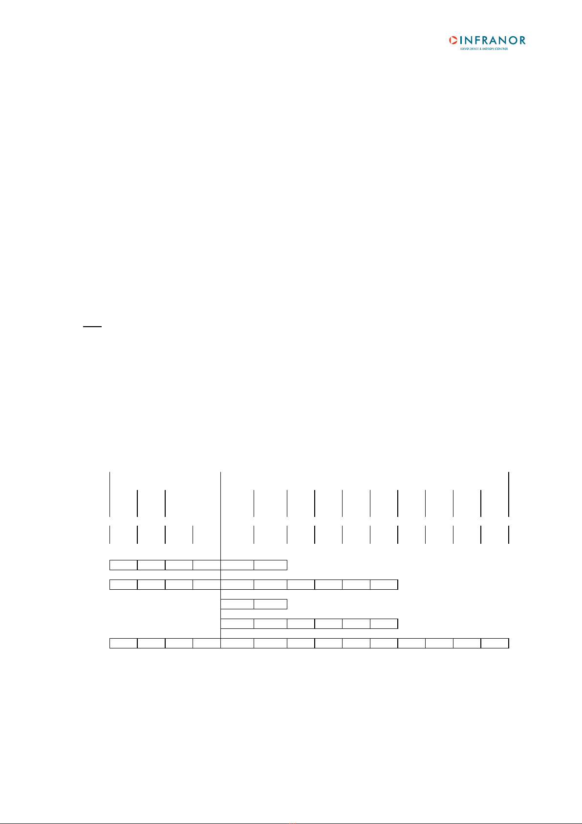
There are 5 PPO types defined for the various device profiles under Profibus:
PKW PZD
PKE IND PWE PZD1 PZD2 PZD PZD PZD PZD PZD PZD PZD PZD
STW HSW 3 4 5 6 7 8 9 10
ZSWHIW
1st
Word
2nd
Word
3rd
Word
4th
Word
1st
Word
2nd
Word
3rd
Word
4th
Word
5th
Word
6th
Word
7th
Word
8th
Word
9th
Word
10th
Word
PPO1
PPO2
PPO3
PPO4
PPO5
PKW Parameter setting data.
PKE Parameter code (bytes 1 to 2).
IND Index (byte 3).
PWE Parameter value (bytes 5 to 8).
PZD Process data (cyclically transferred).
STW Control.
ZSW Status.
HSW Input command.
HIW Information feedback.

Chapter 2 - Commissioning
20
SMT-BD1/p - CD1-p - User manual
A PPO message can contain 1 or 2 modules called PKW and PZD.
Each module (PKW or PZD) is defined as input-output and is consistant over the whole module length.
The communication is made by the reading or writing of PPO messages (the PKW and PZD modules are input
and output at the same time). The master sends a message by a PPO-write and receives a message by PPO-
read. The PPO-write and PPO-read messages are cyclically transferred by the PROFIBUS DP Data_Exchange
function.
The modules are consistant. This means that the different words of a same message must be transmitted or
received in one single transfer. So, it is not possible to directly read or write in the PLC inputs/outputs area;
special functions must be used for the data reading or writing.
Example: In the STEP7®software, the SFC14 and SFC15 functions are used for the reading and writing of the
consistant modules.
In the above example, the SFC14 and SFC15 functions are used for reading or writing the PZD module (PPO2
case). The W#16#108 address is the physical module address on the network that is obtained when connecting
the slave to the network. This address is the same for the reading (SFC14) and writing (SFC15) because the
module is an input-output module. The result of the reading will be transferred in the memory area at the address
40 by SFC14 (12 bytes). The SFC15 function will transfer the data at the address 20 (12 bytes) on the bus.
The PKW will require a SFC14 (reading) and a SFC15 (writing) and the PZD will require a SFC14 and a SFC15.
PKW is by definition used for the positioner parameter setting and PZD is used for its operational control.
The INFRANOR®positioner uses the PPO messages mechanism for communicating by Profibus-DP.
The SMT-BD1/p and CD1-p positioners accept the PPO1, PPO2, PPO3 or PPO4 types.
SFC15
EN ENO
LADDR
RECORD
RET_VALW#16#108 MW101
P#M 20.0 BYTE 12
SFC14
EN ENO
LADDR
RECORD
RET_VAL
W#16#108 MW100
P#M 40.0 BYTE 12
This manual suits for next models
1
Table of contents


