PowerLink CM
Smart Communications, PowerLink CM Product Information
C53000-X6040-C256-2 Edition Sept. 2021 1
Read and understand these instructions and the relevant manual before installing,
operating, or maintaining the device. For available software and complete documentation for
PowerLink CM see:
Siemens Industry Online Information platform SIOS
Further Support
If special problems arise, or further information are required, please contact your Siemens
representative. Our Customer Support Center provides a 24-hour service.
Siemens AG
Smart Infrastructure – Digital Grid
Customer Support Center
● Phone: +49 911 2155 4466
Disclaimer of Liability
Although we have carefully checked the contents of this publication for conformity with the
hardware and software described, we cannot guarantee complete conformity since errors
cannot be excluded.
The information provided in this manual is checked at regular intervals and any corrections
that might become necessary are included in the next releases. Any suggestions for
improvement are welcome.
Copyright
Copyright © Siemens AG 2021 – All Rights Reserved
The reproduction, transmission or use of this document or its contents is not permitted
without express written authority. Offenders will be liable for damages. All rights, including
rights created by patent grant or registration of a utility model or design, are reserved.
OpenSSL
This product includes software developed by the OpenSSL Project for use in OpenSSL
Toolkit (http://www.openssl.org/).
This product includes software written by Tim Hudson (tjh@cryptsoft.com).
This
product
includes
c
ryptographic
software
wri
tten
by
Eri
c
Young
(
[email protected]).
Notes on Safety
This document contains notes that must be adhered to ensure personal safety and to avoid
damage to property during commissioning and use.
However, it does not constitute a complete description of all safety measures required for
installation, service, and maintenance of the device. Details are to be taken from the device
manual; those are mandatory. Keep it safe for later usage.
Warning: Danger of severe personal injury or substantial damage to property
Hazardous voltages may occur in devices and modules during operation. Always
observe the instructions
given in “Qualified Electrical Engineering Personnel” below.
Qualified Electrical Engineering Personnel
Qualified electrical engineering personnel must have up to date technical qualifications
as electrical technicians. Only these persons may commission, use, maintain,
decommission and dispose of the device according to the
state-of-the-art standards of
neering in the high voltage power line environment.
Laser radiation! Danger of eye injury
This device may contain a class 1 laser.
Do not look directly into the beam.
Danger of damage due to static electrical charges
printed circuit boards of numerical relays contain CMOS circuits. These shall not
be withdrawn or inserted under live conditions! The modules must be so handled that
any possibility of damage due to static electrical charges is excluded.
ry handling of individual modules, the recommendations relating to
the handling of electrostatically endangered components (EEC) must be observed.
In installed conditions, the modules are in no danger.
Use as Prescribed
The device may only be used for such applications as set out in the user instructions, and
only in combination with equipment recommended and approved by Siemens.
Correct and safe operation of the product requires adequate transportation, storage,
installation and mounting in a control cabinet, as well as appropriate use and maintenance.
Only qualified electrical engineering personnel may install, set up, commission, attach
communication cables, power supply lines and ground to the device.
Check and follow the electrical operating conditions, mechanics, and climatic max. ambient
conditions for safe operation. Connect and operate the device only in conformance with the
values as specified in the ‘Technical Data’ below.
Commissioning must be carried out in accordance with good engineering practice and
under consideration of local installation rules and laws (also applicable and obligatory for
cabinet internal wiring).
Fuses may be required on all phases in the electrical installation, depending on local
installation conditions and requirements.
During operation of the equipment, it is unavoidable that certain parts will carry dangerous
voltages. Severe injury or damage to property can occur if the appropriate measures during
use are not taken:
•Make sure, that the equipment is properly connected to ground at all times and
mechanically fixed in the rack. The device is connected through a coupling unit to the
HV line. A permanent ground connection is an essential precondition to safeguard the
user against any high voltages from the HV line.
•Degree of protection by enclosure IP20.
•Device may only be operated in a dry location within a temperature range of
-10 to +55 degree Celsius.
•This is a Class A device. It is intended to be operated in an industrial environment only.
It may cause harmful interference if operated in residential/light industry environment.
•Hazardous voltages can be present on all components when the device is connected
to a power source. Before opening the device, makes sure all power sources are
disconnected or switched off. Even after the power supply has been disconnected,
hazardous voltages can still be present within the device (capacitor storage).
•The limit values indicated in the manual must not be exceeded; that also applies to
testing and commissioning.
Statement of Conformity
The product is in conformity with the regulat
ions of the following European Directives:
•EMC Directive 2014/30/EU
•Low Voltage Directive 2014/35/EU
•RoHS Directive 2011/65/EU
Used Symbols
Caution, hazard. The documentation
must be observed.
Protection class I / protective
earthing
CE conformity
Hazardous voltage
Qualified Electrical Engineering
Personnel
Note
Distributor statement according to WEEE-Guideline 2012/19/EU
Do not throw the device in the household trash! Please dispose of the device
according to the guidelines regarding electronic waste in your country.
Application
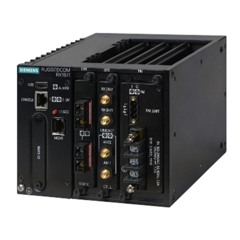
PowerLink CM is a condition monitoring system for high voltage lines.
Unpacking a Device
•Check the package for external transport damage. A damaged packing may indicate
that the device inside is also damaged.
•Unpack the device carefully; do not use force.
•Visually check the device to ensure that it is in perfect mechanical condition.
•Return a damaged device to the manufacturer or dispose it correctly. A defect device
may not either be used or repaired by the user.
Before commissioning the device, leave it in the final operation room for at least
hours. This allows it to reach room temperature and to prevent dampness and
Repacking a Device
•If you store devices after incoming inspection, pack them in suitable storage
packaging.
•If devices are to be transported, pack them in transport packing.
•Put the accessories supplied in the packing with the device.
Storing a Device
•Only store devices on which you have carried out an incoming inspection, thus
ensuring that the warranty remains valid.
•The relative humidity must be at a level where condense water and ice are prevented
from forming.
•If the device has been in storage for more than 2 years, connect it to the primary
voltage source, and operate it for 1 to 2 days. This will cause the electrolytic capacitors
to form on the printed circuit board assemblies again.
•When the device is reshipped ensure that the transport requirements for the selected
means of transport are met. The outer package alone is not adequate for transport
purposes.
Mounting
The device is designed for horizontal mounting in a cabinet or rack. Min. distance between
two PowerLink CM devices is one unit of height (= 1.75 inches or 44.45 mm). The climatic
conditions have to be within the specified values (see technical data). Consider the weight
and position of the device to avoid personal injuries.
Commissioning
Before making any connections, ground the equipment and the grounding
terminal.
•Connection of the Supply Voltage: The AC supply voltage is connected to the terminals
PE-N-L1 (Protective Earth, Neutral, Line). In case of DC voltage, the (-) is connected to
the N and (+) to the L1 terminal. The terminals are covered. The supply voltage
connected must be within the specified limit values (see technical data). These values
indicated in the manual must not be exceeded at any time.
•Make sure that all front and back covers of the device are remounted upon completion
of the installation.
•Turn on the Supply Voltage: switch S1 located on DMB board enables/disables the
secondary voltages of the power supply.
•Down position: Off mode; LED "i" (red) lights up on the PSPA2 power supply unit(s).
Up position: On mode; LEDs +48V/-48V (green) lights up on the PSPA2 power supply
unit(s).
•After system startup the LEDs on DMB board will light up green.
