NEXCOBOT NEIO Series User manual

NexCOBOT Co., Ltd.
IoT Automation Solutions Business Group
EtherCAT Slave Module
NEIO Series
User Manual
NexCOBOT Co., Ltd.
Published June 2020 www.nexcobot.com

Copyright © 2019 NexCOBOT Co., Ltd. All Rights Reserved. ii NEIO Series User Manual
Contents
Contents
Preface
Copyright .............................................................................................. v
Disclaimer............................................................................................... v
Acknowledgements ................................................................................ v
Regulatory Compliance Statements......................................................... v
Declaration of Conformity....................................................................... v
RoHS Compliance .................................................................................. vi
Warranty and RMA ................................................................................vii
Safety Information ................................................................................. ix
Installation Recommendations................................................................ ix
Safety Precautions................................................................................... x
Technical Support and Assistance........................................................... xi
Conventions Used in this Manual........................................................... xi
Global Service Contact Information........................................................xii
Chapter 1: Product Introduction
1.1 Overview .........................................................................................1
1.2 Product Appearance ........................................................................2
1.3 Key Features ....................................................................................3
1.4 Model Designation...........................................................................4
1.5 General Specifications......................................................................6
1.6 Mechanical Dimensions....................................................................7
1.7 Hardware Installation Guidelines ......................................................8
1.7.1 Wiring Instructions ....................................................................8
1.7.2 Mounting Instructions .............................................................11
Chapter 2: Digital Input Module
2.1 NEIO-B1101 32-ch Digital Input EtherCAT Slave Module (PNP) .......13
2.1.1 Introduction ............................................................................13
2.1.2 Wiring Diagram.......................................................................13
2.1.3 Pin Assignments ......................................................................14
2.1.4 LED Indicators..........................................................................15
2.1.5 Hardware Specifications...........................................................15
2.1.6 Object Dictionary.....................................................................16
2.2 NEIO-B1102 32-ch Digital Input EtherCAT Slave Module
(PNP/NPN)......................................................................................17
2.2.1 Introduction ............................................................................17
2.2.2 Wiring Diagram.......................................................................17
2.2.3 Pin Assignments ......................................................................18
2.2.4 LED Indicators..........................................................................19
2.2.5 Hardware Specifications...........................................................19
2.2.6 Object Dictionary.....................................................................20
Chapter 3: Digital Output Module
3.1 NEIO-B1201 32-ch Digital Output EtherCAT Slave Module (NPN)....21
3.1.1 Introduction ............................................................................21
3.1.2 Wiring Diagram.......................................................................21
3.1.3 Pin Assignments ......................................................................22
3.1.4 LED Indicators..........................................................................23
3.1.5 Hardware Specifications...........................................................23
3.1.6 Object Dictionary.....................................................................24

Copyright © 2019 NexCOBOT Co., Ltd. All Rights Reserved. iii NEIO Series User Manual
Contents
3.2 NEIO-B1202 32-ch Digital Output EtherCAT Slave Module (PNP) ....25
3.2.1 Introduction ............................................................................25
3.2.2 Wiring Diagram.......................................................................25
3.2.3 Pin Assignments ......................................................................26
3.2.4 LED Indicators..........................................................................27
3.2.5 Hardware Specifications...........................................................27
3.2.6 Object Dictionary.....................................................................28
Chapter 4: Mixed Digital Input/Output Module
4.1 NEIO-B1811 32-ch Digital Input/Output EtherCAT Slave Module ....29
4.1.1 Introduction ............................................................................29
4.1.2 Wiring Diagrams .....................................................................29
4.1.3 Pin Assignments ......................................................................30
4.1.4 LED Indicators..........................................................................31
4.1.5 Hardware Specifications...........................................................32
4.1.5 Hardware Specifications Cont..................................................32
4.1.6 Object Dictionary.....................................................................32
4.2 NEIO-B1812 32-ch Digital Input/Output EtherCAT Slave Module ....33
4.2.1 Introduction ............................................................................33
4.2.2 Wiring Diagrams .....................................................................33
4.2.3 Pin Assignments ......................................................................34
4.2.4 LED Indicators..........................................................................35
4.2.5 Hardware Specifications...........................................................36
4.2.5 Hardware Specifications Cont..................................................36
4.2.6 Object Dictionary.....................................................................36
Chapter 5: Communication Module
5.1 NEIO-B1603 4-ch COM Port EtherCAT Slave Module......................37
5.1.1 Introduction ............................................................................37
5.1.2 Wiring Diagram for RS-485 .....................................................37
5.1.3 Pin Assignments ......................................................................38
5.1.4 LED Indicators..........................................................................39
5.1.5 Hardware Specifications...........................................................39
5.1.6 Operation Principle..................................................................40
5.1.6 Object Dictionary.....................................................................46
5.1.6.1 PDO Mapping ...................................................................46
5.1.6.2 Object Data Type...............................................................47
5.1.6.3 Object Description.............................................................47
5.1.7 Troubleshooting.......................................................................68
Chapter 6: Mixed Analog Input/Output Module
6.1 NEIO-B1841 8-ch AI, 2-ch AO, 16-ch DI/O EtherCAT Slave Module
(Single-ended)................................................................................69
6.1.1 Introduction ............................................................................69
6.1.2 Wiring Diagrams .....................................................................69
6.1.2 Wiring Diagrams Cont.............................................................70
6.1.3 Pin Assignments ......................................................................71
6.1.4 LED Indicators..........................................................................72
6.1.5 Hardware Specifications...........................................................73
6.1.5 Hardware Specifications Cont..................................................73
6.1.5 Hardware Specifications Cont..................................................74
6.1.6 Operation Principle..................................................................75
6.1.7 Object Dictionary.....................................................................83
6.1.7.1 PDO Mapping ...................................................................83
6.1.7.2 Object Data Type...............................................................84
6.1.7.3 Object Description.............................................................84
Chapter 7: Mixed Analog Input/Output Module
7.1 NEIO-B1842 4-ch AI, 2-ch AO, 16-ch DI/O EtherCAT Slave Module
(Differential)...................................................................................95
7.1.1 Introduction ............................................................................95
7.1.2 Wiring Diagrams .....................................................................95
7.1.2 Wiring Diagrams Cont.............................................................96
7.1.3 Pin Assignments ......................................................................97

Copyright © 2019 NexCOBOT Co., Ltd. All Rights Reserved. iv NEIO Series User Manual
Contents
7.1.4 LED Indicators..........................................................................98
7.1.5 Hardware Specifications...........................................................99
7.1.5 Hardware Specifications Cont..................................................99
7.1.5 Hardware Specifications Cont................................................100
7.1.6 Operation Principle................................................................101
7.1.7 Object Dictionary...................................................................110
7.1.7.1 PDO Mapping .................................................................110
7.1.7.2 Object Data Type.............................................................111
7.1.7.3 Object Description...........................................................111
Chapter 8: EtherCAT Communication
8.1 ESI and ENI File ............................................................................123
8.2 EtherCAT State Machine ..............................................................124
8.3 NEIO Configuration......................................................................125
8.3.1 Operation with TwinCAT........................................................125
8.3.2 Operation with NexECM EtherCAT Configuration Tool...........128

Copyright © 2019 NexCOBOT Co., Ltd. All Rights Reserved. vNEIO Series User Manual
Preface
PrefaCe
Copyright
This publication, including all photographs, illustrations and software, is
protected under international copyright laws, with all rights reserved. No
part of this manual may be reproduced, copied, translated or transmitted in
any form or by any means without the prior written consent from Nexcobot
Co., Ltd.
Disclaimer
The information in this document is subject to change without prior notice
and does not represent commitment from Nexcobot Co., Ltd. However, users
may update their knowledge of any product in use by constantly checking its
manual posted on our website: http://www.nexcobot.com. NexCOBOT shall
not be liable for direct, indirect, special, incidental, or consequential damages
arising out of the use of any product, nor for any infringements upon the rights
of third parties, which may result from such use. Any implied warranties of
merchantability or fitness for any particular purpose is also disclaimed.
Acknowledgements
The NEIO series is a trademark of Nexcobot Co., Ltd. All other product names
mentioned herein are registered trademarks of their respective owners.
Regulatory Compliance Statements
This section provides the FCC compliance statement for Class B devices and
describes how to keep the system CE compliant.
Declaration of Conformity
FCC
This equipment has been tested and verified to comply with the limits for
a Class B digital device, pursuant to Part 15 of FCC Rules. These limits are
designed to provide reasonable protection against harmful interference when
the equipment is operated in a commercial environment. This equipment
generates, uses, and can radiate radio frequency energy and, if not installed
and used in accordance with the instructions, may cause harmful interference
to radio communications. Operation of this equipment in a residential area
(domestic environment) is likely to cause harmful interference, in which
case the user will be required to correct the interference (take adequate
measures) at their own expense.
CE
The product(s) described in this manual complies with all applicable
European Union (CE) directives if it has a CE marking. For computer systems
to remain CE compliant, only CE-compliant parts may be used. Maintaining
CE compliance also requires proper cable and cabling techniques.
Copyright © 2019 NexCOBOT Co., Ltd. All Rights Reserved. vi NEIO Series User Manual
Preface
RoHS Compliance
NexCOBOT RoHS Environmental Policy and
Status Update
NexCOBOT is a global citizen for building the digital
infrastructure. We are committed to providing green
products and services, which are compliant with
European Union RoHS (Restriction on Use of Hazardous Substance in
Electronic Equipment) directive 2011/65/EU, to be your trusted green
partner and to protect our environment.
RoHS restricts the use of Lead (Pb) < 0.1% or 1,000ppm, Mercury (Hg)
< 0.1% or 1,000ppm, Cadmium (Cd) < 0.01% or 100ppm, Hexavalent
Chromium (Cr6+) < 0.1% or 1,000ppm, Polybrominated biphenyls (PBB) <
0.1% or 1,000ppm, and Polybrominated diphenyl Ethers (PBDE) < 0.1% or
1,000ppm.
In order to meet the RoHS compliant directives, NexCOBOT has established an
engineering and manufacturing task force in to implement the introduction
of green products. The task force will ensure that we follow the standard
NexCOBOT development procedure and that all the new RoHS components
and new manufacturing processes maintain the highest industry quality
levels for which NexCOBOT are renowned.
The model selection criteria will be based on market demand. Vendors and
suppliers will ensure that all designed components will be RoHS compliant.
How to recognize NexCOBOT RoHS Products?
For existing products where there are non-RoHS and RoHS versions, the
suffix “(LF)” will be added to the compliant product name.
All new product models launched after January 2013 will be RoHS compliant.
They will use the usual NexCOBOT naming convention.

Copyright © 2019 NexCOBOT Co., Ltd. All Rights Reserved. vii NEIO Series User Manual
Preface
Warranty and RMA
NexCOBOT Warranty Period
NexCOBOT manufactures products that are new or equivalent to new in
accordance with industry standard. NexCOBOT warrants that products will
be free from defect in material and workmanship for 2 years, beginning on
the date of invoice by NexCOBOT.
NexCOBOT Return Merchandise Authorization (RMA)
▪Customers shall enclose the “NexCOBOT RMA Service Form” with the
returned packages.
▪Customers must collect all the information about the problems
encountered and note anything abnormal or, print out any on-screen
messages, and describe the problems on the “NexCOBOT RMA Service
Form” for the RMA number apply process.
▪Customers can send back the faulty products with or without accessories
(manuals, cable, etc.) and any components from the card, such as CPU and
RAM. If the components were suspected as part of the problems, please
note clearly which components are included. Otherwise, NexCOBOT is
not responsible for the devices/parts.
▪Customers are responsible for the safe packaging of defective products,
making sure it is durable enough to be resistant against further damage
and deterioration during transportation. In case of damages occurred
during transportation, the repair is treated as “Out of Warranty.”
▪Any products returned by NexCOBOT to other locations besides the
customers’ site will bear an extra charge and will be billed to the customer.
Repair Service Charges for Out-of-Warranty Products
NexCOBOT will charge for out-of-warranty products in two categories, one
is basic diagnostic fee and another is component (product) fee.
System Level
▪Component fee: NexCOBOT will only charge for main components such
as SMD chip, BGA chip, etc. Passive components will be repaired for free,
ex: resistor, capacitor.
▪Items will be replaced with NexCOBOT products if the original one cannot
be repaired. Ex: motherboard, power supply, etc.
▪Replace with 3rd party products if needed.
▪If RMA goods can not be repaired, NexCOBOT will return it to the
customer without any charge.
Board Level
▪Component fee: NexCOBOT will only charge for main components, such
as SMD chip, BGA chip, etc. Passive components will be repaired for free,
ex: resistors, capacitors.
▪If RMA goods can not be repaired, NexCOBOT will return it to the
customer without any charge.

Copyright © 2019 NexCOBOT Co., Ltd. All Rights Reserved. viii NEIO Series User Manual
Preface
Warnings
Read and adhere to all warnings, cautions, and notices in this guide and
the documentation supplied with the chassis, power supply, and accessory
modules. If the instructions for the chassis and power supply are inconsistent
with these instructions or the instructions for accessory modules, contact
the supplier to find out how you can ensure that your computer meets
safety and regulatory requirements.
Cautions
Electrostatic discharge (ESD) can damage system components. Do the
described procedures only at an ESD workstation. If no such station is
available, you can provide some ESD protection by wearing an antistatic
wrist strap and attaching it to a metal part of the computer chassis.
Copyright © 2019 NexCOBOT Co., Ltd. All Rights Reserved. ix NEIO Series User Manual
Preface
Installation Recommendations
Ensure you have a stable, clean working environment. Dust and dirt can get
into components and cause a malfunction. Use containers to keep small
components separated.
Adequate lighting and proper tools can prevent you from accidentally
damaging the internal components. Most of the procedures that follow
require only a few simple tools, including the following:
▪A Philips screwdriver
▪A flat-tipped screwdriver
▪A grounding strap
▪An anti-static pad
Using your fingers can disconnect most of the connections. It is recommended
that you do not use needle-nose pliers to disconnect connections as these
can damage the soft metal or plastic parts of the connectors.
Safety Information
Before installing and using the device, note the following precautions:
▪Read all instructions carefully.
▪Do not place the unit on an unstable surface, cart, or stand.
▪Follow all warnings and cautions in this manual.
▪When replacing parts, ensure that your service technician uses parts
specified by the manufacturer.
▪Avoid using the system near water, in direct sunlight, or near a heating
device.
▪The load of the system unit does not solely rely for support from the
rackmounts located on the sides. Firm support from the bottom is highly
necessary in order to provide balance stability.
▪The computer is provided with a battery-powered real-time clock circuit.
There is a danger of explosion if battery is incorrectly replaced. Replace
only with the same or equivalent type recommended by the manufacturer.
Discard used batteries according to the manufacturer’s instructions.

Copyright © 2019 NexCOBOT Co., Ltd. All Rights Reserved. xNEIO Series User Manual
Preface
Safety Precautions
1. Read these safety instructions carefully.
2. Keep this User Manual for later reference.
3. Disconnect this equipment from any AC outlet before cleaning. Use a
damp cloth. Do not use liquid or spray detergents for cleaning.
4. For plug-in equipment, the power outlet socket must be located near the
equipment and must be easily accessible.
5. Keep this equipment away from humidity.
6. Put this equipment on a stable surface during installation. Dropping it or
letting it fall may cause damage.
7. The openings on the enclosure are for air convection to protect the
equipment from overheating. DO NOT COVER THE OPENINGS.
8. Make sure the voltage of the power source is correct before connecting
the equipment to the power outlet.
9. Place the power cord in a way so that people will not step on it. Do not
place anything on top of the power cord. Use a power cord that has been
approved for use with the product and that it matches the voltage and
current marked on the product’s electrical range label. The voltage and
current rating of the cord must be greater than the voltage and current
rating marked on the product.
10. All cautions and warnings on the equipment should be noted.
11. If the equipment is not used for a long time, disconnect it from the
power source to avoid damage by transient overvoltage.
12. Never pour any liquid into an opening. This may cause fire or electrical
shock.
13. Never open the equipment. For safety reasons, the equipment should be
opened only by qualified service personnel.
14. If one of the following situations arises, get the equipment checked by
service personnel:
a. The power cord or plug is damaged.
b.Liquid has penetrated into the equipment.
c. The equipment has been exposed to moisture.
d.The equipment does not work well, or you cannot get it to work
according to the user’s manual.
e. The equipment has been dropped and damaged.
f. The equipment has obvious signs of breakage.
15. Do not place heavy objects on the equipment.
16. The unit uses a three-wire ground cable which is equipped with a third
pin to ground the unit and prevent electric shock. Do not defeat the
purpose of this pin. If your outlet does not support this kind of plug,
contact your electrician to replace your obsolete outlet.
17. CAUTION: DANGER OF EXPLOSION IF BATTERY IS INCORRECTLY
REPLACED. REPLACE ONLY WITH THE SAME OR EQUIVALENT TYPE
RECOMMENDED BY THE MANUFACTURER. DISCARD USED BATTERIES
ACCORDING TO THE MANUFACTURER’S INSTRUCTIONS.

Copyright © 2019 NexCOBOT Co., Ltd. All Rights Reserved. xi NEIO Series User Manual
Preface
Technical Support and Assistance
1. For the most updated information of NexCOBOT products, visit
NexCOBOT’s website at www.nexcobot.com.
2. For technical issues that require contacting our technical support team or
sales representative, please have the following information ready before
calling:
– Product name and serial number
– Detailed information of the peripheral devices
– Detailed information of the installed software (operating system,
version, application software, etc.)
– A complete description of the problem
– The exact wordings of the error messages
Warning!
1. Handling the unit: carry the unit with both hands and handle it with care.
2. Maintenance: to keep the unit clean, use only approved cleaning products
or clean with a dry cloth.
Conventions Used in this Manual
Warning:
Information about certain situations, which if not observed,
can cause personal injury. This will prevent injury to yourself
when performing a task.
CAUTION!
CAUTION!CAUTION! Caution:
Information to avoid damaging components or losing data.
Note:
Provides additional information to complete a task easily.

Copyright © 2019 NexCOBOT Co., Ltd. All Rights Reserved. xii NEIO Series User Manual
Preface
Global Service Contact Information
Asia
Taiwan
NexCOBOT Taiwan
13F, No.916, Chung-Cheng Rd.,
ZhongHe District,
New Taipei City, 23586, Taiwan, R.O.C.
Tel: +886-2-8226-7796
Fax: +886-2-8226-7792
Email: [email protected]
www.nexcobot.com.tw
America
USA
NexCOBOT USA
2883 Bayview Drive,
Fremont CA 94538, USA
Tel: +1-510-362-0800
Email: [email protected]
www.nexcobot.com.cn
China
NexCOBOT China
Room 501, Building 1, Haichuang Building,
No.7 Qingyi Rd., Guicheng Street,
Nanhai District, Foshan City,
Guangdong Province, 528314, China
Tel: +86-757-8625-7118
www.nexcobot.com.cn

Copyright © 2019 NexCOBOT Co., Ltd. All Rights Reserved. 1NEIO Series User Manual
Chapter 1: Product Introduction
ChaPter 1: ProduCt IntroduCtIon
Introduction
NEIO is a series of EtherCAT slave I/O modules for distributed industrial
applications. Each module is equipped with high density I/O (up to 32
points) and powerful features in a compact size. DIN-rail design and daisy-
chain wiring powered by EtherCAT technology make it easy to install NEIO
modules in the field. NEIO provides a wide variety of I/O combinations with
standard ESI file so that users can always find suitable I/O modules for their
high-speed EtherCAT-based applications.
Highlights
▪High-density I/O Points
▪Ease-of-maintenance
▪State-of-art Design
▪Standard EtherCAT Slaves
▪Rich I/O Selections
1.1 Overview

Copyright © 2019 NexCOBOT Co., Ltd. All Rights Reserved. 2NEIO Series User Manual
Chapter 1: Product Introduction
1.2 Product Appearance
Status LEDs
Indicates the status of power and communication.
EtherCAT Connector (IN)
Used to connect an EtherCAT master system or the previous slave module.
EtherCAT Connector (OUT)
Used to connect the next slave module.
24 VDC Input
Used to wire power cable.
I/O Terminal Blocks
Used to connect I/O signals.
Channel Status LEDs
Indicates the status of I/O channels.
24 VDC Input I/O Terminal
Blocks
Channel
Status LEDs
Channel
Status LEDs
I/O Terminal
Blocks
Status LEDs
EtherCAT
Connector (IN)
EtherCAT
Connector (OUT)

Copyright © 2019 NexCOBOT Co., Ltd. All Rights Reserved. 3NEIO Series User Manual
Chapter 1: Product Introduction
1.3 Key Features
Finger-safe Wiring Cover
Smart latch design for easy opening/closing
Flexibility to be installed in control cabinets
Safe operation when connecting to I/O circuits
On-module LED indicators
LEDs for module status and I/O information
Clear I/O status indication
Quickly diagnose faults with multiple LEDs
Multiple mounting methods
DIN-rail mounting and
wall mounting
Works with standard DIN-rail
Easy to install in most applications
User-friendly wiring labels
Professional wiring instructions
Detailed wiring diagram
Instantly operate the I/O module with the given wiring information
QR code for ESI file
QR code sticker on module
Quick access to ESI download link
Also link to related product information
Rotational pin-assignment marks
Self-explanatory pin-assignment information
No blind spots when checking pin assignments
Easy maintenance even when the module is installed in a cabinet
Detachable screw terminals
Secure screw connection
technology
Flexible wiring to terminals
Easy to switch modules while
on-module or o-module
keeping existing wiring
Copyright © 2019 NexCOBOT Co., Ltd. All Rights Reserved. 4NEIO Series User Manual
Chapter 1: Product Introduction
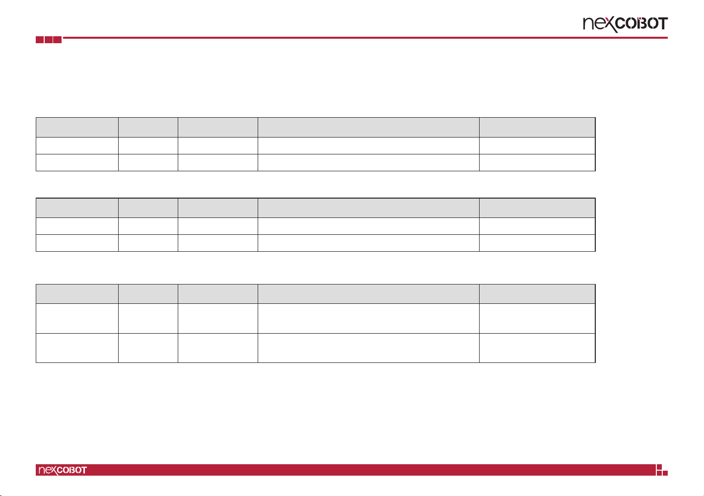
1.4 Model Designation
Digital Input Module
Model Name Channels Wiring Type Description Ordering Information
NEIO-B1101 32-ch PNP 24 VDC, filter 3 ms (IEC 61131-2 type 1/2/3) 10J80110100X0
NEIO-B1102 32-ch PNP/NPN 24 VDC, filter 1 ms 10J80110200X0
Digital Output Module
Model Name Channels Wiring Type Description Ordering Information
NEIO-B1201 32-ch NPN 24 VDC, output current 0.5 A 10J80120100X0
NEIO-B1202 32-ch PNP 24 VDC, output current 0.5 A 10J80120200X0
Mixed Digital Input/Output Module
Model Name Channels Wiring Type Description Ordering Information
NEIO-B1811 32-ch DI: PNP
DO: NPN
16-ch DI, 24 VDC, filter 3 ms (IEC 61131-2 type 1/2/3)
16-ch DO, 24 VDC, output current 0.5 A 10J80181100X0
NEIO-B1812 32-ch DI: PNP/NPN
DO: PNP
16-ch DI, 24 VDC, filter 1 ms
16-ch DO, 24 VDC, output current 0.5 A 10J80181200X0

Copyright © 2019 NexCOBOT Co., Ltd. All Rights Reserved. 5NEIO Series User Manual
Chapter 1: Product Introduction
Communication Module
Model Name Channels Description Ordering Information
NEIO-B1603 4-ch 24 VDC, 1 x RS-232/422/485, 3 x RS-422/485 10J80160300X0
Mixed Analog Input/Output Module
Model Name Channels Wiring Type Description Ordering Information
NEIO-B1841 8-ch AI, 2-ch AO
8-ch DI, 8-ch DO
AI: single-ended
DI: PNP/NPN
DO: PNP
8-ch AI, 16-bit, voltage, current (single-ended)
2-ch AI, 16-bit, voltage, current
8-ch DI, 24 VDC, filter 1 ms
8-ch DO, 24 VDC, output current 0.5 A
10J80184100X0
Model Name Channels Wiring Type Description Ordering Information
NEIO-B1842 4-ch AI, 2-ch AO
8-ch DI, 8-ch DO
AI: differential
DI: PNP/NPN
DO: PNP
4-ch AI, 16-bit, voltage, current (differential)
2-ch AI, 16-bit, voltage, current
8-ch DI, 24 VDC, filter 1 ms
8-ch DO, 24 VDC, output current 0.5 A
10J80184200X0

Copyright © 2019 NexCOBOT Co., Ltd. All Rights Reserved. 6NEIO Series User Manual
Chapter 1: Product Introduction
1.5 General Specifications
General Specifications
Dimensions (WxHxD) 155 x 95 x 57.4 mm
Weight 324 g ± 20%
Mounting DIN-Rail (35 mm) / wall mount
Operating Temperature 0 ~ +55 °C
Storage Temperature -40 ~ +85 °C
Relative Humidity 5~95 %, no condensation
Ingress Protection Ratings IP 20
Vibration Resistance IEC 60068-2-6 (2 G, 10~500 Hz, Sine, Operating)
IEC 60068-2-64 (2 Grms, 10~500 Hz, Random, Operating)
Shock Resistance IEC 60068-2-27 (25 G @ Din-rail, Half Sine, 11 ms, Operating)
Drop Resistance IEC 60068-2-32 (Gross weight: 324 g, falling height 97 cm)
EMC Immunity/Emission Conforms to EN 61000-6-2 / EN 61000-6-4
Certifications CE/FCC Class A

Copyright © 2019 NexCOBOT Co., Ltd. All Rights Reserved. 7NEIO Series User Manual
Chapter 1: Product Introduction
1.6 Mechanical Dimensions
155
57.4
39.35
8
115
95
4
6
3
4
3
6
35.8
1.5
R2.25
Copyright © 2019 NexCOBOT Co., Ltd. All Rights Reserved. 8NEIO Series User Manual
Chapter 1: Product Introduction
1.7 Hardware Installation Guidelines
This section includes information about how to wire and mount NEIO
modules.
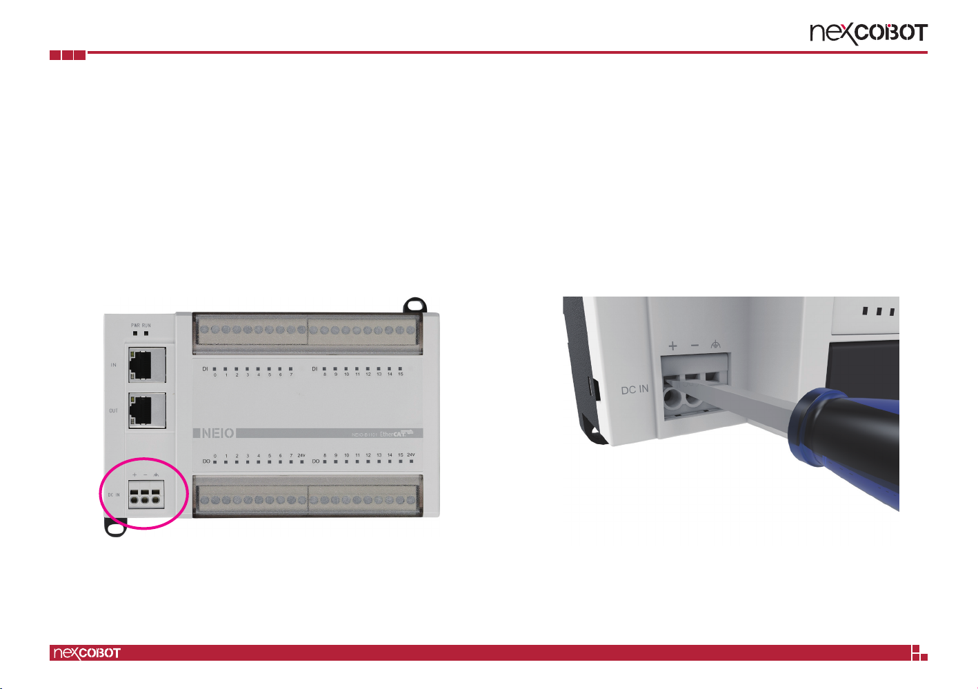
1.7.1 Wiring Instructions
▪Wiring the 24 VDC Power
1. The 3-pin connector on the bottom left side of the module is the
connector for 24 VDC input.
2. Insert a flat-tipped screw driver vertically into the square hole to open
the spring inside the terminal block.
Table of contents
Other NEXCOBOT Industrial Equipment manuals


Popular Industrial Equipment manuals by other brands


Eaton
Eaton COOPER POWER SERIES Assembly and installation instructions

Sentek
Sentek Sentek Hardware Integration Manual

ASTEC
ASTEC JCI Kodiak 300 Operation and Service Manual and Parts Book

Metal Work
Metal Work ONE Use and maintenance

Altechna
Altechna PowerXP user manual

Coremorrow
Coremorrow H60.XYZTR5S user manual