5
7.1 INTRODUCTION
Ingersoll Rand multiple module dryers remove moisture from
compressed air by cooling the air to a low temperature ( adjustable
between 32 and 50°F). This causes water vapor to condense into water
droplets which can then be easily removed from the air. The multiple
module design consists of two (2) or more Air / Refrigeration Modules.
All modules are connected by common Inlet and Outlet Headers. The
major systems of the dryer are: Air System, Moisture Removal System,
Refrigeration System and the Controls System The following sections
describe each of the systems in greater detail.
7.2 AIR SYSTEM
The Air System for each module consists of the dryer components which
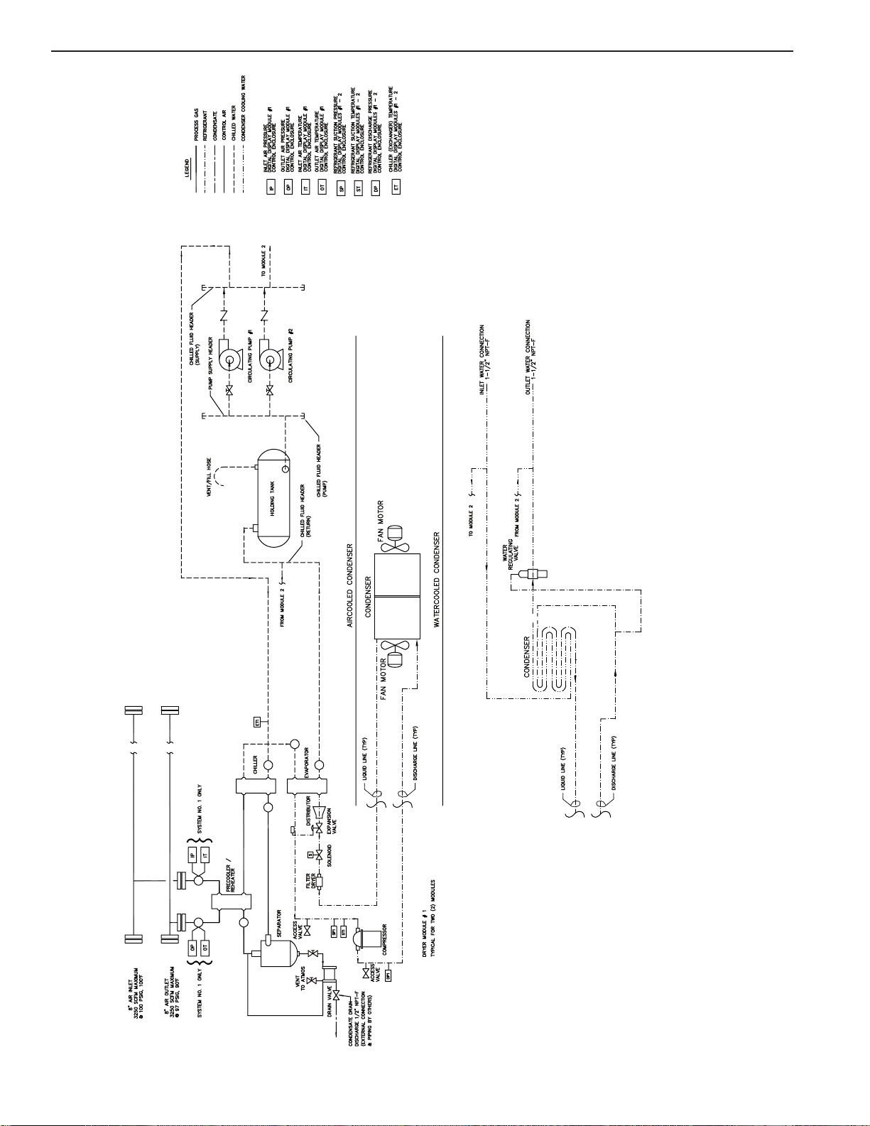
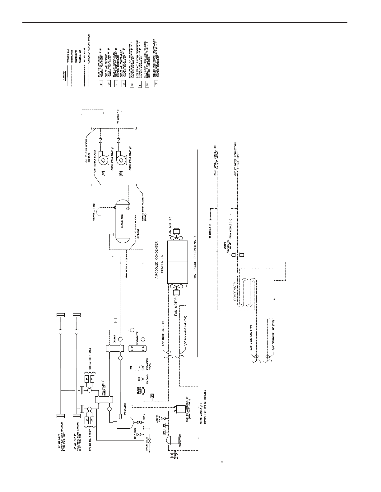
are in contact with the compressed air. Referring to the Flow Diagram
and following the bold “AIR FLOW,” hot saturated air from the air
compressor enters the inlet header and then the precooler/reheater
where the air temperature is reduced prior to entering the chiller by the
cool air exiting the air/moisture separator. The air then goes into the
chiller section where it is further cooled to the desired dew point by a
thermal mass fluid. The temperature of the thermal mass fluid is
maintained by the refrigeration circuit and controls. The air continues to
the separator where moisture is removed, thereby, allowing the cool, dry
air to return to the precooler/reheater to be heated by the incoming moist
hot air. The air exiting the “reheater” portion of the dryer should be
approximately 15°- 20°F lower than the inlet air temperature based on
standard conditions at full rated flow. Air from each module is collected
in the outlet header and exits the dryer.
7.3 MOISTURE REMOVAL SYSTEM
Ingersoll Rand condensate drains discharge condensed moisture and
lubricants (condensate) from compressed air equipment. The
condensate drain operates as a zero-air-loss drain, returning air that is
displaced in the drain bowl back into the compressed air system.
Consistent discharging of condensate from compressed air equipment
is essential for proper equipment operation and performance.
The drain valve is designed for trouble-free and maintenance free
draining of unwanted accumulations of condensation and other foreign
matter from any collection point in a compressed air system without the
need for electricity.
7.4 REFRIGERATION SYSTEM
The Refrigeration System consists of all the components in each module
that handles the R-404A refrigerant. This is a hermetically sealed
closed-loop system. Referring to Figure 1 and following the phantom
“REFRIGERANT” line, refrigerant for each module is shown leaving its
respective evaporator section where, in the process of removing heat, it
is changed from a low pressure liquid into a low pressure gas. This gas
enters the suction side of the compressor where it is compressed into a
high pressure gas. The high pressure gas is cooled in the air cooled or
water cooled condenser section until it becomes a high pressure liquid.
It then goes to a liquid receiver and through a permanent filter dryer that
ensures the refrigeration system is free of contaminants.
7.0 PRINCIPLES OF OPERATION
A thermostatic expansion valve meters the refrigerant for introduction
into the evaporator. The refrigerant pressure is reduced upon entering
the evaporator where as it evaporates, heat is removed from the thermal
mass fluid.
Heavy-duty hermetic compressors are standard on multiple module
dryers. These compressors are equipped with an oil sight glass and
internal overload controls.
7.5 THERMAL MASS CIRCULATING SYSTEM
The heat is removed from the fluid in the evaporator by the refrigeration
system. The thermal mass holding tank is sized to minimize refrigeration
cycles during reduced air load periods. The thermal mass fluid is pulled
from the bottom of the holding tank and pumped through the chiller,
removing heat from the air and then returned to the evaporator. While
the individual refrigeration systems cycle on and off based on loading
conditions, the circulating pump runs continuously to maintain flow
through the chiller at all times.
7.6 CONTROLS
Ingersoll Rand Refrigerated Compressed Air Dryers are equipped with
the Microprocessor Control on each module. This advanced
microprocessor-based controller has been engineered by Ingersoll
Rand exclusively for use with Ingersoll Rand Compressed Air Dryers.
The Microprocessor Control cycles the refrigeration system based on
the dryer's Chiller Temperature. A temperature sensor samples the
thermal mass temperature as it enters the chiller exchanger. The
Chiller Temperature Set point is a user adjustable set point that is used
to set the Refrigeration Compressor Off temperature. Once the Chiller
Temperature has fallen below the Chiller Temperature Set point, the
refrigeration compressor will de-energize. The Operating Temperature
Differential is factory set at 3°F above the Chiller Temperature Set point.
Therefore, if a user adjusts the Chiller Temperature at 36°F, the
Refrigeration Compressor On temperature will be 39°F.
The Microprocessor Control features three levels of access. The default
level CUSTOMER MODE permits adjustment of dryer parameters to
address seasonal variations for drain timing and pressure dew point
temperature. A protected TECHNICIAN MODE permits access to and
manipulation of additional parameters. A password protected
FACTORY MODE is also included for use with Ingersoll Rand Service
Personnel for troubleshooting the dryer.
Nirvana Cycling Refrigerated Dryer Models 3250-8000
ingersollrandproducts.com