EN
TL-2922-MIM_ed1 3
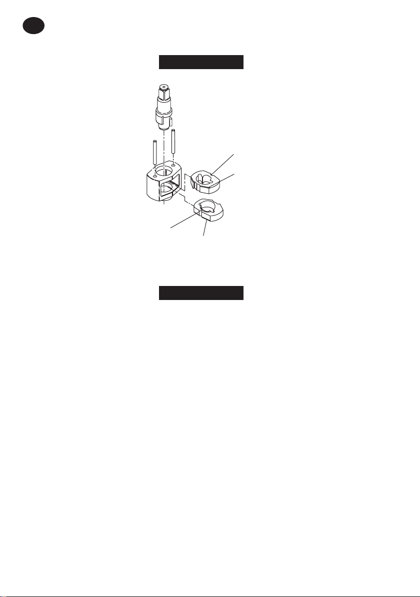
Disassembly of the Impact Mechanism
1. Set mechanism, driver end up, on a workbench.
NOTICE
●Note the twin hammers within the Hammer Frame. These are identical, but must be placed in the Hammer Frame in a particular
relationship. Using a felt-tipped pen, mark the top Hammer “T↑”and the bottom Hammer “B↑” with the arrows pointing upward.
Mark both Hammers on the same end.
2. With the mechanism sitting upright on a workbench, slowly rotate Anvil in a clockwise direction until it comes up solid.
NOTICE
●If you continue to rotate the Anvil, it will cam the Hammers out of engagement. Do not do this; merely rotate the Anvil until it comes
up solid.
3. Hold Hammer Frame rmly and, without disturbing Hammers, gently lift Anvil, simultaneously rotating it clockwise about 1/8 of a turn, from
the Hammer Frame.
4. With Anvil removed, lift out the two Hammer Pins.
NOTICE
●The twin hammers are now free to slide from the Hammer Frame. Be careful not to drop them.
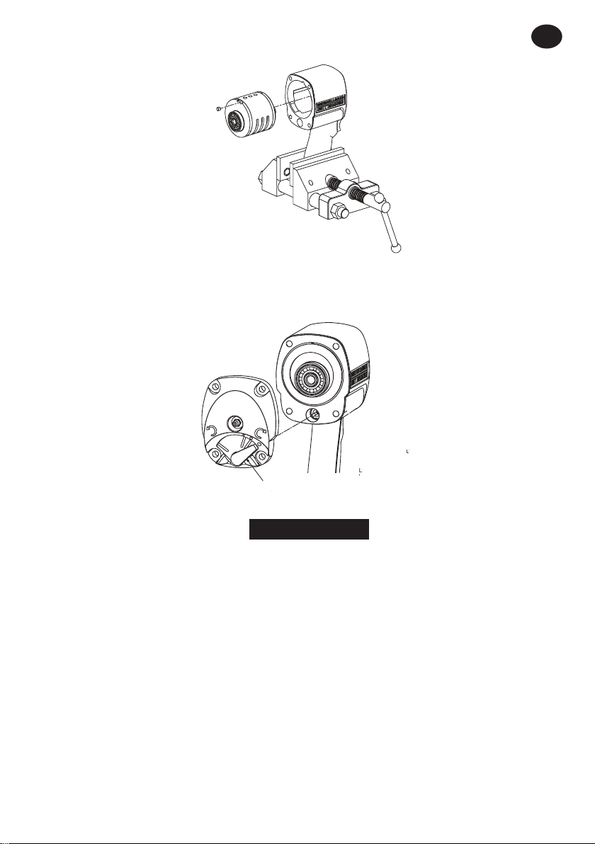
Disassembly of the Reverse Valve
1. Remove the four Backcap Bolts (14).
2. Lift the Backcap o of the rear of the Housing.
3. Discard the Backcap Gasket (15) and replace it with a new one when assembling the tool.
4. Use a hooked tool to remove the Reverse Valve (32) from the reverse Valve bushing. Set the Reverse Valve aside on a clean bench.
5. Remove and discard the Reverse Valve O-ring (31). Replace it with a new one when assembling Reverse Valve.
6. Use a at, thin blade Screwdriver to remove the Reverse Lever Retaining Ring (19) and Reverse Lever Spring (20) from the Reverse Lever (18).
7. Remove the Reverse Lever from the Backcap.
Disassembly of the Motor
1. Remove the four Backcap Bolts.
2. Remove the Backcap, Motor Clamp Washer (21) and Backcap Gasket from the Housing and set them aside on a clean bench. Discard the
Backcap Gasket and replace it with a new one when assembling the tool.
3. Lift the Housing from the Hammer Case. Place one hand over the rear of the Housing and turn the Housing over so that the assembled
motor can slide and be guide out of the Housing.
4. Place the assembled motor on a clean bench with the rotor spline facing upward.
5. Remove the Front End Plate (29) and Cylinder (27).
6. Remove the Rotor (25) from Rear End Plate (23).
7. Remove the Vanes from the Rotor.
8. Inspect all motor parts including the Front Rotor Bearing (30) and Rear Rotor Bearing (22) and replace all worn or damaged parts.
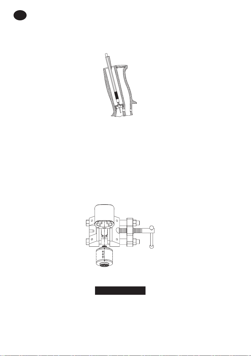
Disassembly of the Throttle Mechanism
1. Unscrew and remove the Air Inlet Bushing (8).
2. Remove the Screen (7), Throttle Valve Spring (6) and Throttle Valve (5).
3. If the Throttle Valve Seat (2) requires replacement, insert a hooked tool through the center of the Valve Seat. Catching the backside of the
Seat with the hook, pull the Seat from the Housing.
4. Withdraw the Trigger Assembly (3) from Housing.
5. Remove the Retaining Ring (11), Exhaust Deector (12) and Muer Element (10) from the Housing.
Assembly
General Instructions
1. Always press on the inner ring of a ball-type bearing when installing the bearing on a shaft.
2. Always press on the outer ring of a ball-type bearing when pressing the bearing into a bearing recess.
3. Whenever grasping a tool or part in a vise, always use Leather-covered or Copper-covered vise jaws. Take extra care with threaded parts or
housings.
4. Always clean every part and wipe every part with a thin lm of oil before installation.
5. Apply a lm of O-ring lubricant to all O-rings before nal assembly.
6. Check every bearing for roughness. Sealed or shielded bearings should never be cleaned. Work grease thoroughly into every open
bearing before installation.