Ingrasys iPoMan 8000 User manual

iPoMan 8000
User Manual


iiiiPoMan 8000
Preface
About this manual
Congratulations on purchasing the iPoMan 8000. This user manual provides
detailed descriptions of the hardware components and how to use it. Read
this manual carefully and follow the instructions while using the
iPoMan 8000.
Copyright information
No part of this manual, including the products and software described in it,
may be reproduced, transmitted, transcribed, stored in a retrieval system, or
translated into any language in any form or by any means, except documen-
tation kept by the purchaser for backup purposes, without the express writ-
ten permission of the manufacturer.
Products and corporate names appearing in this manual may or may not be
registered trademarks or copyrights of their respective companies, and are
used only for identification or explanation and to the owners’ benefit, with-
out intent to infringe. All trademarks are the property of their respective
owners.
Copyright © 2005. All rights reserved.
Warranty policy
TBA

iv iPoMan 8000
Safety instructions
Follow these safety instructions to avoid injury to self and damage to the
iPoMan 8000.
• To reduce the risk of fire or electric shock, install the unit in a tempera-
ture-controlled indoor area free of conductive contaminants. Do not
place the unit near liquids or in an excessively humid environment.
• Do not allow liquids or foreign objects to enter the unit.
• The unit does not contain any user-serviceable parts. Do not open the
unit.
• Servicing, maintenance, and repair for this equipment must be per-
formed by qualified service personnel. Remove rings, watches and
other jewelry before servicing the unit.
• Before maintenance, repair or shipment, the unit must be completely
switched off and unplugged and all connections must be removed.
• Before plugging in the power cord of the device, make sure that the
power source rating matches the power rating of the iPoMan 8000.
• Use a standard power cord when you connect any device to the outlets
of iPoMan 8000.
• This unit has been provided with a real time clock circuit. There is a
danger of explosion if the battery is incorrectly replaced. Replace only
with a 3V Lithium cell (CR2032) or equivalent type. Discard used bat-
teries according to the manufacturer’s instructions.

viPoMan 8000
Table of Contents
Introducing the iPoMan 8000
Features ................................................................................. 2
Package contents ................................................................... 3
Hardware components........................................................... 4
Front panel ..................................................................... 4
Status indicators ...................................................... 6
Using the control buttons ........................................ 7
Rear panel....................................................................... 9
Getting started
Attaching the feet ................................................................ 10
Attaching the ears................................................................ 10
Making connections ............................................................ 11
Connecting input power ............................................... 12
Connecting output devices ........................................... 13
Connecting digital outputs ........................................... 13
Connecting EMD ......................................................... 14
Connecting the console ................................................ 15
Connecting to a WAN.................................................. 15
Using the console menu
Using HyperTerminal.......................................................... 16
Navigating through the console menu................................. 18
Setting the IP address .......................................................... 20

vi iPoMan 8000
Using the web interface
Overview ............................................................................. 21
Modifying the basic settings ............................................... 22
Setting the date and time .............................................. 22
Adding users................................................................. 23
Changing event alert settings ....................................... 23
Modifying application settings............................................ 24
Setting control options ................................................. 24
Setting up a schedule.................................................... 25
Status ............................................................................ 25
Configuration ............................................................... 25
Appendix
Specifications ...................................................................... 26
Error codes .......................................................................... 27
Regulatory information ....................................................... 28
FCC Statement ............................................................. 28
CE................................................................................. 29
UL ................................................................................ 29

1iPoMan 8000
Introducing the iPoMan 8000
Congratulations on purchasing the iPoMan 8000, an intelligent power man-
agement system. The iPoMan 8000 provides the useful ability of managing
power for any combination of network equipment connected to it. You can
control the power on/off for any device connected to the iPoMan 8000,
manually or remotely, using a console or Ethernet connection. The
iPoMan 8000 comes with eight power outlets, each of which, can be moni-
tored and controlled through the console or web interfaces. You can also use
the front panel to operate the power outlets.
The iPoMan 8000 is also equipped with a console port for connecting an
EMD (Environmental Monitored Device) for sensing temperature and
humidity along with two alarms that can be activated when either of the sen-
sors show unusual values. The iPoMan 8000 is provided with two digital
outputs which you can use for connecting status indicators or digital
switches.
The device is designed to remember the configuration of each outlet and
inlet and is also able to measure the input and output current consumption.

Introducing the iPoMan 8000
2iPoMan8000
Features
• Eight power outlets that can be turned on or off in multiple ways, with
easy monitoring of current consumption
• Versatile sensors supported through EMD (Environmental Monitoring
Device) inputs
• Active extended devices via digital outputs
• Monitor and manage connected devices and sensors remotely
• Control the iPoMan 8000 manually, or remotely through console or
network
• Intelligent turn on/off devices based on event occurrence or planned
schedule
• Comprehensive power management and flexible configuration through
web browser, NMS, Telnet, SNMP, or HyperTerminal (console)
• Configurable user security control
• User-friendly interface to display input and output status
• Detailed data-logging for statistical analysis and diagnostics
• Upgrade utility for easy firmware upgrade
• Event notification through SNMP trap or Email alerts
• Daily history report through Email
• Supports SSL V3 and SSH V1 protocol
• Administrator and multiple users with password protection for dou-
ble-layer security
• Address-specific IP security masks to prevent unauthorized access
• Available in 110V and 220V models
Introducing the iPoMan 8000
3iPoMan 8000
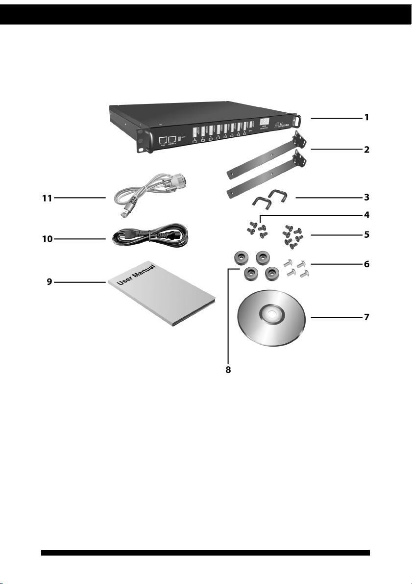
Package contents
Make sure that your package has the following items. If any of items is
missing or damaged, contact your nearest service center or vendor.
1. iPoMan 8000
2. Ears (x2)
3. U-type handle (x2)
4. U-type handle screws (x4)
5. Ear screws (x6)
6. Feet screws (x4)
7. Software CD
8. Feet (x4)
9. User manual
10. Power cord
11. Serial cable
Introducing the iPoMan 8000
4iPoMan8000
Hardware components
Take a moment to familiarize yourself with the iPoMan 8000 front and rear
panels. The following sections provide descriptions about the front and rear
panel components and how to use them.
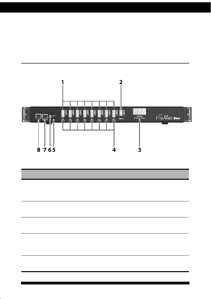
Front panel
Component Description
1. Output power status
indicator (A ~ H)
Displays output current, power status, and
remote control status for each power outlet A
through H.
2. Input power consump-
tion indicator
Displays percentage of input power
consumed.
3. Status indicator Displays input current, voltage, frequency,
and error code.
4. Remote control button Enables you to manually control power and
enable remote control configuration for each
power outlet A through H.
5. Reset button Enables you to reset the iPoMan 8000 in case
the system locks up.

Introducing the iPoMan 8000
5iPoMan 8000
6. Operation mode DIP
switch
Sets the mode of operation for the
iPoMan 8000.
S1 off, S2 off: Normal operation (default
mode)
7. Serial (CONSOLE)
port
Enables you to configure the iPoMan 8000
using the serial port. You can also connect an
optional EMD to this port.
8. Ethernet (LAN) port Enables you to configure the iPoMan 8000
through a LAN or WAN.
Component Description

Introducing the iPoMan 8000
6iPoMan8000
Status indicators
The front panel of the iPoMan 8000 has several LED indicators that provide
information about the input and output power status. The following table
describes these status indicators.
Status indicator Description
Output power status indicator
(A ~ H)
Displays status of each power outlet (A ~ H)
as follows:
1. Current level indicator: Displays the
amount of current being drawn by the con-
nected output device through the power
outlet.
2. Outlet power indicator: Displays the out-
let power status.
–Grey: power off
–Green: power on
3. Remote control indicator: Displays the
remote control status of each outlet.
–Grey: remote control is enabled.
–Red: remote control is disabled.
4. Control button: Allows manual control of
each power outlet. Press repeatedly to
switch between remote control and power
on/off mode. See “Using the control but-
tons” on page 7.
Input power consumption
indicator
Displays input power consumed by the output
devices connected to the iPoMan 8000 outlets.
The power consumption is displayed as a per-
centage value.
80%
50%
30%
20%
10%
5%
A
1
2
3
4
80%
50%
30%
20%
10%
5%
INPUT

Introducing the iPoMan 8000
7iPoMan 8000
Using the control buttons
You can turn on power manually for each of the eight output devices with
the control buttons provided under each status indicator A through H. Each
button allows you to set the remote control function as well as turn power
on/off for each outlet manually.
The control button has two modes of operation. Press the button repeatedly
to switch between Remote Control mode and Power On/Off mode. When
you press the control button, the iPoMan 8000 switches modes as follows:
After switching modes, you need to press the control button again within
5 seconds to change the mode status.
Remote control mode
1. Press the control button once. The remote control indicator starts
flashing red.
2. Now press control button again within 5 seconds and hold for more
than 5 seconds. The remote control indicator starts flashing red at a
faster speed and then inverts its original state.
For instance, if remote control indicator is enabled (grey) before you press
the control button, it turns on (red) after step 2, indicating that remote con-
trol is disabled.
Input power status indicator Displays input voltage (Volts), input current
(Ampere), and frequency (Hz), sequentially on
the 7-segment switching display. This indica-
tor also shows system errors in the form of an
error code such E01, E02, E03, and so on.
Refer to “Error codes” on page 27 under the
appendix for a list of all error codes.
Status indicator Description
STATUS
Volt./Amp./Hz./Code
Original state Remote Control
mode
Power On/Off
mode

Introducing the iPoMan 8000
8iPoMan8000
Power on/off mode
1. Press the control button twice. The outlet power indicator starts flash-
ing green.
2. Now press control button again within 5 seconds and hold for more
than 5 seconds. The outlet power indicator starts flashing green at a
faster speed and then inverts its original state.
For instance, if outlet power indicator is off (grey) before you press the con-
trol button, it turns on (green) after step 2, indicating that outlet power is
turned on.

Introducing the iPoMan 8000
9iPoMan 8000
Rear panel
Component Description
1. Input power Connect to a power outlet.
2. Breaker Prevents excessive current flow to protect the
system.
3. Power outlet (A ~ H) Connect a device to each power outlet to sup-
ply power to it.
4. Dry contact port Connect dry contact UPS that can be remotely
managed through network card. This is cur-
rently not supported by the iPoMan 8000.
5. Digital output Connect up to digital outputs that are nor-
mally open or normally closed.
220V AC model
110V AC model
Rear panel components
10 iPoMan 8000
Getting started
This section provides information about setting up the iPoMan 8000, con-
necting power, and connecting devices to it before you start using it for
power management. Read this section carefully to learn how to connect var-
ious devices to it.
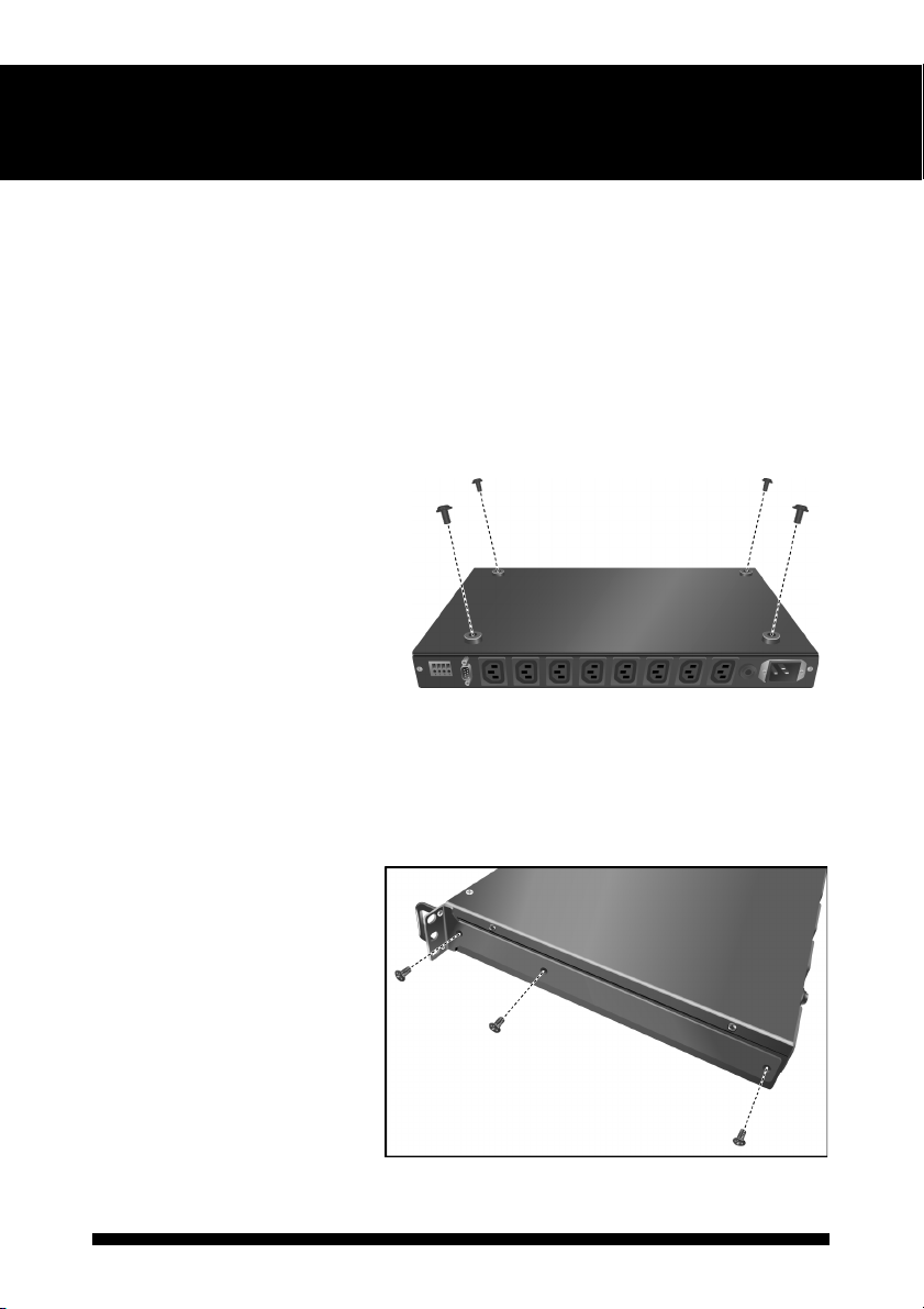
Attaching the feet
The iPoMan 8000 comes with
four feet or spacers that are
attached to the bottom. Use
the four screws provided with
the feet to attach the feet to
the bottom of the
iPoMan 8000 as shown:
Note: You do not need to attach
the feet if you are going to install
the iPoMan 8000 in a rack.
Attaching the ears
The iPoMan 8000 is
designed to be placed in a
rack arrangement and comes
with two ears that help you
to move the device easily.
Attach each ear with the
three screws provided in
your package as shown:

Getting started
11iPoMan 8000
Making connections
The iPoMan 8000 is a versatile product that can be connected to several dif-
ferent types of input and output devices. This makes it a useful tool for con-
necting devices to it and controlling their power on/off status through its
user interface.
The iPoMan 8000 can be attached to eight output devices whose power sta-
tus can be controlled remotely and manually. It also supports an EMD
(Environmental Monitored Device) or sensors for detecting environmental
conditions as well as digital outputs or devices with normally open or nor-
mally closed conditions. Moreover, the iPoMan 8000 supports a serial (con-
sole) and Ethernet (LAN/WAN) connection that lets you control the
iPoMan 8000 outputs remotely.
The following procedure describes the basic steps needed to set up the
iPoMan 8000:
1. To set up the hardware, connect power to the power inlet and output
devices to the power outlets. Connect digital outputs to the digital I/O
ports, and an EMD to the console port.
Note: The EMD is optional.

Getting started
12 iPoMan 8000
2. To configure the iPoMan 8000, you can use the console or WAN
port. Connect the iPoMan 8000 to a console and a WAN to enable its
configuration through the console or browser menu.
3. After connecting to a console, use a console application such as Tel-
net or HyperTerminal to access the console menu. Select the System
Group submenu under the iPoMan Configuration to set up the IP
address and the system date/time. This IP address will be used while
accessing the web interface to configure the iPoMan 8000 parame-
ters.
4. After connecting to WAN, open a browser from a PC in the network
and use the iPoMan 8000 IP address specified through the console
menu to open the web interface for system configuration.
The following sections provide instructions about how to make various con-
nections.
Connecting input power
The iPoMan 8000 has an IEC C20 power inlet for supplying and managing
power for the output devices. Connect the power cord to the power inlet and
plug the other end into a power outlet as shown:

Getting started
13iPoMan 8000
Connecting output devices
The iPoMan 8000 has eight power outlets for connecting devices such as
workstations, servers, and printers. Their power on/off status can be con-
trolled manually as well as remotely through the LAN and Console ports.
Connect the power connectors of the devices to each of the power outlets A
through H with the power cords supplied with the devices as shown:
Connecting digital outputs
The iPoMan 8000 provides two digital outputs to which you can connect
switches, indicators, or other output devices that are normally open or nor-
mally closed. You can control the digital outputs remotely through the con-
sole or over the LAN.
Getting started
14 iPoMan 8000
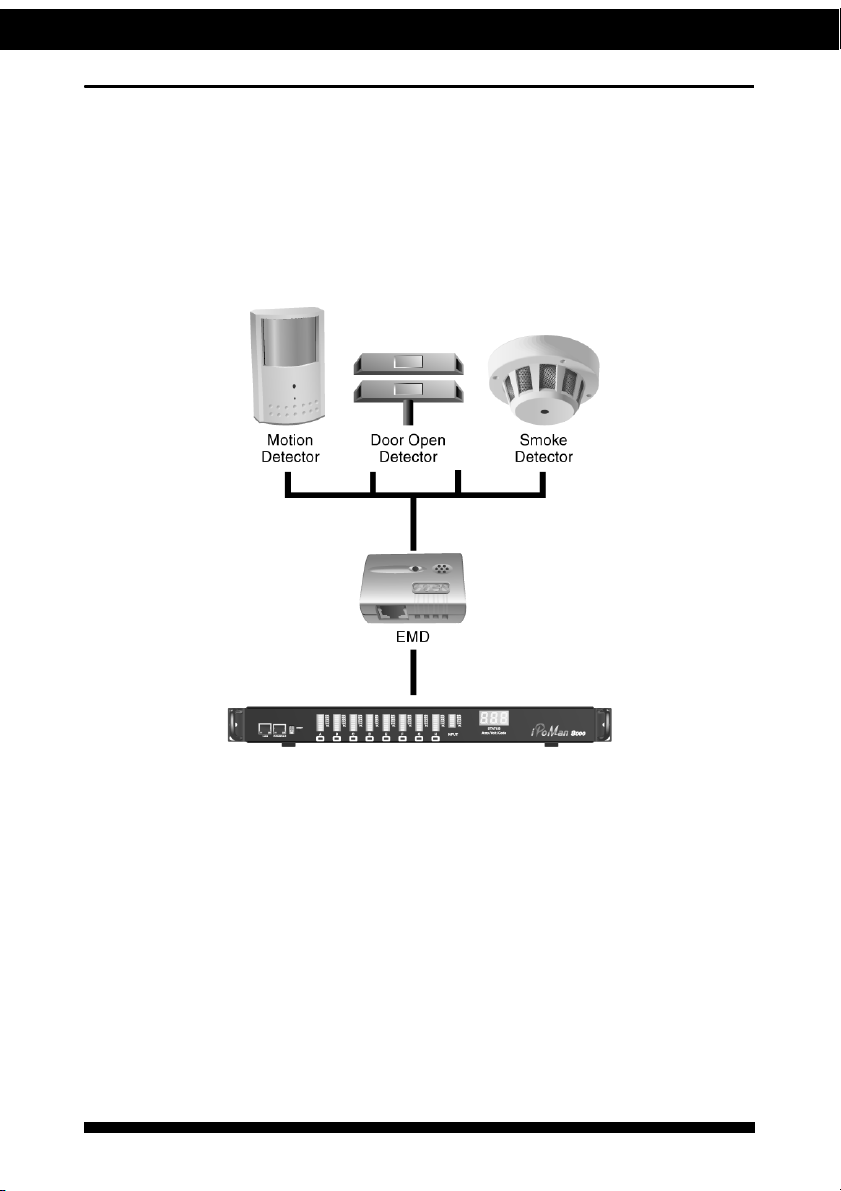
Connecting EMD
An environmental monitored device that is connected to sensors for detect-
ing temperature, humidity, water level, and so on can be connected to the
iPoMan 8000 with the console port. The EMD can also be connected to
alarms or indicators and controlled through the iPoMan 8000. Connect the
EMD to the console port as shown:
Table of contents
Other Ingrasys Power Distribution Unit manuals


