Ingrasys iPoMan II-1200 User manual

Power Distribution Unit
(iPoMan II-1200)
V
Ve
er
rs
si
io
on
n
1
1.
.0
0

iPoMan II-1200
~2~
Preface
About this Manual
Congratulations on purchasing the iPoMan II-1200. This user
manual provides detailed descriptions of the hardware
components and how to use the iPoMan II-1200. Read this
manual carefully and follow the instructions while using the
iPoMan II-1200.
Copyright Information
No part of this manual, including the products and software
described in it, may be reproduced, transmitted, transcribed,
stored in a retrieval system, or translated into any language in
any form or by any means, except documentation kept by the
purchasers for backup purposes, without the express written
permission of the manufacturer.
Products and corporate names appearing in this manual may or
may not be registered trademarks or copyrights of their
respective companies, and are used only for identification or
explanation and to the owners’ benefit, without intent to
infringe. All trademarks are the property of their respective
owners.
Copyright © 2007. All rights reserved.

iPoMan II-1200
~3~
Safety Instructions
Follow these safety instructions to avoid injury to self and
damage to the iPoMan II-1200.
•To reduce the risk of fire or electric shock, install the
unit in a temperature-controlled indoor area free of
conductive contaminants. Do not place the unit near
liquids or in an excessively humid environment.
•Do not allow liquids or foreign objects to enter the unit.
•The unit does not contain any user-serviceable parts. Do
not open the unit.
•Servicing, maintenance, and repair for this equipment
must be performed by qualified service personnel.
Remove rings, watches and other jewelry before
servicing the unit.
•Before maintenance, repair or shipment, the unit must be
completely switched off and unplugged and all
connections must be removed.
•Before plugging in the power cord of the device, make
sure that the power source rating matches the power
rating of the iPoMan II-1200.
•Use a standard power cord when connecting any device
to the outlets of iPoMan II-1200.
•The digital output only can connect switches, indicators,
or other output devices that are normally open or
normally closed.

iPoMan II-1200
~4~
Safety Notices
Caution:
This unit has been provided with a real time
clock circuit. There is a danger of explosion
if the battery is incorrectly replaced.
Replace only with a 3V Lithium cell
(CR2032) or equivalent type. Discard used
b
atteries according to the manufacturer’s
instructions.
Caution:
Rack-Mounted Equipment – The unit is
intended to be rack-mounted, the
Installation Instructions shall contain
wording to address the following concerns
when the unit is mounted in a rack system.
A.
“The equipment is to be installed
in an environment with maximum
ambient temperature must not
exceed 50°C.”
B. “The openings on the enclosure
are for air convection hence
protected the equipment from
overheating. DO NOT COVER
THE OPENINGS.”
C. “Lay this equipment on a reliable
surface when install. A drop or
fall could cause injury.”
D. “The equipment shall be installed
according to specification as
nameplate. Make sure the voltage
of the power source when connect
the equipment to the power outlet.
The current of load and output

iPoMan II-1200
~5~
power of loads shall be not over
the specification.”
E. “This equipment must be
connected to the reliable earth
before using.”

iPoMan II-1200
~6~
Table of Content
Preface......................................................................... 2
About this Manual................................................................... 2
Copyright Information............................................................ 2
Safety Instructions .................................................................. 3
Safety Notices......................................................................... 4
Introduction the iPoMan II-1200.............................. 7
Features................................................................................... 8
Package Contents.................................................................... 9
Hardware Components.......................................................... 10
Getting Started ......................................................... 14
Attaching the Feet................................................................. 14
Attaching the Ears................................................................. 14
Rack Mounting...................................................................... 14
Making Connections............................................................. 15
Daisy Chaining...................................................................... 20
Using the Console Menu.......................................... 23
Using HyperTerminal ........................................................... 23
Navigating through the Console Menu................................. 25
Setting the IP Address........................................................... 27
Using the Web Interface.......................................... 28
Overview............................................................................... 28
Modifying the Basic Settings................................................ 29
Modifying Application Settings............................................ 31
Appendix................................................................... 35
Specifications........................................................................ 35
Error codes............................................................................ 37
Regulatory Information......................................................... 38

iPoMan II-1200
~7~
Introduction the iPoMan II-1200
Congratulations on purchasing the iPoMan II-1200, an
intelligent power management system. The iPoMan II-1200 is
designed to measure the input and individual outlet current
consumption and auto email history report to supervisor for
power bill charge. At the same time, the iPoMan II provides the
useful ability of managing power for any combination of
network equipment connected to it. User can control the power
on/off for any device connected to the iPoMan II-1200,
remotely, using a console or Ethernet connections. The iPoMan
II-1200 comes with twelve power outlets, each of which can be
monitored and controlled through the console or web interfaces.
The iPoMan II-1200 is also equipped with a console port for
connecting an EMD (Environmental Monitoring Device) for
sensing temperature and humidity along with two alarms that
can be activated when either of the sensors shows unusual
values. The iPoMan II-1200 is provided with two digital outputs
which users can use for connecting status indicators or digital
switches.

iPoMan II-1200
~8~
Features
•To calculate the power consumption on hourly basis, and
have an accumulation of daily
•Provide detail data-logging for statistical analysis and
diagnostic then auto email daily history report
•Daisy-chaining can cascade up 6 pieces iPoMan II
•Sequential power-up on the outlets / Allows users to
configure the sequence in which power is turned on or
off for each outlet
•Intelligently turn on/off devices based on event
occurrence or planned schedule
•Event notification by pop-up/Sending Trap or E-Mail for
events notification
•Twelve power outlets that can be turned on or off in
multiple ways, with easy monitoring of current
consumption
•Set over-current watchdog for each outlet (Threshold
settings for over-current warnings and alerts)
•Versatile sensors supported through EMD
(Environmental Monitoring Device) inputs
•Activate extended devices via digital outputs
•Comprehensive power management and flexible
configuration through web browser, NMS, Telnet,
SNMP, or HyperTerminal (console)
•Support Secure Socket Layer V3 and Secure Shell V1
protocols
•Administrator and multiple users with password
protection for double-layer security
•Address-specific IP security masks to prevent
unauthorized access
•User-friendly interface to display input and output status
•Upgrade utility for easy firmware upgrade
•Available in 120V and 230V models

iPoMan II-1200
~9~
Package Contents
Make sure the iPoMan II-1200 package has the following items.
If any of items is missing or damaged, contact your nearest
service center or vendor.
1. iPoMan II-1200
2. Ears (x2)
3. U-type handles (x2)
4. U-type handle screws (x4)
5. Ear screws (x6)
6. Feet screws (x4)
7. Software CD
8. Feet (x4)
9. Quick Install Guide
10. Power cord (x2) for 2-inlet model;
Power cord (x1) for 1-inlet model
11. Serial cable

iPoMan II-1200
~10~
Hardware Components
Take a moment to familiarize yourself with the iPoMan II-1200
front and rear panels. The following sections provide
descriptions about the front and rear panel components and how
to use them.
Front Panel of 2-inlet Model
Front Panel of 1-inlet Model
Component Description
1. Input power status
indicator 2-inlet Model: Display power status for
each input power G1 through G2
1-inlet Model: Display power status for the
input power G1
2. Output power status
indicator (A ~ L) Display power status for each power outlet
A through L
3. Status indicator Display input current, voltage, frequency,
12
3
4
5
67
8 9

iPoMan II-1200
~11~
error code and the number of Daisy-
chaining
4. Daisy-chaining Mode
DIP Switch (C-link
DIP)
Set the mode of Daisy-chaining for
iPoMan II-1200.
Auto mode: For the master iPoMan II-
1200, set all the DIP switches of the C-
link to ON by moving all the switches
downward; for all the other iPoMan II-
1200s (slave iPoMan IIs) in the Daisy
Chain, set all the DIP switches of the C-
link to OFF by moving all the switches
upward. After setting the DIP switches for
all the iPoMan II-1200s in the Daisy
Chain, the Daisy Chain ID can be assigned
for each iPoMan II-1200 automatically.
Manual mode: The Daisy Chain ID for all
iPoMan II-1200s is assigned by user
manually. Please refer to DIP Switch
Setting Table on page 21.
5. Reset button Enable you to reset the iPoMan II-1200 in
case the system locks up.
6. Operation mode DIP
switch Set the mode of operation for the iPoMan
II-1200.
Default mode (S1 off, S2 off): Set the DIP
switches S1 and S2 to OFF by moving the
switches upward for normal operations.
7. Serial (CONSOLE)
Port Enable you to configure the iPoMan II-
1200 using the serial port. User can also
connect an optional EMD to this port.
8. Digital output Connect up to digital outputs that are
normally open or normally closed.
9. Breaker Prevent excessive current flow to protect
the system.

iPoMan II-1200
~12~
Status indicators
The front panel of the iPoMan II-1200 has several LED
indicators that provide information about the input and output
power status. The following table describes these status
indicators.
Status indicator Description
Input and Output
power status indicator
Display status of each power input and
outlet (A ~ L) as follows:
Input/Output power indicator: Display the
input / Output power status.
- Gray: power off
- Green: power on
- Red: power fault
Input power status
indicator
Display input voltage (Volts), input current
(Amps), frequency (Hz), and the number of
Daisy-chaining, sequentially on the 7-
segment switching display. This indicator
also shows system errors in the form of an
error code such E01, E02, E03 and so on.
Refer to “Error codes” on page 37 under the
appendix for a list of all error codes.
Rear Panel of 2-inlet Model
4
1 2
3
A B C D E F G H I J K L

iPoMan II-1200
~13~
Rear Panel of 1-inlet Model
Rear Panel Components
Component Description
1. Input power(G1 ~
G2) Connect to a power outlet
2-inlet model:
* G1 supplies power to outlet A to F
* G2 supplies power to outlet G to L
1-inlet model:
* G1 supplies power to outlet A to L
2. Power Outlet(A ~ L) Connect a device to each power outlet to
supply power to it.
Note: Three outlets group into one unit and
the maximum load is 10 Amps for one unit or
one outlet.
3. Daisy-chaining (C-
link ) port Enable user to cascade next iPoMan II
through an USB cable.
4. Ethernet (LAN) port Enable user to configure the iPoMan II-
1200 through a LAN or WAN
A B C D E F G H I J K L
Getting Started
This section provides information about setting up the iPoMan
II-1200, connecting power, and connecting devices to it before
users start using it for power management. Read this section
carefully to learn how to connect various devices to the iPoMan
II-1200.
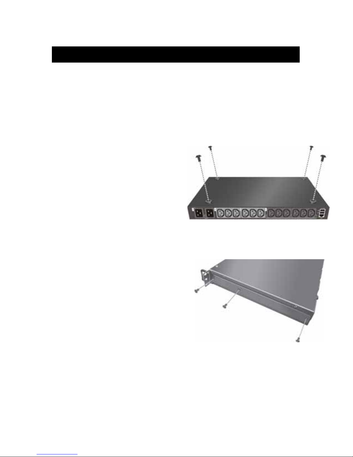
Attaching the Feet
The iPoMan II-1200 comes with
four feet or spacers that are
attached to the bottom. Use the
four screws provided with the
feet to attach the feet to the
bottom of the iPoMan II-1200 as
shown:
Note: Users do not need to attach
the feet if users are going to install the iPoMan II-1200 in a rack.
Attaching the Ears
The iPoMan II-1200 is designed to
be placed in a rack arrangement
and comes with two ears
(mounting brackets) that help users
to move the device easily. Attach
each ear with the three screws
provided in the package.
Rack Mounting
The iPoMan II-1200 can be installed in most standard 19” (1U)
racks. After attaching the ears to each side of the device,
position the device in the rack and align the holes in the ears
(mounting brackets) with the hole in the rack. Use the screws
supplied with your racks to tighten the ears (mounting brackets)

iPoMan II-1200
~15~
to the rack.
Making Connections
The iPoMan II-1200 is a versatile product that can be connected
to several different types of input and output devices. This
makes it a useful tool for connecting devices to it and
controlling their power on/off status through its user interface.
The iPoMan II-1200 can be attached to twelve output devices
whose power status can be controlled remotely. It also supports
an EMD (Environmental Monitoring Device) connecting with
sensors for detecting environmental conditions as well as digital
outputs for enabling devices with normally open or normally
close conditions. Moreover, the iPoMan II-1200 supports a
serial port (console) and Ethernet (LAN/WAN) connection that
lets users control the iPoMan II-1200 outputs remotely.

iPoMan II-1200
~16~
The following procedure describes the basic steps needed to set
up the iPoMan II-1200:
1. To set up the hardware, connect power to the power inlet and
output devices to the power outlets. Connect devices with
normally open or normally close conditions to the digital
output ports, and an EMD to the console port.
2. To configure the iPoMan II-1200, users can use the console
or LAN port. Connect the iPoMan II-1200 to a console and a
LAN to enable its configuration through the console or
browser menu.
3. After connecting to a console, use a console application such
as Telnet or HyperTerminal to access the console menu.
Select the System Group submenu under the iPoMan II-
1200 Configuration to set up the IP address and the system
date/time. This IP address will be used while accessing the
web interface to configure the iPoMan II-1200 parameters.
4. After connecting to LAN, open a browser from a PC in the
network and use the iPoMan II-1200’s IP address specified
through the console menu to open the web interface for
system configuration.
The following sections provide instructions about how to make
various connections.
Connecting Input Power
The 2-inlet model of the
iPoMan II-1200 has two
IEC C20 power inlets for
supplying and managing
power for the output
devices. The 1-inlet
model has just one inlet
for supplying power to all

iPoMan II-1200
~17~
outlets. For each inlet, connect the power cord to the power inlet
and plug the other end into a power outlet as shown:
Connecting Output Devices
The iPoMan II-1200 has twelve power outlets for connecting
devices such as workstations, servers, and printers. Their power
on/off status can be controlled remotely through the LAN and
Console ports. Connect the power connectors of the devices to
each of the power outlets A through L with the power cords
supplied with the devices as shown:
Connecting Digital Outputs
The iPoMan II-1200 provides two digital outputs to which users
can connect switches, indicators, or other output devices that are
normally open or normally close. Users can control the digital
outputs remotely through the console or over the LAN/WAN.

iPoMan II-1200
~18~
Connecting EMD
An Environmental Monitoring Device (EMD) that is connected
to sensors for detecting temperature, humidity, water leak, and
so on can be connected to the iPoMan II-1200 with the console
port. The EMD can also be connected to alarms or indicators
and controlled through the iPoMan II-1200. Connect the EMD
to the console port as shown:
After connecting to EMD, open a browser from a PC in the
network. The temperature and humidity status is automatically
displayed on the iPoMan II Status page.

iPoMan II-1200
~19~
Connecting the Console
Users can control the
output devices and manage
the power status through a
console or serial connection
with a PC. Use the serial
cable provided in the
iPoMan II-1200 package to
connect the COM port of
the PC and the CONSOLE
port of the iPoMan II-1200
as shown.
Refer to Using the Console Menu on page 23 to learn how to use
the console with a console application such as HyperTerminal or
Telnet.
Connecting to a LAN/WAN
The iPoMan II-1200 has an RJ-45 LAN connection that enables
users to monitor and manage
the power outlets and digital
outputs over the network.
The iPoMan II-1200 has a
graphic user interface that
allows users to control the
device through a web
browser. Connect the
iPoMan II-1200 to a free port
on the router using an
Ethernet cable as shown.
Users can then control the iPoMan II-1200 from PC, laptop,
mobile phone, or PDA which is connected to the router network.
Refer to page 28 for details about how to control the iPoMan II-
1200 and its output devices through the web.

Daisy Chaining
To manage more devices, up to 5 additional iPoMan II-1200s
can be daisy chained to the first unit. Follow instructions below
to set up a daisy chained installation.
1. For each iPoMan II-1200 that you add to the chain, use USB
cables to connect it to the parent iPoMan II-1200’s C-Link Port.
The upper C-Link port( ) of child iPoMan II is connected to
lower C-Link port( ) of its parent iPoMan II and the lower C-
Link port( ) of the lowest level iPoMan II is connected to the
highest level parent’s upper C-Link port( ) to form a
cyclic(ring) structure as illustrated in the following figure.
2.
The daisy chained installation can operate in Auto mode or Manual
mode. Use Daisy-chaining Mode DIP Switch (C-link DIP) to set the
operation mode.
Auto mode: For the master iPoMan II-1200, set all the DIP switches
of the C- link to ON by moving all the switches downward; for all the
other iPoMan II-1200s (slave iPoMan IIs) in the Daisy Chain, set all
Other manuals for iPoMan II-1200
1
Table of contents
Other Ingrasys Power Distribution Unit manuals


