Pts PTS90X3X Series User manual

1
PTS90X3X Series
PTS91X3X Series
PTS92X3X Series
120V/208V/240V AC Power Distribution Panel
60A - 125A Main Breaker
Suitable for Use as Service Equipment
Small Cell, Pico, Micro, CRAN or Macro
INSTALLATION GUIDE
Single SPD (L-G) per Leg or Dual SPD (L-N)per Leg, (N-PE)
PTS90X3X - 70A, 120V/208V/240V AC, 12 UL489 Breaker Positions
PTS91X3X - 100A, 120V/208V/240V AC, 16 UL489 Breaker Positions
PTS92X3x - 125A, 120V/208V/240V AC, 12, 16 or 20 UL489 Breaker Positions
All Rights Reserved, 2020
1-888-820-3508
www.pts5g.com
www.pactechsol.com

2
All Rights Reserved, 2020
1-888-820-3508
Table of Contents
1.0 Model Overview .............................................................................................................................3
Figure 1: Dimensional Drawings. ................................................................................................ 4
1.1 Specifications..............................................................................................................................5
1.2Breaker Load Out Examples.........................................................................................................6
1.3Application………………………………………………………………………………………..…….....7
2.0 Features..........................................................................................................................................7
2.1 Main Breaker...............................................................................................................................7
2.2 Distribution Breakers...................................................................................................................7
2.3 Optional Surge Protection Device……………………………………………………………..............7
2.4 Optional External Disconnect Switch ...........................................................................….....…...7
3.0 Inspecting and Unpacking ..............................................................................................................8
4.0 Mounting. .......................................................................................................................................8
4.1 Mounting Bracket..................................................................................................................................8
4.2 Mount enclosure vertically on surfaces.........................................................................................8
4.3 Removing Front Door / Access Cover.……………..……………………………………………….....8
4.4 Wiring Ground Connections…………………………………………………………………………..…9
4.5 Wiring Service and Load Connections………………………………………………………………..10
Figure 4: Standard Wiring Space Example................................................................................. 11
Figure 5: PTS9000 Series External Disconnect Switch Location......................…………………..12
5.0 Installation Review........................................................................................................................ 13
6.0 Document and Revision Control…………………………………………………………………..…….14
www.pts5g.com
Figure 3– Location of External Ground Connection………………………………………………....9
PTS9XX3X Series Small Cell
120/240V AC Power Distribution Load Centers
Installation Guide
www.pactechsol.com

3
1.0 Model Overview
The PTS9XX3X Series of Small Cell 120/240V AC Power Distribution Panels with
optional External Disconnect Switch,provides a custom factory fully assembled load
center for Small Cell, Pico, Micro, CRAN and Macro Deployments.
The PTS9XX3X Series products are SUSE Rated:
Suitable for Use as Service Equipment and conform to UL standards.
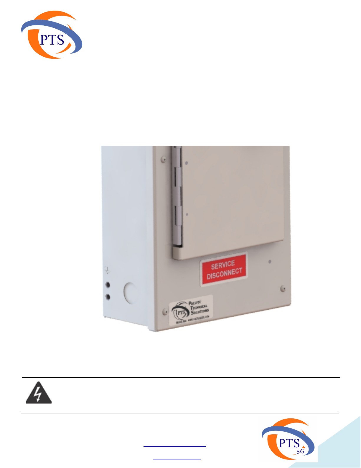
PTS9XX3X Series Small Cell AC Power Distribution Load Centers
PTS9XX3X Series Small Cell
120/240V AC Power Distribution Load Centers
Installation Guide
All Rights Reserved, 2020
1-888-820-3508
www.pts5g.com
www.pactechsol.com
4
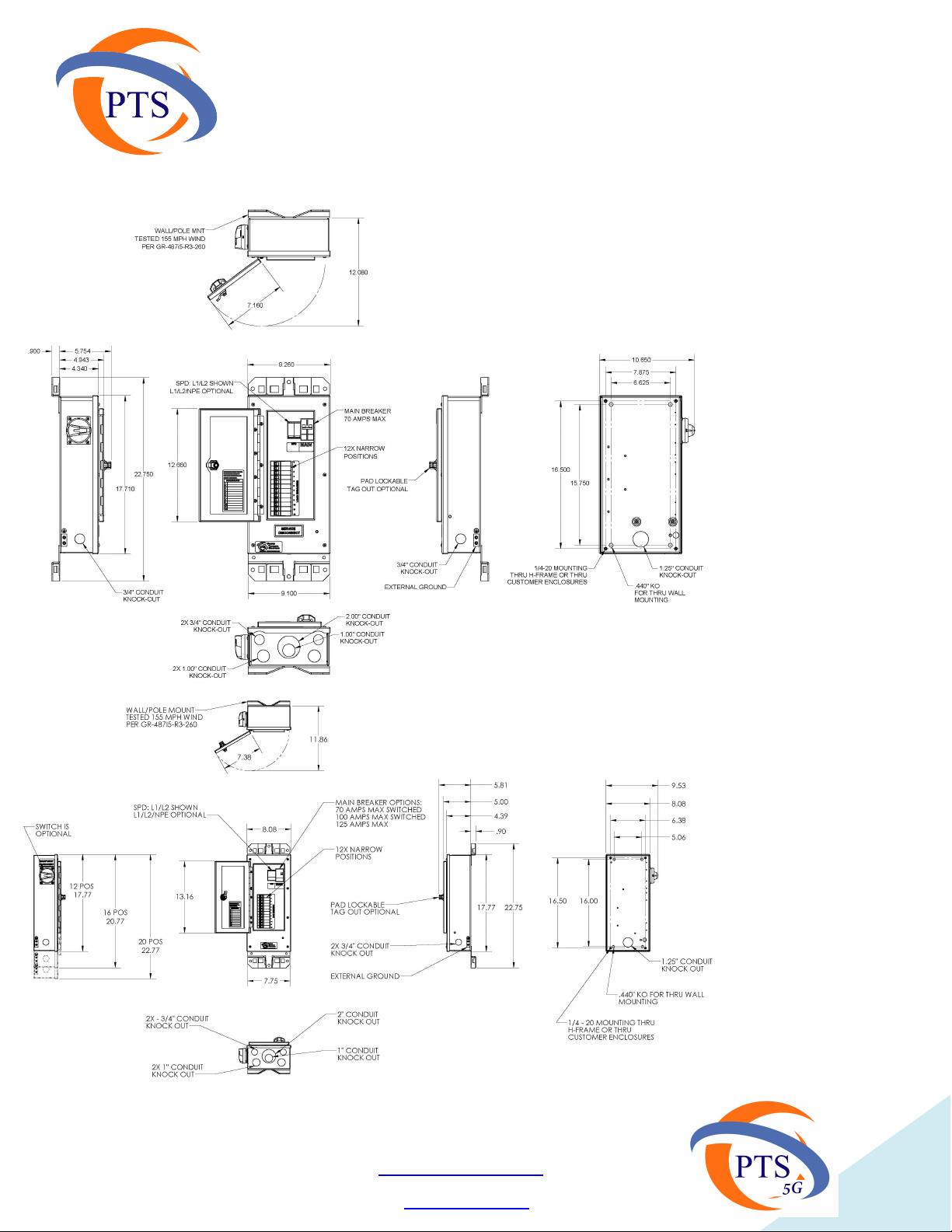
PTS9XX3X – Example of Dimensional Drawings
Figure 1:Example Dimensional Drawings
PTS9XX3X Series Small Cell
120/240V AC Power Distribution Load Centers
Installation Guide
All Rights Reserved, 2020
1-888-820-3508
www.pts5g.com
www.pactechsol.com
PTS92X3X Models
PTS90X3X Models

5
Caution: Installation shall be completed per allNEC and Local Codes. Do not install
PTS9000 Systems before reading and understanding allspecifications and installation
guides provided. Installation should be performed by a qualified installer.
1.1 Specifications
Electrical Specifications:
Panel Rating 120/208/240V AC
Phase Single Phase
Load Center Breakers (12, 14, 16, 20 Pos.) UL489
Load Center Input 2/0 – 14 awg, model specific
Breaker Connections 4 awg – 14awg
Approvals UL67, Type 3R
Mechanical Specifications:
Color Grey Standard
Size(in) 12 - 14pos 17.71 × 9.26 × 4.94
Weight(lbs) 12 to 16lbs
Temperature(℃) -40 to +40, above +40 see chart
Operating Humidity 5~95%
Ambient Derating of QOU Circuit Breaker
20.71 × 9.26 × 4.94
23.71 × 9.26 × 4.94
Size(in) 16 pos
Size(in) 20 pos
PTS9XX3X Series Small Cell
120/240V AC Power Distribution Load Centers
Installation Guide
All Rights Reserved, 2020
1-888-820-3508
www.pts5g.com
www.pactechsol.com

6
Caution: Installation shall be completed per allNEC and Local Codes. Do not install
PTS9000 Systems before reading and understanding allspecifications and installation
guides provided. Installation should be performed by a qualified installer.
Breaker Load Out Examples:
PTS9XX3X Series Small Cell
120/240V AC Power Distribution Load Centers
Installation Guide
All Rights Reserved, 2020
1-888-820-3508
www.pts5g.com
www.pactechsol.com

7
1.3 Application
The PTS9XX3X are compact 120V/208V/240V AC Load Centers designed for Small Cell, Pico,
Micro, CRAN and Macro Deployments where distribution of AC power is required.
The PTS9XX3X Series of compact AC Load Centers can also be used for AC Power Distribution
applications where limited space exists, excluding the ability to use a larger load center.
The PTS9XX3X Series are Suitable for Use as Service Equipment.
The PTS9XX3X Series of compact AC Load Centers can also be used as a sub-tending branch
panel when modernizing or expanding existing sites.
The PTS9XX39Series options include an external rotary disconnect switch, allowing for the
utility, fire safety and first responders to quickly and safely disconnect power.
2.0 Features
The PTS9XX3X Series of Small Cell AC Load Centers support a customer specific
configuration, ready for install in new or expansion environments.
2.1 Main Breaker
The PTS9XX3X Systems can support a QOU main breaker with Ampacity from 70A to
125Amps, either in Single Pole 120VAC, or Dual Pole 208V/240VAC.
The main breaker temperature de-rating chart is found on page 6
2.2 Distribution Breakers
The PTS90X3XSystemshave 12UL489 Breaker positions
The PTS91X3X Systems have 16 UL489 Breaker positions
The PTS92X3X Systems have 12, 16 or 20 UL489 Breaker positions
2.3 Optional SPD Protection
Single SPD (L1-N and L2-N) or a Dual SPD (L1-N, L2-N and N-PE)
2.4 Optional External Disconnect Switch
The PTS9XX36 Series does not include the external rotary disconnect switch and can support
up to 125 Amps
The PTS9XX39 Series includes an external rotary disconnect switch and can support up to
100 Amps.
PTS9XX3X Series Small Cell
120/240V AC Power Distribution Load Centers
Installation Guide
All Rights Reserved, 2020
1-888-820-3508
www.pts5g.com
www.pactechsol.com

8
3.0 Inspecting and Unpacking
3.0.1 Inspect the packaging for obvious signs of rough handling and/or external damage.
3.0.2Review Installation Guide.
3.0.3Remove from plastic packaging.
4.0 Installation
The PTS9XX3XSystems are certified for outdoor installations.
This section provides installations guidelines toinsure the appropriate requirements are
met.
4.1.1 A mounting bracket isincluded and pre-installed along the top and bottom back edge of the
enclosure and can be used as a template, or mounting detail from specifications page can be used if
preferred.
4.1.2 If mounting bracketisreplaced,a lock-tite like adhesiveshould be applied to
the screw threads and tighten according to specifications.
4.2 Mount enclosure vertically on surfaces
4.2.1To maintain 3R Rating, the enclosure must be mounted vertically, do not make
holes in top or sides, and use only raintight connectors
4.2.2 Customer isresponsible to identify suitable location for mounting.
4.2.3Mark and drill anchors or clips to secure enclosure to surface or pole
4.2.4Torque to mounting hardware specifications.
4.3 Removing Front Door / Access Cover
4.3.1 Locate Front Door / Access Cover set screwsand remove
4.3.2 Set aside for reuse.
4.3.3 Review Equipment Ground Connection Points
4.3.4 Review Neutral Connection Points
4.1 Mounting Bracket
4.0.1To maintain 3R Rating, the enclosure must be mounted vertically,
4.0.2 Do not make holes in top or sides where internal parts restrict access.
4.0.3 Use only raintight connectors
4.0.4 Panelboard intended to be field installed on a utility pole, street pole, shelter or flat surface
suitable for installation per building code where applicable.
PTS9XX3X Series Small Cell
120/240V AC Power Distribution Load Centers
Installation Guide
All Rights Reserved, 2020
1-888-820-3508
www.pts5g.com
www.pactechsol.com
9
4.4 Wiring Ground Connections
4.4.1 Ensure enclosure is grounded as per NEC and Local Jurisdictions Code requirements.
4.4.2 Ensure that the neutral bussbar isgrounded per NEC and Local Jurisdictions Code
if required.
4.4.3 Tighten connections asper manufacturers specifications.
Figure 3: Location of External Enclosure Ground Connection
Lower Left or Right Side on PTS9000 Series Enclosures
Caution: Installation shall be completed per allNEC and Local Codes. Do not install
PTS9000 Systems before reading and understanding allspecifications and installation
guides provided. Installation should be performed by a qualified installer.
PTS9XX3X
120/240V AC Power Distribution Load Centers
Installation Guide
All Rights Reserved, 2020
1-888-820-3508
www.pts5g.com
www.pactechsol.com

10
4.5 Wiring Service and Load Connections
4.5.1 Wiring tobe done in accordance with NEC and Local Jurisdictions Code.
4.5.1.1.Field conductors should be 70C copper minimum.
4.5.1.2 See QOU Breaker derating chart for proper operating ampacity on page 6.
4.5.2 Wire the Service Ground to the internal ground bar
4.5.3 Wire the Service Neutral to Neutral bar connection according to use and Local
Jurisdictional Code.
4.5.4 If wiring for Service Entrance, ensure that the provided bond wiring strap is connected
between the internal ground bar and neutral bar, and label accordingly as per 4.5.11.1
below.
4.5.5Wire the Service Feed to the bottom side (service side) of the Main Breaker (s)
4.5.6Land Equipment ground to ground bar
4.5.7Land Equipment Neutral to Neutral bar
4.5.8Land Load feeds to the right side (load side) ofload breaker(s)
4.5.9Ensure connections are properly seated in set screw capture ring openings prior to
tightening per specifications.
4.5.10 Tighter per breaker and bar specifications
4.5.11Ensure allbreakers are labeled
4.5.11.1 If installed as Service Equipment, apply the "SERVICE DISCONNECT" label at the
primary breaker positions
4.5.11.2 If installed as Branch Equipment, apply the "MAIN DISCONNECT" label at the
primary breaker positions
4.5.12Label Load Breakers accordingly
4.5.13If completed, re-install the front cover.
4.5.14 Tighten screws to 17 - 18 inch pounds
Caution: Installation shall be completed per allNEC and Local Codes. Do not install
PTS90000 Systems before reading and understanding allspecifications and installation
guides provided. Installation should be performed by a qualified installer.
PTS9XX3X Series Small Cell
120/240V AC Power Distribution Load Centers
Installation Guide
All Rights Reserved, 2020
1-888-820-3508
www.pts5g.com
www.pactechsol.com

11
Figure 4: Standard Wiring Space Example
Caution: Installation shall be completed per allNEC and Local Codes. Do not install
PTS90000 Systems before reading and understanding allspecifications and installation
guides provided. Installation should be performed by a qualified installer.
PTS9XX3X Series Small Cell
120/240V AC Power Distribution Load Centers
Installation Guide
All Rights Reserved, 2020
1-888-820-3508
www.pts5g.com
www.pactechsol.com

12
Figure 5:PTS9XX39 Series External Disconnect Switch
Location ( Yellow/Red Rotary Switch)
with Tag Out / Lock Out ( White Tab) Function
Caution: Installation shall be completed per allNEC and Local Codes. Do not install
PTS9000 Systems before reading and understanding allspecifications and installation
guides provided. Installation should be performed by a qualified installer.
PTS9XX3X Series Small Cell
120/240V AC Power Distribution Load Centers
Installation Guide
All Rights Reserved, 2020
1-888-820-3508
www.pts5g.com
www.pactechsol.com

13
5.0 Installation Review
Inspect the installation, verifying that all is in accordance with this document, NEC, and local Codes.
Caution: Installation shall be completed per allNEC and Local Codes. Do not install
PTS9000 Systems before reading and understanding allspecifications and installation
guides provided. Installation should be performed by a qualified installer.
PTS9XX3X Series Small Cell
120/240V AC Power Distribution Load Centers
Installation Guide
All Rights Reserved, 2020
1-888-820-3508
www.pts5g.com
www.pactechsol.com

14
6.0 Document and Revision Control
Author Tom Cooleen
Date 11/15/2019
File Location www.pactechsol.com
Revision Control
Issue Number 20
Date 10/11/2020
Description PTS9XX3X Series Installation Guide
Prime Contact 1
Name
Email
Phone
Department / Responsibility
Prime Contact 2
Name
Email
Phone
Department / Responsibility
Prime Contact 3
Name
Email
Phone
Department / Responsibility
PTS9XX3X Series Small Cell
120/240V AC Power Distribution Load Centers
Installation Guide
All Rights Reserved, 2020
1-888-820-3508
www.pts5g.com
www.pactechsol.com
This manual suits for next models
2
Table of contents
Other Pts Power Distribution Unit manuals


Popular Power Distribution Unit manuals by other brands


Siemens
Siemens SIPROTEC 7RW600 instruction manual

ABB
ABB Relion 670 series Applications manual

Compaq
Compaq 207590-B21 - Power Distribution Unit Strip Quick install guide

Gude
Gude Expert PDU Energy 8311 Series manual

Ormazabal
Ormazabal cgm.3 system Series General instructions

LEGRAND
LEGRAND Mosaic 775 40 quick start guide

Siemens
Siemens SIVACON 8PS BD2 Series installation instructions

S&C
S&C IntelliRupter PulseCloser manual

SIMARINE
SIMARINE CARAVAN SPDU-52 user manual

SLX
SLX 27874QR user guide

Keysight Technologies
Keysight Technologies 85309B LO/IF User's and service guide

Littelfuse
Littelfuse MiniFlec Series Installation sheet