InHand InVehicle T310 User manual

Version: V1.0
Date: Aug 2020
InVehicle T310 Tracker
Quick Start
1. Packing List
Standard packing list:
Optional parts:
2. Supported Vehicle Models
Dongfeng Kinland BAIC Auman (BJ4259SNHKB-AA) Iveco (NJ1045EFCS)
Dongfeng Tianjin Iveco (NJ6725DC) Iveco (NJ6605DC)
Sinotruk Howo Iveco (NJ6605DC) Yutong Heavy Industries
BAIC Foton
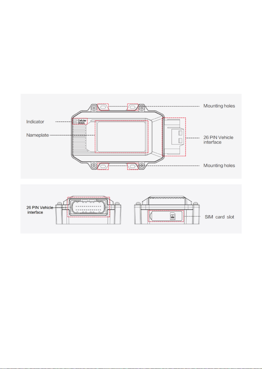
3. Appearance
4. Installation
For general use, insert a SIM card to the device, plug the cable, and install the device in the vehicle.
1) Inserting the SIM card
Insert the SIM card if you use dial-up to access the Internet. When the device is powered on, it
automatically accesses the Internet through dial-up. Remove the water guard from the side of VT310 and
insert the SIM card as shown in the following figure.
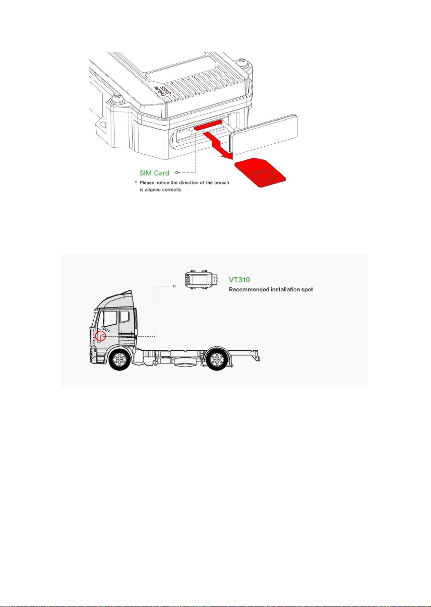
2) Installing the device
Use bolts to mount VT310 onto the vehicle. It is recommended to install it under the front windshield to
ensure stable GPS signal receiving and easy connection to the OBD-II diagnosis interface of the vehicle.
3) Connecting the cable
Three types of cables are provided for different scenarios. Their connection methods are as follows:
1. 26-pin all-in-one test cable:
Suitable for indoor testing, and a 9-48 V adapter is required.
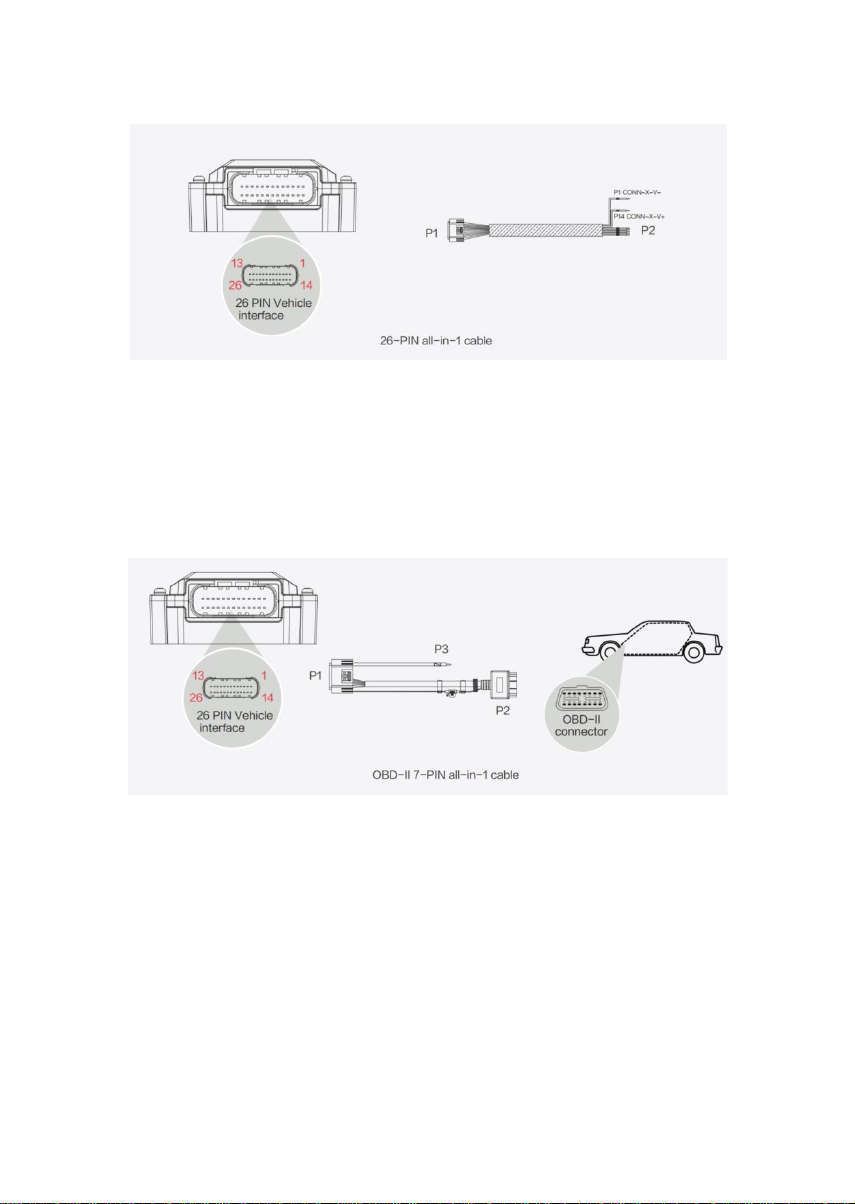
Procedure:
(1)
Connect the 26-pin socket at the P1 end to the VT310 interface.
(2)
Connect CONN-X-V- and CONN-X-V+ at the P2 bare wire end to the negative pole and positive pole
of the power adapter respectively.
2. OBD-II 7-pin all-in-one test cable:
Suitable for heavy trucks with the OBD-II diagnosis interface. VT310 is powered by the diagnosis interface,
so you need to start the vehicle before using it.
Procedure:
(1)
Connect the 26-pin socket of the P1 end to the VT310 interface.
(2)
Connect P2 to the OBD-II diagnosis interface of the vehicle.
(3)
To check whether the vehicle has started, connect P3 to the ignition switch of the vehicle.
3. OBD-II 26-pin all-in-one test cable:
Suitable for heavy trucks with the OBD-II diagnosis interface. VT310 is powered by the diagnosis interface,
so you need to start the vehicle before using it. Compared with the OBD-II 7-pin all-in-one test cable, this
cable provides a 19-pin I/O bare wire end. It is recommended to use this cable if I/O or 1-Wire hardware is
used.

Procedure:
(1)
Connect the 26-pin socket of the P1 end to the VT310 interface.
(2)
Connect P2 to the OBD-II diagnosis interface of the vehicle.
(3)
To check whether the vehicle has started, connect P3 to the ignition switch of the vehicle.
(4)
You can connect the P4 bare wire end to the I/O device as required. For details, see the following
section.
4) Connecting the I/O interface
The I/O interface is integrated in the 26-pin vehicle-mounted interface and provides three digital output
channels with a maximum current of 300 mA, four digital input channels, one analog input channel, one 1-
Wire channel, one RS232 serial port, and one ignition signal channel. Here are some examples of I/O
interface connection.
Definition of the 26-pin vehicle-mounted interface:
Pin
Terminal
Pin
Terminal
Pin
Terminal
Pin
Terminal
1
V-
8
1-Wire
14
V+
21
GND
2
GND
9
RS232_RX
15
IGT
22
RS232_TX
3
DI2
10
GND
16
DI1
23
GND
4
DI4
11
CAN_1L
17
DI3
24
CAN_1H
5
GND
12
CAN_2L
18
GND
25
CAN_2H
6
DO2
13
J1708_B
19
DO1
26
J1708_A
7
AI
20
DO3
1. RS232 serial port:
The RS232 serial port is used for debugging. Before using it, connect the RS232_RX, RS232_TX, and
GND terminals of VT310 to the TXD, RXD, and GND terminals of the DB-9 serial port connector
respectively, and then use an RS232-to-USB adaptation cable to connect to the DB-9 serial port
connector.
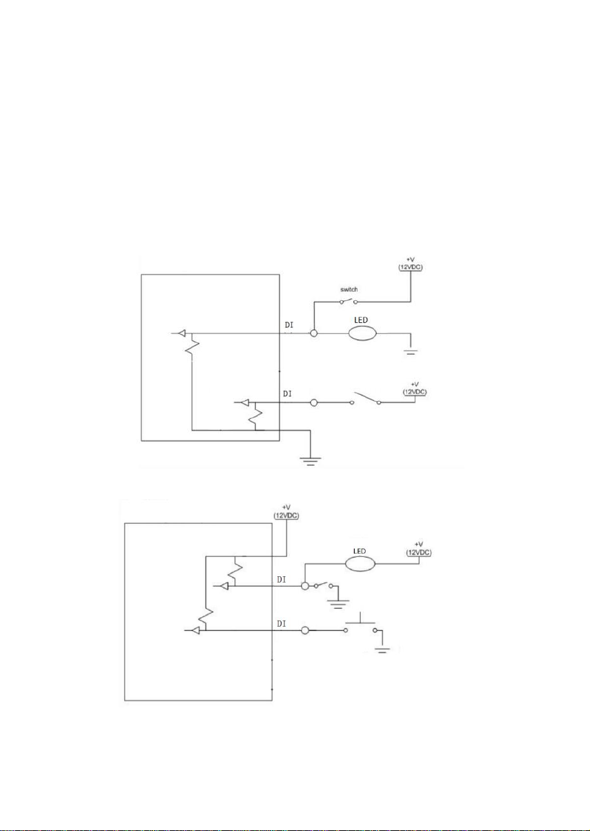
2. Digital input (DI for short):
DI can detect the switch status, for example, whether the button is pressed down and whether the switch
is in the ON or OFF position. VT310 supports configurable pull-up resistance. By default, DI has 10 kΩ of
resistance pulled down to GND. When pull-up resistance is configured for DI, 20 kΩ of resistance is pulled
up to the power voltage. When using DI, you need to determine whether pull-up resistance is used.
The following figure shows the external circuit when pull-up resistance is not used for DI:
The following figure shows the external circuit when pull-up resistance is used for DI:
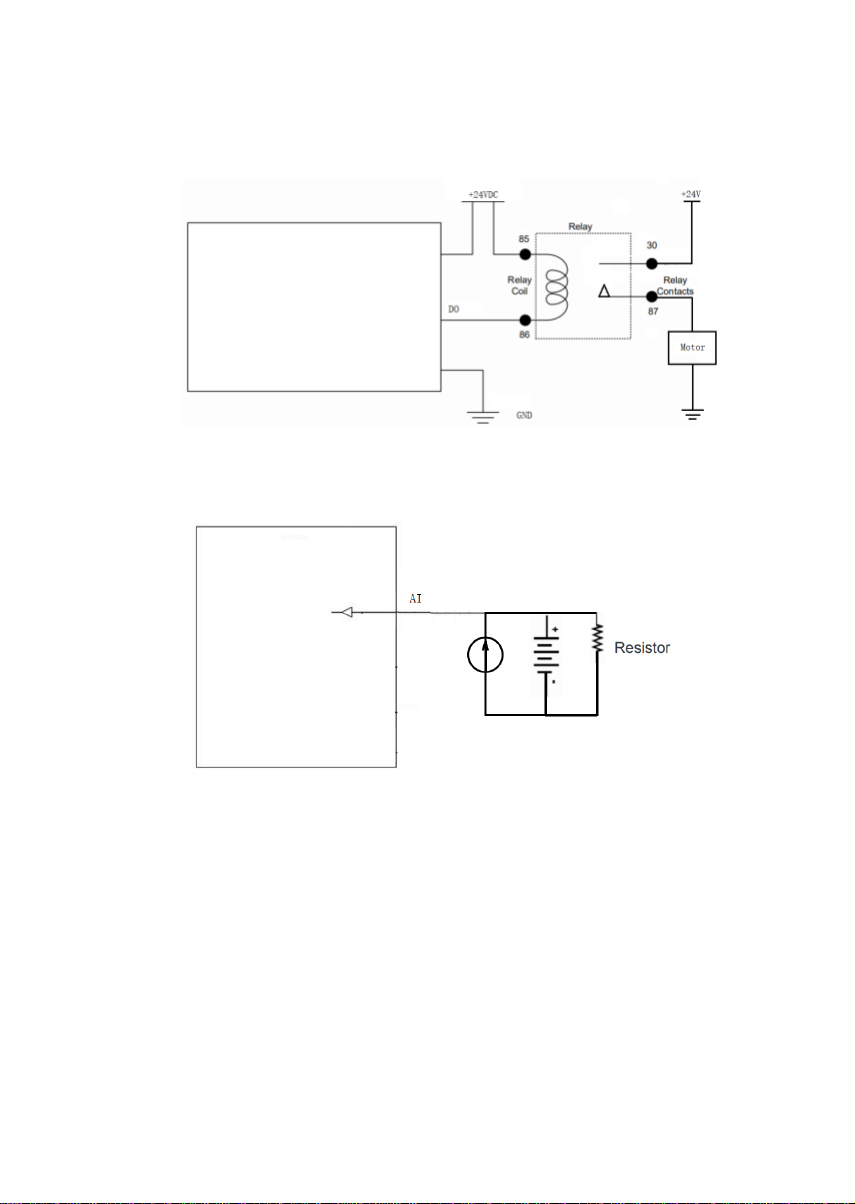
3. Digital output (DO for short):
DO can output DC voltage. DO is open-drain output and supports up to 300 mA of current. It is generally
used with a relay.
4. Analog input (AI for short):
AI can detect DC voltage, so you can input analog voltage values. The following figure shows the external
circuit when AI is used:
5. 1-Wire:
1-Wire is generally used with small communication devices, such as digital thermometers and iButton
devices. Before using it, you need to connect the DQ pin to pin 8 of VT310 and the VDD and GND pins to
the GND pin of VT310.
6. Ignition sense (IGT for short):
IGT is connected to the ignition switch of the vehicle, so that VT310 can detect whether the vehicle is
started.
5. Device Startup
You can start the device for debugging after the preceding steps. You can check the device status
according to the indicators. To avoid battery power loss during transport, the VT310 is set in transport
mode by factory settings. You need to activate it with an external power supply or through the diagnosis
interface of the vehicle.

1) GNSS indicator
Indicator Status
Function Status
Off
The device is not started, or GNSS is disabled.
Quick blinking at 0.5 Hz
GNSS timing is successful.
Slow blinking at 1 Hz
GNSS is enabled.
Remains on
Positioning is successful.
2) Cellular indicator
Indicator Status
Function Status
Off
The device is not started, or dial-up is disabled.
Quick blinking at 0.5 Hz
Dial-up is successful.
Slow blinking at 1 Hz
Dial-up is enabled.
Table of contents
Other InHand GPS manuals


