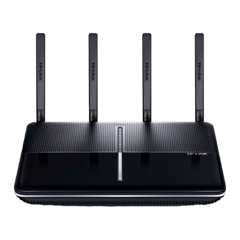
InHand CR202 User manual

InHand Networks CR202 Portable 4G Router
User Manual
Issue: V1.0—March, 2023

Declaration
Thank you for choosing our product. Before using the product, read this manual carefully.
The contents of this manual cannot be copied or reproduced in any form without the written
permission of InHand.
Due to continuous updating, InHand cannot promise that the contents are consistent with the
actual product information, and does not assume any disputes caused by the inconsistency of
technical parameters. The information in this document is subject to change without notice.
InHand reserves the right of final change and interpretation.
© 2020 InHand Networks. All rights reserved.
Conventions
Symbol
Indication
< >
Content in angle brackets “<>” indicates a button name. For example, the <OK> button.
""
'''' indicates a window name or menu name. For example, the pop-up window "New
User."
>
A multi-level menu is separated by the double brackets ">". For example, the
multi-level menu File > New > Folder indicates the menu item [Folder] under the
sub-menu [New], which is under the menu [File].
Cautions
Means reader be careful. Improper action may result in loss of data or device damage.
Note
Notes contain detailed descriptions and helpful suggestions.
Contact Us
43671 Trade Center Place, Suite 100, Dulles, VA20166
E-mail: support@inhandneworks.com
T: +1 (703) 348-2988
URL: www.inhandnetworks.com

Contents
I. INTRODUCTION................................................................................................................................. 1
1.1 OVERVIEW.................................................................................................................................... 1
1.2 PANELINTRODUCTION............................................................................................................. 2
1.3 LED INDICATION &SIGNAL ...................................................................................................... 2
1.4 RESET TO DEFAULT SETTINGS........................................................................................................... 2
II. INSTALLATION.................................................................................................................................. 4
2.1 PREPARATIPNS............................................................................................................................ 4
2.2 INSTALLATION............................................................................................................................ 4
2.2.1 SIM/UIM Card ........................................................................................................................ 4
2.2.2 Antenna.................................................................................................................................... 5
2.2.3 Power Supply........................................................................................................................... 6
2.3 LOGIN ROUTER ........................................................................................................................... 6
III. WEB CONFIGURATION .................................................................................................................. 8
3. 1SYSTEM........................................................................................................................................ 8
3.1.1 Basic Setup.............................................................................................................................. 8
3.1.2 System Time............................................................................................................................ 8
3.1.3 Admin Access.......................................................................................................................... 9
3.1.4 System Log.............................................................................................................................11
3.1.5 Configuration Management....................................................................................................11
3.1.6 Scheduler............................................................................................................................... 12
3.1.7 Upgrade ................................................................................................................................. 13
3.1.8 Reboot.................................................................................................................................... 13
3.1.9 Logout.................................................................................................................................... 13
3.2 NETWORK................................................................................................................................... 13
3.2.1 CELLULAR .......................................................................................................................... 13
3.2.2 WAN/LAN Switch................................................................................................................. 15
3.2.3 LAN....................................................................................................................................... 18
3.2.4 Switch WLAN Mode............................................................................................................. 18

3.2.5 WLAN Client (AP Mode) ..................................................................................................... 19
3.2.6 WLAN Client (STA Mode) ................................................................................................... 19
3.2.7 IP Passthrough....................................................................................................................... 20
3.2.8 Static Route ........................................................................................................................... 21
3.3 SERVICES.................................................................................................................................... 21
3.3.1 DHCP Service........................................................................................................................ 21
3.3.2 DNS....................................................................................................................................... 22
3.3.3 DNS Relay............................................................................................................................. 23
3.3.4 DDNS.................................................................................................................................... 24
3.3.5 Device Manager..................................................................................................................... 25
3.3.6 SMS....................................................................................................................................... 26
3.3.7 Traffic Manager..................................................................................................................... 26
3.3.8 Alarm Settings ....................................................................................................................... 27
3.3.9 User Experience Plan ............................................................................................................ 27
3.4 FIREWALL................................................................................................................................... 27
3.4.1 Basic...................................................................................................................................... 28
3.4.2 Filtering ................................................................................................................................. 28
3.4.3 Device Access Filtering......................................................................................................... 29
3.4.4 Content Filtering.................................................................................................................... 29
3.4.5 Port Mapping......................................................................................................................... 30
3.4.6 Virtual IP Mapping ................................................................................................................ 30
3.4.7 DMZ...................................................................................................................................... 31
3.4.8 MAC-IP Binding ................................................................................................................... 31
3.4.9 NAT ....................................................................................................................................... 32
3.5 QOS............................................................................................................................................... 32
3.5.1 IP BW Limit .......................................................................................................................... 33
3.6TOOLS.......................................................................................................................................... 33
3.6.1 PING...................................................................................................................................... 33
3.6.2 Traceroute.............................................................................................................................. 34
3.6.3 Link Speed Test..................................................................................................................... 34

3.6.4 TCPDUMP............................................................................................................................ 34
3.8APPLICATION............................................................................................................................. 34
3.8.1 SMBC.................................................................................................................................... 35
3.9 STATUS........................................................................................................................................ 35
3.9.1 System ................................................................................................................................... 35
3.9.2 Modem................................................................................................................................... 35
3.9.3 Traffic Statistics..................................................................................................................... 35
3.9.4 Alarm..................................................................................................................................... 36
3.9.5 WLAN................................................................................................................................... 36
3.9.6 Network Connections............................................................................................................ 36
3.9.7 Device Manager..................................................................................................................... 37
3.9.8 Route Table............................................................................................................................ 37
3.9.9 Device List............................................................................................................................. 37
3.9.10 Log....................................................................................................................................... 37
3.9.11 Third Party Software Notices.............................................................................................. 38
APPENDIXA FAQ................................................................................................................................. 39
APPENDIX B INSTRUCTION OF COMMAND LINE....................................................................... 41

1
I. INTRODUCTION
1.1 OVERVIEW
The mobile 4G cellular router CR202 greatly increases the access flexibility in remote
office/study, mobile scenarios, and field scenarios with a reliable Internet connectivity. It can also
guarantee a smooth business operation for small and medium-sized branches and self-service
terminal scenarios and avoid any network failure may exist.
CR202 supports wired networks to wireless access, which increases the diversity of device access
to the network and can effectively ensure that the network is not interrupted. The powerful built-in
battery also allows you to work anytime and anywhere. With the lightweight design, it allows for
unrestricted device mobility.
Combined with InHand Device Manager cloud management platform, CR202 guarantees efficient
device management capabilities, provides customers with high-speed network access, simple and
convenient network management services to empower the core network.

2
1.2 PANEL INTRODUCTION
1.3 LED INDICATION &SIGNAL
CR202 LED
Status
System
Off --- Power off
Blink in green --- Device starting
Steady in green --- Device working
Blink in yellow --- Upgrading
Network
Off --- Cellular disable
Blink in green --- Dialing up
Blink in yellow --- Dialing abnormal
Blink in red --- No SIM card, cannot read SIM card or modem abnormal
Steady in green --- Dialed up, signal level≥20
Steady in yellow --- Dialed up, 19≥signal level≥10
Steady in red --- Dialed up, 9≥signal level
Wi-Fi
Off --- Wi-Fi disable
Blink in green --- Wi-Fi connected, data transmitting
Steady in green --- Wi-Fi enable
Battery
Blink --- Battery charging
Steady --- Battery discharging
Green --- 80%<battery level ≤100%
Yellow --- 20%<battery level ≤80%
Red --- 0<battery level ≤20%
1.4 Reset to default settings

3
To restore to default settings via the reset button, please perform the following steps:
1. Press the RESET button immediately after power on the device.
2. When System LED is steady on, release RESET button, system LED will blink, and press the
RESET button again.
4. When System LED blinks slowly, release the RESET button. The device has been restored to
default settings and will start up normally later.

4
II. INSTALLATION
2.1 PREPARATIPNS
Precautions:
Please be sure there is 3G/4G network coverage. Avoid direct sunlight, away from heat source or
strong electromagnetic interference. First installation shall be done under direction of the engineer
recognized by InHand Networks.
•1 PC
OS: Windows 7, Windows 10, Windows 11
Ethernet port: At least one (10M/100M)
•1 SIM card:
Ensure the card is enabled with data service and its service is not suspended
because of an overdue charge.
•Power supply:
5V/2A Type-C interface
Internal battery
•Fixation:
Please place CR202 on flat level and have it installed in an environment with small
vibrational frequency.
The device shall be installed and operated in powered-off status!
2.2 INSTALLATION
2.2.1 SIM/UIM Card
CR202 supports single nano SIM card or eSIM. Please install the SIM card like below if use nano

5
SIM card.
2.2.2Antenna
Slightly rotate the movable part of metal SMA-J interface until it cannot be rotated (at this time,
external thread of antenna cable cannot be seen). Do not forcibly screw the antenna by holding

6
black rubber lining.
2.2.3 Power Supply
CR202 supports internal battery or Type-C interface (5V/2A), please pay attention to the power
voltage level.
2.3 LOGIN ROUTER
Upon installation of hardware, be sure the Ethernet card has been mounted in the supervisory PC
prior to logging in the page of Web settings of the router.
I. AutomaticAcquisition of IPAddress (Recommended)
Please set the supervisory computer to "automatic acquisition of IP address" and "automatic
acquisition of DNS server address" (default configuration of computer system) to let the device
automatically assign IP address for supervisory computer.
II. Set a Static IPAddress
Set the IP address of supervisory PC (such as 192. 168. 2. 2) and LAN interface of device in same
network segment (initial IP address of LAN interface of device: 192. 168. 2. 1, subnet mask: 255.
255. 255. 0).

7
Automatic Acquisition of IPAddress (left) and Static IPAddress (right)
III. Cancel the Proxy Server
If the current supervisory PC uses a proxy server to access the Internet, it is required to cancel the
proxy service. The operating steps are shown below: 1) In the browser window, select
"tools>>Internet options"; 2) select "connection" page and click the button of LAN Settings to
enter "LAN Settings" window interface. Please confirm if the option "Use a Proxy Server for
LAN" is checked; if it is checked, please cancel and click the button <OK>.
IV. Log in/Exit Web Settings Page
Access to the default IP address 192.168.2.1 in a browser, enter username and password
(adm/123456 by default) in pop-up window and then access to router’s WEB management page. If
the browser alarms the connection is not private, show advanced, and proceed to access to the
address.
For security, please modify the default login password after the first login and keep the
password information.

8
III. WEB CONFIGURATION
The device need to be effectively configured before using. This chapter will introduce how to
configure your router via Web.
3. 1 SYSTEM
This part is used to check and configure system time, router WEB configuration interface,
language as well as the name of router.
3.1.1 Basic Setup
Check and set WEB configuration interface language and the name of router.
From the navigation tree, select System >> Basic Setup, then enter the “Basic Setup” page.
Table 3-1-1 Basic Setup Parameters
Basic settings
Function description: Select display language of the router web page and set personalized
name.
Parameters
Description
Default
Language
Configure language of WEB configuration interface
English
Host Name
Set a name for the host or device connected to the router
for viewing.
Router
3.1.2 System Time
To ensure the coordination between this device and other devices, it is required to set the system
time in an accurate way since this function is used to configure and check system time as well as
system time zone. System time page is used to configure and view system time and system time
zone.
From the navigation tree, select System >> Time, then enter the “Time” webpage, as shown below.
Click <Sync Time> to synchronize the time of the router with the system time of the PC.
Table 3-1-2 Parameters of System Time
System Time

9
Function description: Set local time zone and automatic updating time of NTP.
Parameters
Description
Default
Time of Router
Display present time of router
8:00:00 AM, 12/12/2015
PC Time
Display present time of PC
Present time
Timezone
Set time zone of router
Custom
Custom TZ String
Set TZ string of router
CST-8
Auto update Time
Select whether to automatically update
time, you may select when startup or
every 1/2/...hours.
On startup
NTPTime Servers
Select NTP server to synchronize time
1.pool.ntp.org
3.1.3 Admin Access
Admin services include HTTP, HTTPS, TELNET and SSHD.
HTTP
HTTP (Hypertext Transfer Protocol) is used for transferring web pages on Internet. After enabling
HTTP service on device, users can log on via HTTP and access and control the device using a web
browser.
HTTPS
HTTPS (Secure Hypertext Transfer Protocol) is the secure version of hypertext transfer protocol.
As a HTTP protocol which supports SSL protocol, it is more secure.
TELNET
Telnet protocol provides telnet and virtual terminal functions through a network. Depending on
Server/Client, Telnet Client could send request to Telnet server which provides Telnet services.
The device supports Telnet Client and Telnet Server.
SSHD
SSH protocol provides security for remote login sessions and other network services. The SSHD
service uses the SSH protocol, which has higher security than Telnet.
From the navigation tree, select System >> Admin Access, then enter “Admin Access” page.
Table3-1-3 Parameters of Admin Access
Admin Access
Function description:
1. Modify username and password of router.
2. The router can be accessed by the following 4 methods, http, https, telnet and SSHD.

10
3. Set login timeout.
Parameters
Description
Default
Username/Password
Username
Set name of user who logs in WEB configuration page
adm
Old
Password
Previous password access to WEB configuration page
New
Password
New password access to WEB configuration pagee
N/A
Confirm
New
Password
Reconfirm the new password
N/A
Amin functions
Service Port
Service port of HTTP/HTTPS/TELNET/SSHD
80/443/23/22
Local
Access
Enable - Allow local LAN to administrate the router
with corresponding service (e.g. HTTP)
Disable - Local LAN cannot administrate the router with
corresponding service (e.g. HTTP)
Enable
Remote
Access
Enable - Allow remote host to administrate the router
with corresponding service (e.g. HTTP)
Disable - Remote host cannot administrate the router
with corresponding service (e.g. HTTP)
Enable
Allowed
Access from
WAN
(Optional)
Set allowed access from WAN
Set the hosts which
are allowed to
access the router,
e.g. 192.168.2.1/30
or
192.168.2.1-192.1
68.2.10
Description
For recording significance of various parameters of
admin functions (without influencing router
configuration)
N/A
Non-privileged users
Username
Configure non-privileged login user name
N/A
Password
Configure the password of the non-privileged user
N/A
Other Parameters
Log
Timeout
Set login timeout (router will automatically disconnect
the configuration interface after login timeout)
500 seconds
⚫In “Username/Password” section, users can modify username and password rather than

11
create new username, i.e. only this username can be used in logins.
3.1.4 System Log
A remote log server can be set through “System Log”, and all system log will be uploaded to the
remote log server through Internet. This requires remote log software, in such as Kiwi Syslog
Daemon, on remote log server.
Kiwi Syslog Daemon is a free log server software for Windows, It can receive, record and display
logs from host (such as router, exchange board and Unix host). After downloading and installing
Kiwi Syslog Daemon, it must be configured through the menus “File >> Setup >> Input >> UDP.
From the navigation tree, select System >> System Log, then enter “System Log” page.
Table 3-1-4 Parameters of System Log
System Log
Function description: Configure IP address and port number of remote log server which will
record router log.
Parameters
Description
Default
Log to Remote System
Enable log server
Disable
Log server address and
port (UDP)
Set address and port of remote log server
N/A:
514
3.1.5 Configuration Management
Here you can back up the configuration parameters, import the desired parameters backup and
reset the router.
From the navigation tree, select “System >> Config Management”, then enter the “Config
Management” page.
Table 3-1-5 Parameters of Configuration Management
Configuration Management
Function description: Set parameters of configuration management.
Parameters
Description
Default
Browse
Choose the configuration file
N/A
Import
Import configuration file to router
N/A
Backup
Backup configuration file to host
N/A
Restore default
configuration
Select to restore default configuration (effective after
rebooting)
N/A

12
Disable the
hardware reset
button
Select to disable hardware reset button of the router
Disable
Network Provider
(ISP)
For configuring APN, username, password and other
parameters of the network providers across the world
N/A
Validity and order of imported configurations should be ensured. Acceptable configuration will
later be serially executed in order after system reboot. If the configuration files didn’t be
arranged according to effective order, the system won’t enter the desired state.
In order not to affect the operation of the current system, after performing an import
configuration and restore default configuration, please restart the device to make the new
configuration to take effect.
3.1.6 Scheduler
After this function is enabled, the device will reboot as the scheduled time. Scheduler function
will take effect after router sync time.
From the navigation tree, select “System >> Scheduler”, then enter “Scheduler” page.
Table 3-1-6 Parameters of Scheduler
Scheduler
Function description: set scheduler for system reboot
Parameters
Description
Default
Enable
Enable/disable this function
Disable
Time
Select the reboot time
0:00
Days
Reboot the router everyday
Everyday
Show advanced
options
Enable more detailed schedule rules, allow to set multiple
rules to reboot the router in specific time or interval.
Enable this feature will disable everyday reboot feature
above.
Disable
Reboot after dialed
Router will reboot after dial up successfully, will not take
effort if this parameter is blank.
N/A

13
3.1.7 Upgrade
The upgrading process can be divided into two steps. In the first step, firmware will be written in
backup file zone, in the second step: frimware in backup file zone will be copied to main firmware
zone, which should be carried out during system restart. During software upgrading, any operation
on web page is not allowed, otherwise software upgrading may be interrupted.
From the navigation tree, select “System >> Upgrade”, then enter the “Upgrade” page.
To upgrade the system, firstly, click <Browse> choose the upgrade file, secondly, click <Upgrade>
and then click <OK> to begin upgrade; thirdly, upgrade firmware succeed, and click <Reboot> to
restart the device.
3.1.8 Reboot
Please save the configurations before reboot, otherwise the configurations that are not saved will
be lost after reboot.
To reboot the system, please click the “System>>Reboot”, then click <OK>.
3.1.9 Logout
To logout, click “System >> Logout”, and then click <OK>.
3.2 NETWORK
3.2.1 CELLULAR
Insert SIM card and dial up to achieve the wireless network connection.
Click the “Network>>Cellular” in the navigation tree to enter Cellular configure page.
Table3-2-1-1 Parameters of Cellular
Cellular
Function description: Configure parameters of PPP dialup. Generally, users only need to set

14
basic configuration instead of advanced options.
Parameters
Description
Default
Enable
Enable Cellular dialup.
Enable
Time Schedule
Set time schedule
ALL
Force Reboot
Router will reboot if cannot dialup for a long
time and reach the max retry time
Enable
Shared connection
(NAT)
Enable—Local device connected to Router
can access to the Internet via Router.
Disable—Local device connected to Router
cannot access to the Internet via Router.
Enable
Default Route
Enable default route
Enable
SIM Network Provider
Select network provider for inserted SIM card
Profile 1
Network Select Type
Select network type, router will try 4G, 3G,
2G in proper order if select in Auto
Auto
Connection Mode
Optional Always Online, Connect On
Demand, Manual. It will support to configure
Triggered by SMS if select Connect On
Demand mode,
Always Online
Redial Interval
Set the redialing time when dial up fails.
30 s
Show Advanced Options
Dual SIM Enable
Some of CR202 types support eSIM, enable
this option to enable eSIM dial up
Disable
eSIM Network Provider
Select network provider for eSIM card
Profile 1
eSIM Blinding ICCID
Set ICCID of eSIM
N/A
eSIM PIN Code
For setting eSIM PIN code
N/A
eSIM SIM Card
Operator
Set the ISP that eSIM card connects to
Auto
Main SIM
Set the SIM card that uses to dialup at first
SIM
Max Number of Dial
Set max number of dial, if cannot dial up
successfully after this number, router will
switch SIM card
5
CSQ Threshold
Set threshold of signal, if current signal level
is lower than this, router will switch SIM card
0(Disable)
Min Connect Time
Set the min connect time for each try of dial
up
0(Disable)
Initial Commands
Set customize initial AT commands which
will be operated at the beginning of dialing up
AT
Blinding ICCID
Set ICCID of SIM
N/A
PIN Code
For setting PIN code of SIM
N/A
Static MTU
Set max transmission unit after enable
Disable
Use Peer DNS
Click to receive peer DNS assigned by the
ISP
Enable
Link detection interval
Set link detection interval
55 s

15
Debug
Enable debug mode
Disable
ICMP Detection Mode
Set ICMP detection mode, router will check
the link connection status via ICMP packet.
Ignore Traffic: Router will send ICMP packet
no matter whether there is traffic in cellular
interface.
Monitor Traffic: Router will not send ICMP
packet if there is traffic in cellular interface.
Ignore Traffic
ICMP Detection Server
Set the ICMP Detection Server. N/A
represents not to enable ICMP detection.
N/A
ICMP Detection
Interval
Set ICMP Detection Interval
30 s
ICMP Detection
Timeout
Set ICMP Detection Timeout (the link will be
regarded as down if ICMP times out)
20 s
ICMP Detection Retries
Set the max. number of retries if ICMP fails
(router will redial if reaching max. times)
5
Table 3-2-1-2 Parameters of Cellular - Schedule
Administration of Cellular - Schedule
Function description: Online or offline based on the specified time.
Parameters
Description
Default
Name
Name of Schedule
Schedule_1
Sunday ~ Saturday
Click to enable
Time Range 1
Set time range 1
9:00-12:00
Time Range 2
Set time range 2
14::00-18:00
Time Range 3
Set time range 3
0:00-0:00
Description
Set description content
N/A
3.2.2 WAN/LAN Switch
Click the “Network>>WAN/LAN Switch”to set WAN/LAN1 port.
When configure this port as WAN, CR202 supports three types of wired access including static IP,
dynamic address (DHCP) and ADSL (PPPoE) dialing. When configure this port as LAN, it
supports to jump to LAN configure page via Settings button on the right of the select box.
DHCP adopts Client/Server communication mode. Client sends configuration request to Server
which feeds back corresponding configuration information, including distributed IP address to the
Client to achieve the dynamic configuration of IP address and other information.
Table of contents
Other InHand Wireless Router manuals
