INIM Electronics F-COM User manual

1
Installation and User manual
F-COM
Telephone communicator
Installation and User manual
EN 54-2
EN 54-4
EN 54-21
0051
0051-CPR-1754
DCMIINIEFCOM-100-20190716

2
Telephone communicator
Warranty
INIM Electronics s.r.l. (Seller, Our, Us) warrants the original purchaser that this
product shall be free from defects in materials and workmanship under normal
use for a period of 24 months. As INIM Electronics s.r.l. does not install this
product directly, and due to the possibility that it may be used with other
equipment not approved by Us; INIM Electronics s.r.l. does not warrant against
loss of quality, degradation of performance of this product or actual damage that
results from the use of products, parts or other replaceable items (such as
consumables) that are neither made nor recommended by INIM Electronics. Seller
obligation and liability under this warranty is expressly limited to repairing or
replacing, at Seller's option, any product not meeting the specifications. In no
event shall INIM Electronics s.r.l. be liable to the purchaser or any other person for
any loss or damage whether direct or indirect or consequential or incidental,
including without limitation, any damages for lost profits, stolen goods, or claims
by any other party caused by defective products or otherwise arising from the
incorrect or otherwise improper installation or use of this product.
This warranty applies only to defects in parts and workmanship relating to normal
use. It does not cover:
• damage arising from improper maintenance or negligence
• damage caused by fire, flood, wind or lightning
•vandalism
• fair wear and tear
INIM Electronics s.r.l. shall, at its option, repair or replace any defective products.
Improper use, that is, use for purposes other than those mentioned in this manual
will void the warranty. Contact Our authorized dealer, or visit our website for
further information regarding this warranty.
Limited
warranty
INIM Electronics s.r.l. shall not be liable to the purchaser or any other person for
damage arising from improper storage, handling or use of this product.
Installation of this Product must be carried out by qualified persons appointed by
INIM Electronics. Installation of this Product must be carried out in accordance
with Our instructions in the product manual.
Copyright
The information contained in this document is the sole property of INIM
Electronics s.r.l. No part may be copied without written authorization from INIM
Electronics s.r.l.
All rights reserved.

3
Installation and User manual
Table of
contents
Warranty . . . . . . . . . . . . . . . . . . . . . . . . . . . . . . . . . . . . 2
Limited warranty. . . . . . . . . . . . . . . . . . . . . . . . . . . . . . . 2
Copyright . . . . . . . . . . . . . . . . . . . . . . . . . . . . . . . . . . . . 2
Table of contents . . . . . . . . . . . . . . . . . . . . . . . . . . . . . . 3
Chapter 1 General information. . . . . . . . . . . . . . . . . . . . . . . . . . . . . 5
1-1 Manufacturer's details. . . . . . . . . . . . . . . . . . . . . . . . . . . . . . . . . . . . . 5
1-2 About this manual . . . . . . . . . . . . . . . . . . . . . . . . . . . . . . . . . . . . . . . 5
1-3 Included documents . . . . . . . . . . . . . . . . . . . . . . . . . . . . . . . . . . . . . . 5
Chapter 2 Device description. . . . . . . . . . . . . . . . . . . . . . . . . . . . . . 6
2-1 Unpacking the box . . . . . . . . . . . . . . . . . . . . . . . . . . . . . . . . . . . . . . . 6
2-2 Technical description . . . . . . . . . . . . . . . . . . . . . . . . . . . . . . . . . . . . . 7
2-3 CE Mark . . . . . . . . . . . . . . . . . . . . . . . . . . . . . . . . . . . . . . . . . . . . . . 9
Chapter 3 Installation. . . . . . . . . . . . . . . . . . . . . . . . . . . . . . . . . . . 10
3-1 Wall-mounting . . . . . . . . . . . . . . . . . . . . . . . . . . . . . . . . . . . . . . . . . . 10
3-2 Connecting the switching power supply. . . . . . . . . . . . . . . . . . . . . . . . . 10
3-3 Mounting the Antenna . . . . . . . . . . . . . . . . . . . . . . . . . . . . . . . . . . . . 12
3-4 Telephone connections . . . . . . . . . . . . . . . . . . . . . . . . . . . . . . . . . . . . 12
3-5 Connecting to a PC. . . . . . . . . . . . . . . . . . . . . . . . . . . . . . . . . . . . . . . 13
3-6 Connecting the terminals . . . . . . . . . . . . . . . . . . . . . . . . . . . . . . . . . . 13
Chapter 4 First startup . . . . . . . . . . . . . . . . . . . . . . . . . . . . . . . . . . 18
4-1 Guided programming (initial setup wizard) . . . . . . . . . . . . . . . . . . . . . . 18
Chapter 5 Using the communicator . . . . . . . . . . . . . . . . . . . . . . . . . 20
5-1 Users . . . . . . . . . . . . . . . . . . . . . . . . . . . . . . . . . . . . . . . . . . . . . . . . 20
5-2 User interface . . . . . . . . . . . . . . . . . . . . . . . . . . . . . . . . . . . . . . . . . . 20
5-3 Language used by the user interface . . . . . . . . . . . . . . . . . . . . . . . . . . 22
5-4 Signals on the display. . . . . . . . . . . . . . . . . . . . . . . . . . . . . . . . . . . . . 23
5-5 Main menu . . . . . . . . . . . . . . . . . . . . . . . . . . . . . . . . . . . . . . . . . . . . 24
Appendix A Events . . . . . . . . . . . . . . . . . . . . . . . . . . . . . . . . . . . . . . 25
Appendix B Simplified declaration of conformity. . . . . . . . . . . . . . . . . . 28
WEEE. . . . . . . . . . . . . . . . . . . . . . . . . . . . . . . . . . . . . . . 31

4
Telephone communicator

General information 5
Installation and User manual
Chapter 1
GENERAL INFORMATION
1-1Manufacturer's details
Manufacturer: INIM Electronics s.r.l.
Production plant: Centobuchi, via Dei Lavoratori 10
Comune: 63076, Monteprandone (AP), Italy
Tel.: +39 0735 705007
Fax: +39 0735 704912
e-mail: [email protected]
Web: www.inim.biz
The persons authorized by the manufacturer to repair or replace the parts of this
system have authorization to work on INIM Electronics brand devices only.
1-2About this manual
Manual code: DCMIINIEFCOM
Revision: 1.00
1-3Included documents
• Installation and User manual (this manual)
• Programming manual
The manuals are supplied with the apparatus and can be downloaded from the
“Download” section of the Website: www.inim.biz. The installation manual is
included in the package. To order further copies contact the offices at INIM
Electronics.

6Device description
Telephone communicator
Chapter 2
DEVICE DESCRIPTION
The F-COM is a universal autonomous telephone communicator, certified in
accordance with EN 54-21 and EN 54-4 standards. It is to be used with fire
detection control panels manufactured both by Inim Electronics and other
manufacturers.
It is capable of operating as:
• fire alarm transmission device (device E for EN 54-1)
• fault signal transmission device (device J for EN 54-1)
The communicator operates autonomously:
• It detects control panel alarm and fault events through input terminals, as
well as its own internal events.
In Appendix A you can find the complete list of events generated.
• Activates programmable outputs.
• Makes voice calls over the PSTN line or GSM mobile network.
The default voice messages can be replaced by recorded custom messages.
• Sends digital messages using Contact ID protocol (over the PSTN line or GSM
mobile network) and SIA-IP (over mobile data network).
• Sends SMS messages over GSM network.
The default messages can be replaced by custom text messages.
• Provides communication feedback through the ALARM ACK output terminal
and LED signals.
ATTENTION!
INIM does not ensure full availability of all the GSM functions described in this
manual for the various combinations of GSM service provider, SIM type and
telephone set used.
2-1Unpacking the box
The device is packed in a cardboard box which contains:
• The F-COM inside its metal enclosure
• A bag containing the installation kit comprising:
- 3 x 3k9 Ohm 1/4W resistors
- 5 x 100 Ohm 1/4W resistors
- 1 x 1500 Ohm 1/4 W resistor
-1jumper
- battery connection wires
-thermalprobe
- ring terminal for the connection to Ground
•Antenna
• Installation manual (this manual)
The installation kit does not include:
• 12V 1.3A/h batteries
•SIMCard
Note
Be sure to have these items on hand before starting the installation procedure.

Device description 7
Installation and User manual
2-2Technical description
A2
A2
A2
A2
A2
A2
A2
A2
A2
A2
A2
A2
A2
A2
A2
A2
A2
A2
A2
A2
A2
A2
A2
A2
A2
A2
R
B
C
D
A
Q
O
I
H
G
Q
P
F
P
E
N
F
O
M
L
K
J
P
P
Q
O
Q
Table 1: Description of parts
A
Signalling LEDs
J
Power supply
B
Display
K
Mains power terminals
C
Navigation buttons
L
Ground connection point
D
USB Port
M
Battery terminals
E
SIM card connector
N
Thermal probe
F
Antenna connector
O
Cable entry hole
G
RESET button to restart the communicator
P
Frontplate anchor hole
H
FACTORY button to restore factory settings
Q
Backplate anchor hole
I
Terminal board
R
Battery housing
8Device description
Telephone communicator
Table 2: Terminal board
n. icon/identifier function
1
Ground terminal
2, 3 L.E.
Telephone line connection terminals
4, 5 L.I.
Internal telephone line terminals
6ALARMACK
Output terminal for confirmation of receipt of an alarm
communication
7OUT1
Programmable output terminal (by default it activates in
the event of a connection fault)
8FAULT
Output terminal that activates in the presence of
communicator faults
9, 13 -
Ground reference
10, 11, 12 IOx
Programmable input/output terminals
14, 15 ALARM CALL
Input terminal for the activation of alarm communications
16, 17 FAULT CALL
Input terminal for the activation of fault communications
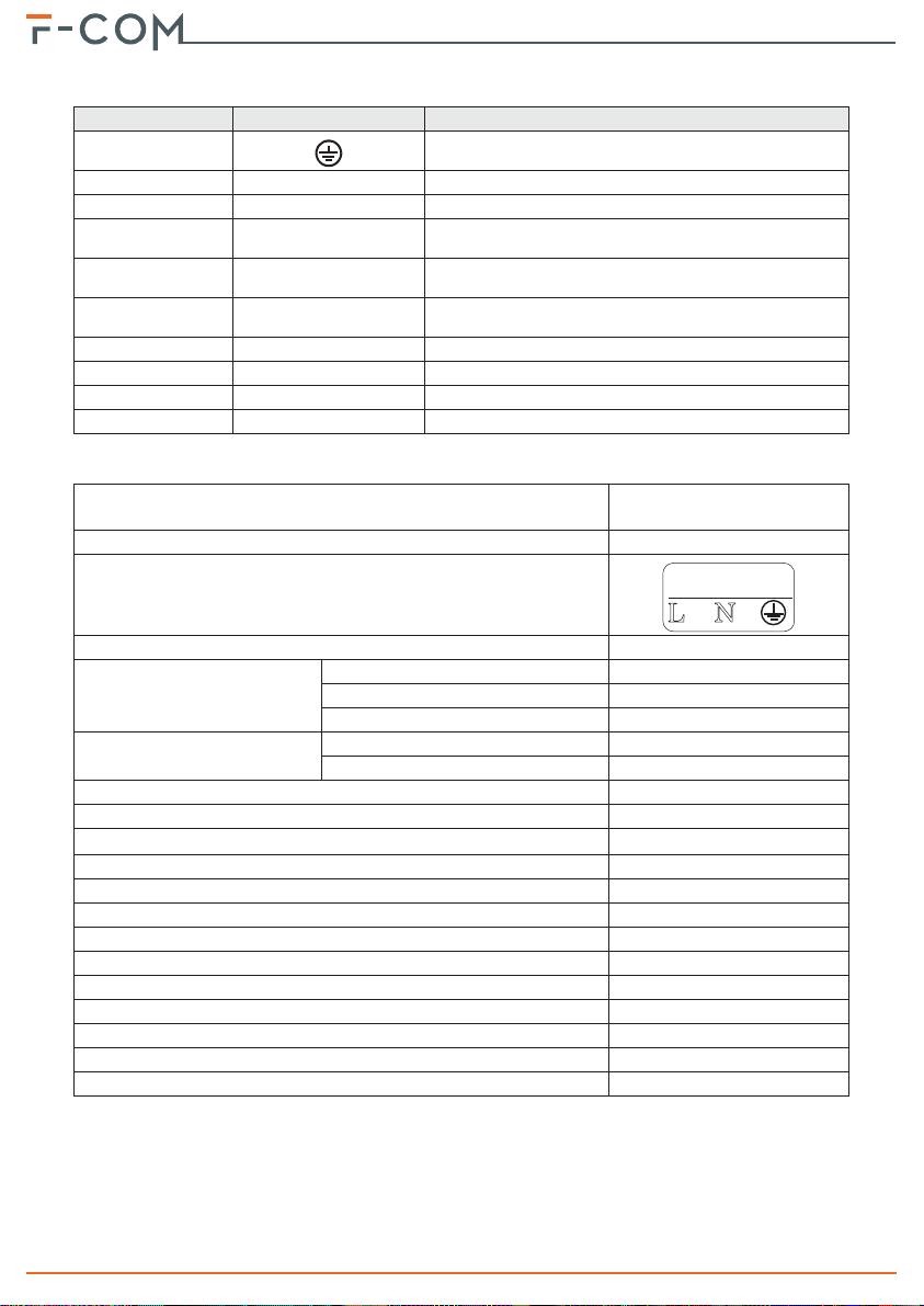
Table 3: Technical specifications
Supply voltage
230V~ (-15% + +10%)
50/60Hz
Maximum absorption from the 230V line
0.5A
AC mains input terminals
Nominal output voltage
27.6V
Maximum current supplied by
the power-supply module
total
2.1A
for battery charging
0.6A
for external loads and main board
1.5A
Main board current absorption during standby
50mA
during alarm
150mA
Battery specifications
2 x 12V / 1.3Ah
Minimum flammability class of casing
UL94-V2
Maximum internal resistance of battery (R
i max
)
2.7Ohm
Output voltage
19 / 27.6V
Battery shutdown tension
19V
Internal fuse of power supply module
T 3.15A 250V
Maximum output current ripple
1%
Operating temperature
from -5°C to 40°C
Insulation class
I
Enclosure protection class (EN 60529)
IP30
Classification in accordance with EN 54-21
Type 2
Dimensions (H x W x D)
260 x 200 x 55mm
Weight (without batteries)
1500g
N
L
230V ~ 50/60 Hz
AC I
nput

Device description 9
Installation and User manual
2-3CE Mark
,1,0(OHFWURQLFVVUO
9LD'HL/DYRUDWRUL)UD]&HQWREXFKL
0RQWHSUDQGRQH$3,WDO\
&35
(1$$
(1
)&20
Alarm transmission and fault warning routing equipment with embedded
power supply equipment for use with fire detection and fire alarm systems
installed in buildings
(VVHQWLDOIHDWXUHV
3HUIRUPDQFH
3RZHUVXSSO\SHUIRUPDQFH 3$66
7UDQVPLVVLRQSHUIRUPDQFH 3$66
2SHUDWLQJUHOLDELOLW\ 3$66
'XUDELOLW\RI
RSHUDWLQJUHOLDELOLW\
7KHUPDOUHVLVWDQFH 3$66
9LEUDWLRQUHVLVWDQFH 3$66
+XPLGLW\UHVLVWDQFH 3$66
(OHFWULFDOVWDELOLW\ 3$66
$GGLWLRQDOLQIRUPDWLRQDFFRUGLQJWR(1
)RUWKHLQIRUPDWLRQUHTXLUHGE\SRLQWVHHGDWDFRQWDLQHGLQWKLV
PDQXDO
$GGLWLRQDOLQIRUPDWLRQDFFRUGLQJWR(1
)RUWKHLQIRUPDWLRQUHTXLUHGE\SRLQWVHHGDWDFRQWDLQHGLQWKLV
PDQXDO

10 Installation
Telephone communicator
Chapter 3
INSTALLATION
3-1Wall-mounting
The installation must be carried out in full compliance with local fire regulations,
with the laws and provisions in force, and in accordance with the relative
instructions and guidelines.
The communicator should be located in a place that is:
•Dry
• Away from electromagnetic interference (electrical equipment, heating units,
air-conditioning units, radio transmitters, etc.) and metal objects.
ATTENTION!
Check that the GSM network signal of the selected provider is adequate.
1. Remove the securing screws and frontplate (table 1, P).
2. Using the back of the enclosure (table 1, Q), mark the anchor screw loca-
tions on the wall. Be sure not to drill in the vicinity of electrical wiring or
plumbing/gas pipes, etc.
3. Insert the screw anchors (recommended size 6mm).
4. Pull the connection wires through the wire entry (table 1, O).
5. Using the respective screws, attach the box to the wall.
6. Complete the connections with the terminals.
7. Replace the frontplate.
3-2Connecting the switching
power supply
The F-COM must be powered via the 230V~ mains power supply, with necessary
use of the two backup batteries.
3-2-1Mains power 230V~
For the power supply from the network, it is necessary to provide a separate line
deriving from the electrical distribution panel. The line must be protected by a
safety-standards compliant circuit breaker (trip switch).
The Grounding system of the site must be made in accordance with the current
regulations in force.
ATTENTION!
Use extreme caution when connecting to the primary power source. Danger of
electric shock.

Installation 11
Installation and User manual
1. Connect the mains power supply to the terminals on the power-supply
module ([A],table 1, K).
For a safety standards compliant system, the Line must be connected to terminal
“L” and the Neutral conductor to terminal “N”.
The power supply must come directly from an electrical distribution panel via a
reserved line. This line must be protected by a suitable sectioning device as
required by the local standards and laws in force.
Note
The electrical system of the building must have a magneto-thermal switch as an
additional protection against overcurrents and short circuits.
The end of a stranded wire must not be consolidated with soft soldering in points
where the wire is subjected to contact pressure.
2. Crimp the earth line wire to the eyelet terminal [B].
3. Secure the wire with the eyelet to the control panel using the ground con-
nection screw [C].
4. Ensure that the terminal “ ” of the power supply module [D]], the main
board [E] and the frontplate [F] are connected to Ground.
ATTENTION!
The earthing system must comply with current regulations regarding electrical
safety in the systems.
A protective earth connection ensures that all exposed conductive surfaces are at
the same electrical potential as the earth surface, in order to avoid the risk of
electrical shock when a person touches a device in which an insulation fault has
occurred. In the event of an insulation fault, a protective earth connection will
generate a high fault current which in turn will trigger an overcurrent protection
device (fuse) and disconnect the power supply.
5. Ensure that low-current safety or signal lines DO NOT come into contact
with points with potentially dangerous currents.
Using a plastic cable tie, bunch the wires together and secure them to one
of the wire hooks on the backplate of the enclosure [G].
The connection wires (to the mains supply and also any other wires inside the
cabinet) must be secured to the cable hooks on the backplate by means of plastic
cable ties. Use cable with double isolation for the connection to the electrical
mains.
A2
A2
A2
A2
A2
A2
A2
A2
A2
A2
A2
A2
A2A2
A2A2
E
+
-+
-
A
B
G
C
D
F
I
H
J
K

12 Installation
Telephone communicator
EN54To satisfy EN 54 standard requirements, when the communicator is not used with
an INIM control panel, it is necessary to insert the E-FAULT jumper of the power
supply.
3-2-2Connecting the batteries
The metal enclosure of the communicator is capable of housing two 12V 1.3Ah
lead batteries. The two batteries must be connected in series, in such a way as to
supply 24V.
1. Place the batteries into the battery compartment inside the enclosure (table
1, R).
2. Using the battery wire ([H]), connect the batteries together.
3. Connect the wire coming from the power supply ([I] table 1, M) to the bat-
tery terminals ([D]).
ATTENTION!
Ensure that the polarity is correct.
Red - positive
Black - negative
The connection of the batteries before the mains voltage is present will not
activate the system. Once the mains voltage is supplied, the power-supply module
will connect the batteries automatically and initialize the circuits which manage
them.
4. Position the thermal probe ([K], table 1, N). The thermal probe must be
positioned on the side of the battery and held in place by a strip of tape.
The lead batteries provide the secondary power source that will power the F-COM
and the devices connected to its outputs when the primary power source is not
present.
3-3Mounting the Antenna
1. Remove the antenna from the bag.
2. From above the enclosure, insert the antenna cable into its appropriate
placement (table 1, O).
3. Fit the antenna in the placement adapted for network reception using the
magnetic base or by attaching it to the wall by means of the two anchor
screws.
4. Using the ancillary wire, connect the antenna wire to appropriate connector
on the main board (table 1, F).
3-4Telephone connections
Connect the PSTN line (Public Switched Telephone Network) to the “L.E.”
terminals. (2 and 3, tabella 2 "Terminal board").
Note
The F-COM is protected against damage caused by lightening strikes.
Connect any telephone apparatus to the “L.I.” terminals. (4 and 5).
43215
L.E. L.I.
Installation 13
Installation and User manual
3-5Connecting to a PC
It is necessary to connect to a PC equipped with the F-COM-STUDIO software for
the programming, layout and monitoring of the system the F-COM is connected to.
The connection with the PC can be achieved through a USB cable inserted into the
appropriate connector on the main board (table 1, D).
Once the F-COM is connected, the driver for the installation of the USB device
recognized by the PC is available in the F-COM-STUDIO software installation
folder, specifically in the following folder (in the case of a default installation):
C:\Program Files\F-COM-STUDIO\drivers\
3-6Connecting the terminals EN54For the connection of the input/output terminals use:
Use shielded cable with the necessary number of conductors
Proper section (minimum 0.5mm², maximum 2.5 mm²)
Compliant with local standards and laws in force
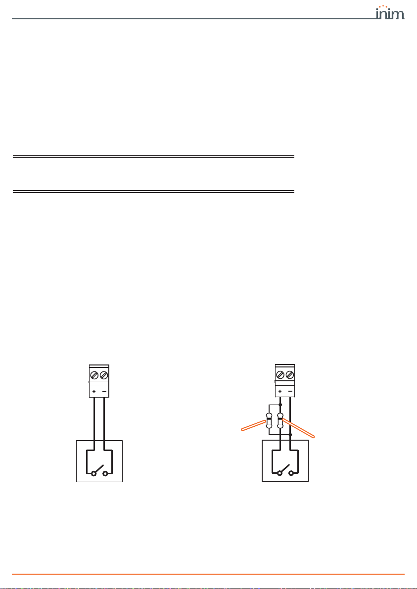
3-6-1ALARM CALL and FAULT CALL
connection
The “ALARM CALL” and “FAULT CALL” inputs are to be used for the start
communication signals relating to fire alarms and control panel faults.
These inputs can be supervised by connecting the appropriate balancing
resistance, and are compatible with the communicator output on Inim fire
detection panels.
The illustrated resistance values (3900 and 100Ohm) are those required when the
default input threshold values are used.
Since thresholds are programmable via the software, the installer can choose the
balancing resistance values.
When supervision is enabled, the occurrence of open and short-circuit conditions
will generate an “Interconnection fault”.
Following is the connection of the communicator with a SmartLine fire-detection
control panel manufactured by Inim Electronics, for alarm and fault
communications:
INPUT
3900Ohm
orange,
white, red 100Ohm
brown,
black, brown
ALARM/FAULT CALL
supervised
INPUT
ALARM/FAULT CALL
non-supervised

14 Installation
Telephone communicator
For SmartLine control panels it is necessary to enable the “Output to fault warning
routing equipment” option using SmartLeague software, above version 3.5.1.6.
PROGRAMMING
OPTIONS
•Polarity:
- Normally Open (default)
-NormallyClosed
•Supervision:
- Enable (default)
-Disabled
• Programmable thresholds
EN54The “ALARM CALL” terminal is an E function input for the signalling of alarms.
The “FAULT CALL” terminal is a J function input for the signalling of faults.
If you desire to maintain an EN54-21 standard compliant system, DO NOT disable
terminal supervision.
The voltage applied to the “ALARM CALL” and “FAULT CALL” terminals must be
between 0 to 3.3V=.
3-6-2Connecting ALARM ACK, FAULT
and OUT1 terminals
The three outputs, “ALARM ACK”, “FAULT” and “OUT1” are open-collector outputs
capable of driving maximum 150mA / 30V=.
The following wiring diagram illustrates connections for the activation of a load
when an output closes to ground.
FAULT
CALL RELAY
NONC
C
ZONE 4
I/O
AUX R
1500Ohm
brown,
green, red
100Ohm
brown, black,
brown
SmartLine
F-COM
ALARM
CALL DIALER
SmartLine
F-COM
3900Ohm
orange,
white, red
OUTPUT
Load
External
power
supply 30V=
max

Installation 15
Installation and User manual
The outputs can be supervised.
The “Interconnection fault” is activated in the event of:
• open-collector output open, if the load to positive is not detected or when a
short-circuit to ground is detected
• open-collector output closed, in the event of an internal fault
PROGRAMMING
OPTIONS
•Polarity
- Normally Open (default for “ALARM ACK” and “OUT1”)
- Normally Closed (default for “FAULT”)
•Supervision
- Enabled
- Disabled (default)
• Monostable/Bistable
• Monostable duration
“ALARM ACK” and “FAULT” cannot be programmed as monostable; “OUT1” is
bistable at default.
3-6-3Connecting IOx terminals as
inputs
The three terminals, “IO1”, “IO2” and “IO3” are configured as inputs at default.
These terminals can be supervised by connecting the appropriate balancing
resistances. The illustrated resistance values (3900 and 100Ohm) are those
required when the default input threshold values are used.
Since thresholds are programmable via the software, the installer can choose the
balancing resistance values.
Table 4: Output functions
terminal activation deactivation
ALARM ACK
Activates each time an alarm communication is
confirmed from remote:
- in the case of a voice call when the
“
*
” key is pressed on the telephone in
use
- in the case of a digital communication,
on reception of the “ACK” signal
If configured as bistable, this output is restored
when the communicator is rearmed.
FAULT
Activates in the event of one or more faults:
- interconnection fault
- battery fault
-nobattery
- power supply fault
- mains failure
- ground fault
- programming fault
-PSTNfault
- SIM fault
- insufficient SIM credit
- mobile network fault (GSM)
- mobile network data fault
If configured as bistable, the output will restore
when all the faults restore.
OUT1
Activates in response to the events configured for
this output (refer to Appendix A).
At default it activates when the “Interconnection
fault” occurs.
It restores when the event configured for this
output restores (refer to Appendix A).
At default it restores when the “Interconnection
fault” restores.

16 Installation
Telephone communicator
When supervision is enabled, the occurrence of open and short-circuit conditions
will generate an “Interconnection fault”.
CONTACT
REFERENCE
Each "IOx" terminal has an internal resistor, a "pull-up" resistor, which allows to
change the contact reference (to ground or positive) according to the
programming.
Therefore, there are 4 ways of connecting a contact to an IOx input:
• normally-closed contact referred to ground (negative removed)
• normally-open contact referred to ground (negative applied)
• normally-closed contact referred to positive (positive removed)
• normally-open contact referred to positive (positive applied)
It is possible to associate one of the functions in the following table to each input:
INPUT
3K9Ohm
orange,
white, red 100Ohm
brown,
black, brown
Terminal IOx
supervised
INPUT
Terminal IOx
non supervised
Table 5: IOx functioning as input
function input activated note
Stop alarm communications If the input is activated, the specified
communication types will be cancelled
from the call queue and any ongoing calls
will be terminated.
One or more communication types can
be selected.
Default for terminal “IO2”.
Stop fault communications
Stop other types of communications
(generic or supervision)
Disable alarm communications If the input is activated, the specified
communication types will be disabled.
One or more communication types can
be selected.
Default for terminal “IO3”.
Disable fault communications
Disable other communication types
(generic or monitoring)
Force call to cellular channel If the input is activated, it will force the
communicator to use the mobile network
for voice and Contact ID calls.
Forcing will have no effect if at the
same moment another input
configured as “Force calls to PSTN” is
active.
Force calls to PSTN If the input is activated, it will force the
communicator to use the PSTN line for
voice and Contact ID calls.
Forcing will have no effect if at the
same moment another input
configured as “Force calls to cellular
channel” is active.
Rearm
Activation of the input:
- terminates ongoing communications
and cancels any communications in
the call queue
- switches off the “ACK” LED and
yellow blinking on the “Power” LED
(that indicates “System restart”)
- terminates audible alarm and fault
signalling (on buzzer), the signalling
will restart when a new alarm or
fault signal event occurs
- deactivates the “ALARM ACK” output
- deactivates the programmable
outputs (“OUT1”, “IOx”)
The monostable outputs will
deactivate unconditionally.
For Bistable outputs, the non-
restorable events will be considered
“zeroed” (refer to Appendix A),
however, in order to allow the output
to be deactivated, it is necessary for
all the associated events to restore.
Default for terminal “IO1”.

Installation 17
Installation and User manual
If none of the functions in the table are associated with an input, the activated
actions will be those specified by events/actions programming (refer to Appendix
A).
PROGRAMMING
OPTIONS
•Polarity:
- Normally Open contact (default)
-NormallyClosedcontact
•Supervision:
- Enabled
- Disabled (default)
• Contact reference
- Ground (default)
- Positive
• Programmable thresholds
When the “IOx” terminals are programmed as inputs, the voltage applied must be
between 0 and 3.3V=.
3-6-4Connecting IOx as outputs
If set as an output, the “IOx” terminal operates as an open-collector output,
capable of driving maximum 150mA / 30V=.
These terminals can be programmed to activate in the presence of events as per
event/action programming (refer to Appendix A)
The outputs can be supervised.
The “Interconnection fault” is activated in the event of:
• open collector output open, if the load to positive is not detected or if a short
circuit to ground is detected)
• open-collector output closed, in the event of an internal fault
PROGRAMMING
OPTIONS
•Polarity
-NormallyOpen
-NormallyClosed
•Supervision
- Enabled
-Disabled
• Monostable/Bistable
• Monostable duration

18 First startup
Telephone communicator
Chapter 4
FIRST STARTUP
To perform a correct first startup operation, work carefully through the following
steps.
ATTENTION!
During the completion of wiring, do not power the F-COM or any connected
devices, neither via mains (230V a.c.) nor battery.
1. Attach the F-COM to the wall.
2. Connect the antenna.
3. Connect the input and output terminals to the fire detection system.
4. Connect the telephone line (if required).
5. Insert the SIM card (if required).
6. Connect the primary power source (230V~).
7. Connect the backup batteries.
Start the initializing phase.
8. Follow the guided programming wizard on the screen.
4-1Guided programming
(initial setup wizard)
On first startup of the communicator or restoring of factory data, the display
provides the user with a fast programming guide.
By following this guided procedure and configuring at least one telephone contact,
thanks to the actions programmed at default (refer to Appendix A), the F-COM will
be able to:
• make voice calls for the activation of ALARM CALL and FAULT CALL terminals;
• send SMS texts and digital communications (Contact ID, SIA-IP, IP2RX) for
the activation of ALARM CALL and FAULT CALL terminals as well as for the
activation/reset of the important internal events of the communicator.
The steps of the guided procedure are:
1. Language selection: Italian or English (default)
2. Setting the date and time
3. Configuration of phone contact n.1
4. Configuration of phone contact n.2
The configuration of the contacts initially requires the type and, based on this, the
parameter settings:
Table 6: Fast configuration of contacts
Contact type Required parameters
Voice Telephone number
Preferential channel (PSTN or mobile)
Supervision period
SMS Telephone number

First startup 19
Installation and User manual
EN54In order to guarantee compliance with the EN 54-21 standard, supervision must
be enabled and the maximum period must be 24 hours.
5. Configuration of access to the mobile data network.
The last step is implemented only when the type of one of the set contacts is SIA-
IP or IP2RX. APN, username and password will be requested.
After entering this data the communication channel of the mobile data network
will be enabled.
Contact ID
Telephone number
Preferential channel (PSTN or mobile)
Account code
Supervision period
SIA-IP
IP address
Port
Account code
Supervision period
IP2RX
IP address
Port
Account code
Supervision period
Table 6: Fast configuration of contacts

20 Using the communicator
Telephone communicator
Chapter 5
USING THE
COMMUNICATOR
5-1Users
The F-COM communicator manages different access levels to the device, distinct
from the system usability limitations.
Each user must have an access PIN the first digit of which characterizes the
typology and cannot be changed:
5-2User interface
Table 7: Access levels
description permissions access mode
Standard user
Access to the viewing of:
- diagnostic information
- fault details
-eventslog
User PIN
Default 000000
Advanced user
The same permissions as the standard user, plus the possibility to
change some programming options relating to the contacts:
- telephone numbers
- communication protocol
- IP address, port, account code
Advanced user PIN
Default 111111
Installer
The same permissions as the standard user, plus the possibility to
carry out the battery test.
By means of the programming software, change all the
programming options.
Installer PIN
Default 222222
F-COM inim.biz
CARRIER
20/05/2019 18:23:00
ENTER PIN: [ ]
Table 8: Signalling LEDs
Icon description activation signal
Telephone
line
Indicates that the communicator is
engaged in an ongoing call on the
PSTN channel or the presence of a
PSTN fault.
- Flashing green, indicates an ongoing
communication on the PSTN, different from an
alarm communication.
- Flashing red, indicates an ongoing alarm
communication on the PSTN.
- Solid yellow, indicates a fault on the PSTN line
(line down on “L.E. terminals”)
Table of contents
Other INIM Electronics Cell Phone manuals


