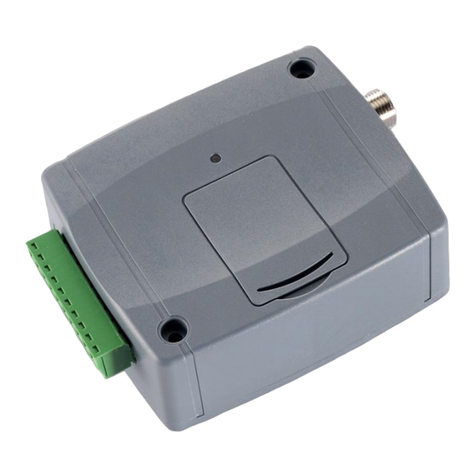
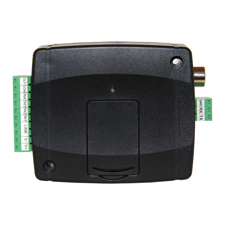
tell DUALCOM SIA IP User guide

DUALCOM SIA IP
INSTALLATION AND APPLICATION MANUAL
for module version V1.20.1837 and up
Document version: 1.61 12.08.2013

2
Table of contents
1Application ..............................................................................................................3
2Functions ................................................................................................................3
3Module overview.....................................................................................................3
4Operating logic........................................................................................................4
4.1 Estimated data traffic.......................................................................................4
5Settings...................................................................................................................5
5.1 Configuring through USB connection..............................................................5
5.1.1 Establishing the connection .................................................................6
5.1.2 Function buttons of the programming software ...................................6
5.1.3 Phone numbers....................................................................................6
5.1.4 SIM ”A” / SIM ”B” GPRS settings.........................................................7
5.1.5 Input settings........................................................................................8
5.1.6 Relay outputs .....................................................................................10
5.2 Configuring by SMS commands....................................................................11
5.3 Module status monitoring ..............................................................................13
5.3.1 Module status.....................................................................................13
5.3.2 LED signals (GPRS A and GPRS B) .................................................14
6Connection diagram..............................................................................................15
7Installation guide...................................................................................................15
7.1 Mounting........................................................................................................15
7.2 Putting into operation ....................................................................................15
8Technical details ...................................................................................................16
8.1 Technical specification ..................................................................................16
8.2 Contents of the package ...............................................................................16

3
1 Application
Communicator for fire alarm control panels, that converts the contact input events to
SIA IP format and sends to the alarm monitoring receiver through IP channel on mobile
GPRS network. It can be used for any control panel which has contact outputs or the
contact outputs can be obtained with relays. Using this module, the input events are sent
to the monitoring station’s IP receiver over the GPRS network, using SIA IP protocol
based on ANSI/SIA DC-09-2007 standard. No need for a central server, only an IP
receiver with internet connection is necessary. The module works with the following
receiver types: TELLMon,AMR-08 and ENIGMA II.
2 Functions
Parallel usage of two independent GSM modules
Reporting up to 4 IP addresses, which means 2 primary IP addresses per network
6 NO/NC/EOL contact inputs
6 alarm activated NO relay outputs
Programmable by PC software and by SMS
Test report with configurable sending frequency for automatic checking of the
transmission channel
The programming software and manual are available on the internal memory of the
device which acts as a USB drive
3 Module overview

4
4 Operating logic
The events generated on the contact inputs are sent towards the preset receiver IP
addresses through both independent GPRS channels simultaneously. The requirement
for the simultaneous operation is a receiver pair operating on 2 different networks on the
remote monitoring station side.
The logical scheme in the figure below illustrates the primary reporting method.
Explanation of IP address markings:
Priority Monitoring station
numbering GPRS network provider marking
Primary 1
A= e.g. Vodafone B= e.g. Telenor
Primary 2
A= e.g. Vodafone B= e.g. Telenor
After an event occurs, the module establishes IP connection with the configured primary
IP addresses through both networks (A and B) at the same time. Reporting is done
through the different networks and to the different remote monitoring stations in parallel.
Due to the parallel operation, ideally each receiver receives the event roughly at the
same time (this is an average of 5 seconds). If on the module side one of the networks
fails or delay occurs, the other network’s transfer rate and availability is still provided.
The system provides possibility to build up 2 primary remote monitoring stations. The two
primary monitoring stations seen in the figure above can be completely equivalent or
functionally divided (e.g. alarm and technical). If reporting to only one remote monitoring
station is satisfactory, then it is enough to configure only Primary 1A and Primary 1B IP
addresses.
4.1 Estimated data traffic
In case of using TCP protocol, with test report sending by 60 seconds, the data traffic is
expected to be about 25MB/month for each configured IP address. In case of using UDP
protocol this is expected to be about 9MB/month.

5
5 Settings
The module settings can be configured by PC software through USB, and the main
parameters can also be configured remotely by SMS commands.
5.1 Configuring through USB connection
The programming software is available on the module’s USB drive. After connecting the
module to USB, it will be recognized as a USB drive and also creates a USB HID device.
Since it is a HID device, the USB connection requires no special drivers.
The programming software runs on the following operating systems:
Windows XP SP2 (32/64 bit)
Windows 7 (32/64 bit)
The language of the program interface can be selected using the language icons found
in the lower right corner of the program window.
Programming:
Copy the programming software from the module to a suitable place on the PC.
The software is available in the following folder:
”Drive letter”:\Software\Remoter\Remoter.exe
Start the Remoter.exe programming software
Power up the module from external power supply. (If the module is powered only
from USB, it establishes the connection with the software after 25 seconds and
then it accepts programming for 2 minutes only!)
Connect the module to USB
As soon as the program connects to the module, it requests the module password,
then a green tick icon appears next to the USB icon in the upper right corner of the
main window:
Thereafter the “Read” and “Write” function buttons become available on the
“Settings” page as well as status information on the “Status” page of the software.
Configure the settings, then write them to the module using the “Write” button.

6
5.1.1 Establishing the connection
When connecting, the module
requests the security password. The
default password is: 1111.
To log in, select “Login” option, enter
the current password, then press “OK”
or Enter key.
To change the password, select
“Change password” option, enter the
current password, the new password
twice, then press “OK” or Enter key.
5.1.2 Function buttons of the programming software
Read: read settings from the connected module
Write: write settings to the connected module
Open: load settings from file
Save: save settings to file
5.1.3 Phone numbers
Superuser: it is possible to configure the module by sending commands in SMS to the
module’s phone number. The module accepts SMS commands only from the Superuser
phone number. You can enter the superuser phone number here, or can register it by
SMS. You can find the list of the available SMS commands in chapter “Configuring by
SMS commands”.

7
5.1.4 SIM ”A” / SIM ”B” GPRS settings
SIM ”A”: the network belonging to SIM card “A” (placed on the right side of the panel)
SIM ”B”: the network belonging to SIM card “B” (placed on the left side of the panel)
APN name: internet access point name (belongs to the SIM card, is provided by the
mobile service provider)
User and password: user and password for the APN (necessary only if requested by the
mobile service provider)
PIN: the module supports PIN code usage on the SIM cards inserted in sockets SIM “A”
and SIM “B”. If you wish to use this function, enter the PIN code here and enable PIN
code request on the SIM card. The module will provide the PIN code upon each power
up and upon daily restarts when the PIN is requested by the SIM card.
Attention! The SIM card will become blocked if you enter the wrong PIN code!
Thereafter it can be unlocked by inserting in a cell phone and entering the PUK code.
Receiver settings:
Attention! For system safety it is mandatory to configure the IP addresses in pairs,
which means if IP Ais set, Bmust also be set and vice versa!
Primary 1A, 2A: the primary receivers belonging to SIM ”A” network
Primary 1B, 2B: the primary receivers belonging to SIM ”B” network
Comment: in this textbox you can add a name to the given receiver. The module does
not use the name entered here, but it is saved with the settings as informative data for an
easier system overview.
IP address: the IP address of the given receiver
Port: the port number that belongs to the given IP address
Account ID.: the user account ID which the module uses when sending events towards
the receiver found on the given IP address
Test freq: the test report frequency in seconds (60…3600s). The module sends GPRS
test report using the sending frequency set here to verify the connection with the receiver
on the given IP address.
Attention! The lower the value set, the higher the data traffic will be!
Protocol: select the appropriate communication protocol from the drop-down list for the
receiver available on the given IP address.
Available protocols: TELLMon_TCP, TELLMon_UDP, AMR-08 and ENIGMA II.
The UDP protocol allows for less data traffic.

8
5.1.5 Input settings
IN1…IN6: the settings of the 6 contact inputs. The normally open or normally closed
contact is considered between the given IN input and the COM common terminal (see
connection diagram).
Input tamper event: the sabotage (tamper) event applies globally to all EOL inputs.
The number of the affected input (001…006) is inserted automatically the in the “zone”
section of the tamper Contact ID code. The module does not send tamper event for
non-EOL inputs.
Battery trouble: the module monitors its supply voltage level and sends report if the
voltage exceeds the configured “low battery voltage/restore” voltage levels for at least
30 seconds.
Low battery voltage threshold: the module is able to monitor the supply voltage.
This function is useful when the module is powered from uninterrupted power supply,
provided with a backup battery (recommended). You can set a threshold between
10…30V, at which the module generates “Battery trouble” event. The event is
generated if the supply voltage is continuously below the configured level for at least
30 seconds.
Voltage restore threshold: you can set a threshold between 10…30V, at which the
module generates “Battery trouble restore” event. The event is generated if the supply
voltage is continuously above the set level for at least 30 seconds after a “battery trouble”
event.
Type:
NO – normally open (the input is normally open, and it generates alarm event
when shorted)
NC – normally closed (the input is normally closed, and it generates alarm event
when opened)

9
EOL: if enabled, then tamper protection function is automatically activated for the given
input. In this case the given input must be provided with an 1kΩend-of-line resistor at the
end of the loop, directly at the controlling contact (see connection diagram).
Sensitivity: the input sensitivity can be set in milliseconds between 10 and 10000.
Shorter state changes on the given input are ignored by the module upon activation and
restore as well.
Attention! After changing the sensitivity settings, the module considers the first
activation on the given input still with the old setting! The new setting is validated
only after the first activation or after module restart.
CID code: 3-digit event code, consisting of 0..9,A,B,C,D,E,F characters for reporting to
monitoring station. (e.g. 110 = fire alarm). The restoration event is sent automatically
upon restore (for inputs, according to the input sensitivity settings). For inputs and tamper
event the module sends the zone number (001…006) automatically, according to the
number of the activated input (IN1…IN6).
Receiver pairs: by checking the 1AB and 2AB checkboxes, you can enable for each
event which receiver pairs to be sent to through the two independent GPRS networks.
By this, it is possible to separate e.g. the alarm events and technical events (send alarm
events only to the alarm monitoring station, and technical events only to the technical
monitoring station) – see chapter “Operating logic”.
1AB enabled: reporting is performed to receivers 1A and 1B:
Primary 1A Primary 1B
2AB enabled: reporting is performed to receivers 2A and 2B:
Primary 2A Primary 2B
Name: in this textbox you can add a name to the given input/event. The module does not
use the name entered here, but it is saved with the settings as informative data for an
easier system overview.

10
5.1.6 Relay outputs
The module has 6 relay outputs (Output 1…6) for any of which any of the following
functions can be configured:
follows input 1 status: the output is activated when input 1 is activated and
remains activated as long as input 1 is active.
follows input 2 status: the output is activated when input 2 is activated and
remains activated as long as input 2 is active.
follows input 3 status: the output is activated when input 3 is activated and
remains activated as long as input 3 is active.
follows input 4 status: the output is activated when input 4 is activated and
remains activated as long as input 4 is active.
follows input 5 status: the output is activated when input 5 is activated and
remains activated as long as input 5 is active.
follows input 6 status: the output is activated when input 6 is activated and
remains activated as long as input 6 is active.
On, if any input is active: the output is activated when any of the 6 inputs is
activated and remains activated as long as any input is active.
Indicates battery trouble: the output is activated upon battery trouble and
remains activated as long as the battery trouble lasts. The output activation and
deactivation coincides with the generation of battery trouble and battery restore
events.
Indicates communication trouble: the output is activated if the module is unable
to establish the connection with the receivers through any of the configured
channels, and remains activated until the connection is established through at
least one of the configured channels.
Attention! The continuity of the activated state of the outputs may temporarily be
interrupted! The activated output is deactivated for 1-2 seconds if the module restarts,
then after restart the module restores the active state. An exception to this is the
communication trouble indication, where the active state is restored only if
communication trouble occurs again after restart. Module restart may occur if this is
necessary in order to restore a connection or for the further proper operation, as well as
upon the daily automatic restart.

11
5.2 Configuring by SMS commands
The table below contains the commands to be sent in SMS to the module’s phone
number in order to configure the module. The module accepts SMS commands only from
the SUPERUSER phone number.
It is possible to send more commands in one SMS, but the message length should not
exceed 40 characters, otherwise the module responds with an error message. Each
command must end with #character.
There is possibility for settings query at some of the commands, these are marked
with ? character in the first table column. The module will send the requested settings in
SMS. For settings query send the command in SMS using question mark after the
command (e.g. IP1A?#).
Commands should always be typed using capital letters. The first step is to register the
SUPERUSER phone number using the programming software or by sending the
SUPERUSER# command in SMS to any of the module’s phone numbers, from the
number wished to be registered.
Command Value
Superuser registration SUPERUSER (registers the sender’s phone number) #
? Modifying / deleting the Superuser SU = phone number #
? APN assigned to SIM ”A” APNA =APN name (e.g. internet)#
? APN user name assigned to SIM ”A” APNUA =user name #
? APN password assigned to SIM ”A” APNPA =password #
? SIM ”A” PIN code PINA =PIN code #
? APN assigned to SIM ”B” APNB = APN name (e.g. internet)#
? APN user name assigned to SIM ”B” APNUB = user name #
? APN password assigned to SIM ”B” APNPB = password #
? SIM ”B” PIN code PINB = PIN code #
? Primary 1A comment IPC1A =comment #
? Primary 1A IP address IP1A =IP address (e.g. 111.222.33.44)#
? Primary 1A port number PORT1A =port (e.g. 3535)#
? Primary 1A user account ID UID1A =user account ID (e.g. 1234)#
? Primary 1A test sending frequency FR1A =test frequency (in seconds) (e.g. 60)#
? Primary 1A protocol PROT1A =
TELLMon_TCP
TELLMon_UDP
AMR-08
ENIGMA_II
#
? Primary 2A comment IPC2A = comment #
? Primary 2A IP address IP2A = IP address (e.g. 111.222.33.44)#
? Primary 2A port number PORT2A = port (e.g. 3535)#
? Primary 2A user account ID UID2A = user account ID (e.g. 1234)#
? Primary 2A test sending frequency FR2A = test frequency (in seconds) (e.g. 60)#
? Primary 2A protocol PROT2A =
TELLMon_TCP
TELLMon_UDP
AMR-08
ENIGMA_II
#

12
? Primary 1B comment IPC1B =comment #
? Primary 1B IP address IP1B =IP address (e.g. 111.222.33.44)#
? Primary 1B port number PORT1B =port (e.g. 3535)#
? Primary 1B user account ID UID1B =user account ID (e.g. 1234)#
? Primary 1B test sending frequency FR1B =test frequency (in seconds) (e.g. 60)#
? Primary 1B protocol PROT1B =
TELLMon_TCP
TELLMon_UDP
AMR-08
ENIGMA_II
#
? Primary 2B comment IPC2B = comment #
? Primary 2B IP address IP2B = IP address (e.g. 111.222.33.44)#
? Primary 2B port number PORT2B = port (e.g. 3535)#
? Primary 2B user account ID UID2B = user account ID (e.g. 1234)#
? Primary 2B test sending frequency FR2B = test frequency (in seconds) (e.g. 60)#
? Primary 2B protocol PROT2B =
TELLMon_TCP
TELLMon_UDP
AMR-08
ENIGMA_II
#
? Low battery voltage threshold BATL =e.g. 11800 (9000…30000 mV) #
? Voltage restore threshold BATH =e.g. 12500 (9000…30000 mV) #
Restart module after 30sec. RESET = 1 #
The module sends response message about the modifications, e.g. IP1A OK, except for
the superuser registration.
Examples:
Registering the Superuser phone number:
SUPERUSER#
The module executes the registration, but does not send response message for this
command!
Erasing the Superuser phone number:
SU=#
Setting the Primary 1A IP address (e.g. 111.222.33.44), port number (e.g. 3545), user
account ID (e.g. 1234), test frequency (e.g. 60s) and the protocol (e.g. TELLMon_UDP),
then restarting the module:
IP1A=111.222.33.44#PORT1A=3545#UID1A=1234#FR1A=60#
PROT1A=TELLMon_UDP#RESET=1#
Setting the low battery and restore voltage thresholds (e.g. 11,8V and 12,5V):
BATL=11800#BATH=12500#
Querying the Primary 1B IP address, port number and user account ID:
IP1B?#PORT1B?#UID1B?#
To erase a setting value, do not write a new value in the command, leave the value part
blank. E.g. to erase the Primary 1B IP address:
IP1B=#

13
5.3 Module status monitoring
5.3.1 Module status
In the Status window you can check the status of the connected module:
Version information:
- Type: the type of the module
- Hardware version: the module’s hardware version
- Firmware version: the module’s firmware version
System timer:
- Date/time: the date and time setting of the module’s internal clock
- Uptime: the time elapsed from last module restart (seconds)
Inputs (IN1…IN6): the actual state of the contact inputs :
- Idle: the input is in idle state
- Alarm: the input is in alarm
- Tamper (open): sabotage (for EOL inputs) – loop open

14
GSM status (SIM1 / SIM2):
- GSM signal: the actual GSM signal
- GSM network: the name of the GSM network in use
- Uptime: the time elapsed from connecting to the GSM network
GPRS network:
- Module IP: the actual IP address of the given SIM card
- Uptime: the time elapsed from connecting to the GPRS network
Receiver status (1A, 2A - 1B, 2B): the connection status of the receivers:
(3A, 4A - 3B, 4B: for future use)
- Online: IP connection ok, ready
- Online (ACK error): IP connection ok, but no acknowledgement signal is received
(alarm monitoring software serial connection error)
- Offline (No response): no response is received from the configured IP address
(no receiver on the configured IP address)
- Offline: no IP connection
- Not configured: IP address is not set for the given receiver
Event list: the list of the latest events.
5.3.2 LED signals (GPRS A and GPRS B)
Slow flashing green Connected to GPRS network, idle state
Fast flashing green Reporting through IP in progress
Flashing red Start/restart in progress
Red is lit permanently Error

15
6 Connection diagram
*The RX/TX port is not available in this version!
7 Installation guide
7.1 Mounting
Test the GSM signal with your mobile phone then after installation repeat the test
with the module! It may happen that the signal strength is not sufficient in the
desired mounting place. In this case the planned installation place can be changed
before mounting the device.
Do not mount the unit in places where it can be affected by strong electromagnetic
disturbances (e.g. in the vicinity of electric motors, etc.).
Do not mount the unit in wet places or places with high degree of humidity.
Connecting the GSM antenna: the GSM antennas can be fixed in the FME-M
connectors found on the panel. The antennas supplied with the module provide
good transmission under normal reception circumstances. In case of occasionally
occurring signal strength problems or/and wave interference (fading), use another
(directed) type of antenna or find a more suitable place for the module.
7.2 Putting into operation
Disable voicemail and notification in SMS about missed calls on the SIM cards
placed into the module.
If you enable PIN code request on the SIM cards, then enter the PIN codes in the
module settings as well.
Activate the mobile data traffic package for the SIM cards at the GSM service
provider.

16
Inserting the SIM cards:
Attention! Inserting or removing the SIM card when the module is powered up is
strictly prohibited! In this case both the SIM card and the module may suffer
breakdown that automatically implies loss of warranty!
Insert the SIM cards in the SIM A and SIM B sockets:
1. pull the metal security lock of the SIM slot upwards (towards the upper edge
of the panel) until it clicks
2. reach under the metal security lock with your fingernail and open the socket
3. slide the SIM card into the opened part with the contacts facing down, as
shown in the figure above
Close back the opened part together with the SIM card
Press down carefully and pull the metal security lock downwards (towards USB
connector) until it clicks
Check the SIM cards to be inserted properly.
Check the antennas to be fixed properly in the FME-M connectors.
The device can be powered up. Make sure the power is sufficient for the operation
of the module. The quiescent current of the module is 70mA, however it may
increase up to 400mA during communication and output control.
8 Technical details
8.1 Technical specification
Supply voltage: 9-30V DC
Nominal consumption: 70mA @ 12V DC, 40mA @ 24V DC
Maximum consumption: 400mA @ 12V DC, 200mA @ 24V DC
Operating temperature: -20ºC - +70ºC
Transmission frequency: GSM 900/1800 MHz
GSM phone type: Simcom SIM900
Dimensions: 116 x 100 x 25mm
Weight: 280g (packed: 300g)
8.2 Contents of the package
DUALCOM SIA IP module
2pcs GSM 900/1800MHz antenna
Plastic spacer support / snap fasteners
Installation and application manual
Warranty card
Table of contents
Other tell Cell Phone manuals
