INIM Electronics IPS24140 User manual

Il modulo alimentatore caricabatteria
IPS24140 è stato sviluppato secondo i
criteri di qualità, affidabilità e prestazioni
adottati dalla INIM Electronics. I compo-
nenti utilizzati garantiscono idonei requisiti
di funzionamento quando le condizioni am-
bientali esterne al modulo sono in accordo
con la categoria 3k5 della IEC 721-3-3.
Il modulo di alimentazione IPS24140
fornisce una tensione stabilizzata a 27,6V
ed una corrente massima di 4A . Le uscite
sono protette da sovraccarichi, corto circuiti
ed inversione accidentale delle polarità
dell’eventuale batteria ad esse collegata.
Installazione
Collegare i conduttori provenienti dalla rete
elettrica alla morsettiera
1
(vedi
Fig. 1
).
ATTENZIONE!
• E’ necessario collegare il conduttore
di terra.
• I conduttori provenienti dalla rete
elettrica devono essere fascettati e
fissati in prossimità del loro ingresso
al modulo alimentatore.
Per il fissaggio del IPS24140 all’interno di
contenitori od apparecchiature utilizzare i
due semifori di fissaggio 2.
Ruotando il trimmer
3
è possibile eseguire
dei piccoli aggiustamenti della tensione di
uscita; il modulo viene fornito già tarato.
The IPS24140 Switching power supply/
Battery charger has been designed and
made to the highest standards of quality
and performance. INIM Electronics guar-
antees proper functioning of the compo-
nents utilized in this product when the
environment external to the module com-
plies with Class 3k5, IEC 721-3-3.
The IPS24140 unit supplies a regulated
voltage of 27.6V and a maximum current
of 4A. Its power output is protected
against overload, short-circuit and acci-
dental inversion of the polarity of the con-
nected batteries.
Installation
Connect the mains wiring to the input ter-
minals 1(see Fig. 1).
ATTENTION!
• This device must be earthed.
• Using a plastic cable band, bunch the
mains wires and fasten them near to
the mains wire entry.
Using the mounting holes 2, secure the
IPS24140 inside its housing.
The power supply is calibrated at the fac-
tory, however, minor adjustments of the
output voltage can be made using the
trimmer 3.
IPS24140
Alimentatore/Caricabatteria switching da 27,6V dc 4A
27.6V dc 4A switching Power Supply/Battery Charger
Certificato EN60950-1
EN60950-1 certified
DCMIINIEIPS24140-R120-20101013

2
IPS24140
La spia luminosa 4segnala la presenza
della tensione di rete ed il corretto funzio-
namento dell’apparecchio.
La tensione di uscita può essere prelevata
o dai morsetti 5 (+V,-V), o dal connettore
6(+V, -V); sul connettore 6è inoltre
possibile prelevare un segnale di man-
canza rete elettrica (FAULT: 5V = Rete
Ok, 0V = No Rete) ed è disponibile un in-
gresso per la connessione di una sonda
termica alloggiata in centrale (RTH, utiliz-
zato SOLTANTO da centrali INIM, NON
UTILIZZARE).
Utilizzo con centrali rivelazione incendio
Nel caso di utilizzo del presente apparato
in abbinamento con centrali di rivelazione
incendio tutte le segnalazioni obbligatorie
di stato e di guasto devono essere previste
e rese disponibili in centrale.
La connessione delle batterie deve essere
realizzata mediante un opportuno disposi-
tivo di sezionamento che garantisca il
funzionamento dell’alimentatore anche in
caso di corto circuito delle batterie.
The LED 4 indicates the presence of the
mains voltage on the input terminals and
the proper working order of the device.
The output voltage can be taken from ter-
minals 5 (+V, -V), or from the connector
strip 6(+V, -V) which also provides a fault
output for mains fault signals (FAULT: 5V
= Mains OK; 0V = No Mains).
DO NOT USE the connector marked RTH ,
as it is suitable for use with INIM control
panels ONLY).
Use with fire control panels
If you use this device with fire control panels
all obligatory status and fault signalling
must be provided for, and made available.
An automatic isolating device must be used
for the battery connection; this will allow
the power supply unit to function properly in
the event of batteryshort-circuit.
1
Morsettiera ingresso rete Mains input terminals
2
Foro di fissaggio 3,25mm Mounting holes 3.25mm
3
Trimmer Trimmer
4
Spia luminosa LED indicator
5
Morsettiera uscita Output terminals
6
Connettore uscita Output connector
7
Connettore per sonda termica Thermal probe connector
8
Fusibile d’ingresso (F1) F 3,15A 250V Input protection fuse (F1) F 3.15A 250V
9
Fusibile d’uscita (F2) F 8A 250V Output protection fuse (F2) F 8A 250V
NL
230V ~ 50/60 Hz
AC I
nput
8
4
3
7
6
5
2
9
Fig.1
2
22
1
I
I
IPS24140
3
Sonda termica
L’alimentatore può essere dotato di una
sonda termica opzionale (ProbeTH dispo-
nibile a catalogo) in grado di adattare la
tensione di ricarica delle batterie alla loro
temperatura, per una ricarica più efficien-
te.
Per installare la sonda termica ProbeTH
procedere come di seguito:
1. Disconnettere le batterie in uscita.
2. Collegare la sonda al connettore 7.
3. Collegare un multimetro al connettore
di uscita 5.
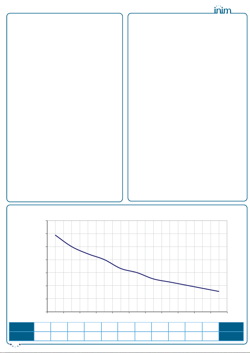
4. Valutare la temperatura della sonda
ed in base al grafico (Fig.2)ricavare
la tensione di ricarica per tale tempe-
ratura (p.e. con una temperatura di
20°C la tensione deve esser 27,16V).
5. Regolare il trimmer 3 fino ad ottenere
la tensione di uscita ricavata dal gra-
fico.
6. Collegare le batterie e posizionare la
sonda a contatto con esse assicuran-
dosi di ottenere una buona conducibi-
lità termica.
ATTENZIONE!
Nel caso in cui l’alimentatore sia abbinato
a centrali di rivelazione incendio è obbliga-
torio l’uso della sonda termica.
Thermal probe
The unit can be fitted with a thermal probe
(accessory item). This device adjusts the
battery-charge voltage automatically in
accordance with the temperature and im-
proves the battery charge process.
How to install a thermal probe:
1. Disconnect the battery.
2. Connect the probe TH to the connector
7.
3. Connect a multimeter to the output-
connector 5.
4. Measure the ambient temperature and,
using the graph in Fig. 2, find the
value of the charge voltage (e.g. for a
temperature of 20°C the output volt-
age should be 27.16V).
5. Using the trimmer 3, set the respective
charge voltage.
6. Connect the batteries and attach the
thermal probe in such way as to
achieve an optimal level of conductibil-
ity.
ATTENTION!
If this device is connected to a fire control
panel, it must be equipped with a thermal
probe.
.
Temperatura
°C
0 5 10 15 20 25 30 35 40 45 50
Temperature
°C
Tensione
V
28.44 28 27.72 27.5 27.16 27 26.76 26.64 26.52 26.4 26.28
Voltage
V
25,5
26
26,5
27
27,5
28
28,5
29
0 5 10 15 20 25 30 35 40 45 50 °C
Volt
Fig.2
Tensione di ricarica della batteria
in funzione della temperatura
Battery charge voltage
based on the temperature

4
IPS24140
Manutenzione
Periodicamente è necessario eseguire le ope-
razioni di manutenzione di seguito elencate:
• Verificare l’integrità dei conduttori e
delle connessioni.
• Verificare il corretto funzionamento
del modulo.
• Verificare l’efficienza delle batterie.
ATTENZIONE!
• Le operazioni di manutenzione
devono essere eseguite da personale
qualificato e competente.
• Per una installazione a norme deve
essere previsto un idoneo dispositivo
di sezionamento (bipolare) e di pro-
tezione nell’impianto elettrico a
monte della connessione con il
modulo di alimentazione in accordo
con le norme vigenti (DM37/08).
Maintenance
Perform the following operations regularly:
• Check that the cables and connections
are intact.
• Check that the power supply unit is
functioning properly.
• Check the battery efficiency.
ATTENTION!
• These operations must be done by
qualified personnel only.
• In order to comply with the safety reg-
ulations in force, the mains must be
equipped with a bipolar isolating device
for protection against over voltage and
short-circuit to Earth.
Caratteristiche tecniche Technical features Val.
Tensione d’ingresso Input voltage 230V ac -15%/+10%
50/60Hz
Corrente assorbita Current consumption 0.9 A (max)
Tensione d’uscita Output voltage 27.6V ± 1%
Tensione d’uscita
di funzionamento Operating output voltage 19 ÷ 27.6V
Corrente massima in uscita Maximum output current 4 A
Corrente massima
per carichi esterni Maximum current
for external loads 3 A
Corrente massima
per ricarica batteria Maximum current
for battery charge 1 A
Batterie collegabili
o equivalenti con classe infiammabilità
involucro UL94-V2 o migliore
Connectable batteries
or the equivalent with case flame
class UL94-V2 or higher
2 x 12V – 17Ah
YUASA NP17-12 FR
Temperatura di funzionamento
Operating temperature -5 ÷ +40 °C
Classe d’isolamento Isolation class I
Dimensioni (L x A x P) Dimensions (W x H x D) 200 x 45 x 100 mm
Peso Weight 0.8 Kg
Ripple tensione d’uscita Output voltage Ripple < 1%
Le informazioni contenute nel
presente foglio sono soggette a
modifiche senza preavviso e non
rappresentano un impegno da
parte della INIM Electronics.
INIM Electronics reserves the
right to change the technical
specifications of this product
without prior notice.
INIM Electronics s.r.l.
via Fosso Antico, Centobuchi
63033, Monteprandone, (AP)
Italy
Tel. +39 0735 70 50 07
Fax + 39 0735 70 49 12
www.inim.biz
Other INIM Electronics Power Supply manuals

INIM Electronics
INIM Electronics SmartLevel SPS24060G Assembly instructions

INIM Electronics
INIM Electronics SmartLevel Series Assembly instructions

INIM Electronics
INIM Electronics SmartLevel SPS24040 Assembly instructions

INIM Electronics
INIM Electronics SmartLevel SPS24060S User manual

INIM Electronics
INIM Electronics IPS24060G Instruction Manual
Popular Power Supply manuals by other brands


Matsusada
Matsusada EJ Series instruction manual

Vimar
Vimar Elvox 6948 Installer manual

Delta Electronics
Delta Electronics Delphi E48SC datasheet

IBM
IBM Power System AC922 Quick install guide

Bel Canto
Bel Canto e.One series user guide

SELF Electronics
SELF Electronics SLT6-350ISC-UN Instructions for the use


