manuals.online logo
Brands
  1. Home
  2. •
  3. Brands
  4. •
  5. Omega
  6. •
  7. Power Supply
  8. •
  9. Omega HB1700S User manual

Omega HB1700S User manual

1
2
1 6
-4
Cc 2 10 1mV
-4
1 10 5mV( 3A)Output current
-3
Cc 2 10 3mA 3AOutput current
-3
2 10 5mA( 3AOutput current
7
B
D10
D12
D11
D13
C1
C2
Vin
1
GND
2
+15V 3
IC1
R27
R25
D6 10
9
8IC2C
R0
R16
BG5
J1 D5
C5
R12
R17
R14
R13
BG4
R15 J2
BG3
D3
12
13
14 IC2D
R8 R7 R11
R9
R10R21
R20
D0 5
6
7IC2B
BG2
R1 R4
R2
R6
J3 D2
BG1
R5
R3
D1
D4
R22
GL
K3A
K2A
K1A
BG6
BG7
D15
C7
R30
C6
D14
R28
RP1
RP2
VR1VR2
3
2
1
8 4
IC3A
5
6
7IC3B R18
R19
R26
R24
R23
D7
D8D9
C4
C3
FUSE
K
PLUG
3
21
411 IC2A
DC OUTPUT
AC INPUT220V/50-60HZ +-
18V
18V
0
0
14V
0
3V
12.5V
20V
A
V
Series HB1700S and HB1701S adjustable DC voltage-stabilized sources are high
precision DC stabilized power sources whose voltage and current can be continuously
adjusted and stabilized voltage and current can be automatically transferred. The
output voltage can be selected at random in the rated scope from 0V. The current-
limiting protective point also can be selected at random and the output current can be
continuously adjusted in the rated scope. The series HB1700S is single-circuit power
source; HB1701S is double-circuit power source.
Among them:
The output voltage and current of series HB1700SB are indicated by liquid crystal
LED display.
The output voltage and current of series HB1700SC are indicated by electric meter.
The output voltage and current of series HB1700SL are indicated by LED digital
meter.
Summary
I. Technical parameter
(1.1)Input voltage:AC 220V 10%, 50Hz 5Hz
(1.2)Output voltage:can be adjustedcontinuously (0-rated value)
(1.3)Output current:can be adjustedcontinuously (0-rated value)
(1.4)Power sourceeffect:
(1.5)Load effect: (Output current )
(1.6)Ripple andnoise: ( Output current )
(1.7)Protection: current-limitingprotection
(1.8)Output indication:the voltmeter andammeter with Class2.5 precision
or the volometerwith half andthree-position digit
-4
CV 1 10 2mV 3A
CV 10.0mVr.m.s 3A
-4
CV110 0.5mV
15.0mVr.m.s 3AOutput current
CC 3mAr.m.s
Main technical index
Electrical schematic diagram
(The schematic diagram is only for reference, if there is something changed,
we are not responsible for notifying in addition).
OMEGA DC Stabilized power source
5 2
5
6
4
220V
and liquid crystal display,or the digitalmeter with higherprecision.
(1.9)Service environment:0~+40 , relative humidity< 90%
(1.10)Working time: cancontinuously work forlong time
(1.11)Others:The two-circuitpower source cantrack the mainand secondary
circuit. Andit also canbe used inseries and parallelconnection.
Input
Transformer
Auxiliary
voltage
stabilizer Reference
voltage
Cv
comparison
amplifier
Cc
comparison
amplifier
Sampling
circuit
AND
gate
circuit
Pre-
stabilizing
control
Comparison
drive circuit
Adjusting circuit Output
direct
current (DC)
Current stabilized
filtration
II. Working principle
The main circuit makes the voltage adjusting range of the circuit widen and the
precision heighten with the new design plan of suspension amplify and pre-
stabilization to keep long-term stable and reliable work. The pre-stabilizing gear-
shifting circuit is changed by the drive circuit through comparing the output voltage
change and the auxiliary voltage-stabilized power source to make the voltage drop
on the adjusting tube remain unchanged basically. That can not only guarantee the
adjusting tube to be operated safely and reliably for a long time, but also improve
the efficiency of the machine.
The adjusting circuit is adjusted by the series linear and controlled by the output of the
voltage (current) comparison amplifier to make the output voltage (current) constant.
When be in constant voltage, the voltage comparison amplifier is at the priority control
state against the adjusting tube. When outputting voltage and when the riginal voltage
value is deviated for the changing of the input voltage or the load, input the changed
voltage quantity and sampling resistance to the inverted input end of the comparison
amplifier. Amplify after comparing with the reference voltage set by the in-phase input
end to control the adjusting tube and make the output voltage close to the original value.
So then stabilize the voltage. When the circuit works in constant current, the power
source comparison amplifier is at the control state and the control process is completely
the same as that in the constant voltage.
The working state of the circuit can be changed automatically. When the load is
Diagram 21 Circuit functional block diagram
General maintenance
If the power source is used in normal condition, the general maintenance is unneeded
usually. If the voltage-stabilizing scope deviates from the rated value for being used
for a long time, the voltage-adjusting knob can be adjusted to the max value and the
voltage limiting potentiometer (RP2 or RP6) on the circuit board can be adjusted, and
then the rated value of the output voltage can be added 3V or less. If the output current
scope deviates from the rated value, the current-adjusting knob can be adjusted to the
max value and the current limiting potentiometer (RP1 or RP5) on the circuit board
can be adjusted, and then the rated value of the output value can be added 10% or
less.
Complete set of package of Model Hb1701 series includes following:
1. A main machine of Model HB1701
2. An Operation Instruction Manual
3. Two input fuse tubes of BG P520
4. A Quality Certificate
5. A GuaranteeCard for the product.
Completeness
Quality Guarantee
If users observe the transport, storage and qualified rules and the quality of the
product is lower than the technical index within 18 months from the day the product
leaving the factory, the factory is in charge of maintaining and replacing freely.
1.Strictly forbid hot-line work operated by the unprofessional personnel.
2.The company does not responsible for the problems in the aspects of safety and
quality, if maintaining or replacing the parts are not provided by the company.
OMEGA DC Stabilized power source
3
3
4
HB1701Power source
HB1701Power
-2 -4
-
N2
+
changed in the rated scope, the circuit works at the voltage-stabilizing state. When
the load exceeds the rated value or the output end is short circuit, the circuit loses
voltage-stabilizing function and automatically changed into current-stabilizing state.
If the load is lower than the rated value or is open circuit, the circuit will automatically
change into voltage-stabilizing state.
When the circuit works at the current-stabilizing state, the current-stabilizing part is
the protective circuit. When the circuit works at the voltage-stabilizing state, the
voltage-stabilizing part takes the effect of voltage limiting. It is the ideal design with
mutual protection.
If R1=R2, the voltage of the in-phase input end of N4 is (V01+V02)/2, and the stable
output of adjusting V02 of N4 is (V01+V02)/2. V01=V02, and then the changing of
secondary voltage tracking the main voltage will be realized.
When the powersource is setat the trackingworking state, thetwo groups of
voltage comparison amplifiersof the internalcircuit can beconnected as
Diagram (2-2).
Main
circuit Secondary
circuit (Diagram 22 trackingconnection)
Using instruction
I. Function instructionfor panel control
Power switch: POWER
Voltage-adjusting knob: Classifiedinto left (main)and right (secondary)
knobs that adjustrespective voltage-stabilizing outputseparately.
Current-adjusting knob: Classifiedinto two knobsthat adjust respective
current-stabilizing output separately.
Index gaugeV/A: Indicate theleft and rightvoltage or currentvalue
separately.
Voltage/current exchange button:The currentvalue will beindicated by
pressing the button.The voltagevalue will beindicated without pressing
the button.
Tracking/independent button:It is atthe independent workingstate
without pressing thebutton and atthe tracking workingstate by pressing
it.
II. Output workingmode
1. Independent workingmode
Tracking/independent button, if setting independent , two groups of independent
power sources will obtain. See Diagram 3-1.
2. Tracking working mode
Tracking/independent button, if setting tracking , short connect output end +
of the main circuit and of the secondary circuit, and then a group of power
source with the same output voltage value and opposite pole will obtain. See
Diagram 3-2 for connecting.
HB1701Power source
Main
circuit
Secondary
circuit
Load Load Load
Main
circuit
Secondary
circuit
Diagram 3-1 independentstate Diagram 3-2 trackingstate
3. Parallel working mode (using for extending the current)
Tracking/independent button, if setting independent , two circuits of output
voltage should be adjusted to the using value. See Diagram 3-3 for connecting.
4. Series working mode (using for extending the voltage)
Tracking/independent button, if setting independent , two circuits of output preset
current will be more than the using current. See Diagram 3-4 for connecting.
5. Adjust output voltage, open circuit on the output end. Adjust output current, short
circuit on the output end.
6. Users can ground the power source or connect into electric potential of his own
system in accordance with the using environment condition and demand. See
Diagram 3-5.
There are four output ends in series or main and secondary tracking working. In
principle, only one end can be grounded (chassis).
HB1701Power
Main
circuit
Secondary
circuit
Main
circuit
Secondary
circuit
Load Load
HB1701Power
Null line
Earth wire
Phase line
Main
circuit
Secondary
circuit
Diagram 3-3
parallel state Diagram 3-4
series state
Diagram 3-5
OMEGA DC Stabilized power source

Other Omega Power Supply manuals

Omega Omega Pro 80600 Instructions for use

Omega

Omega Omega Pro 80600 Instructions for use

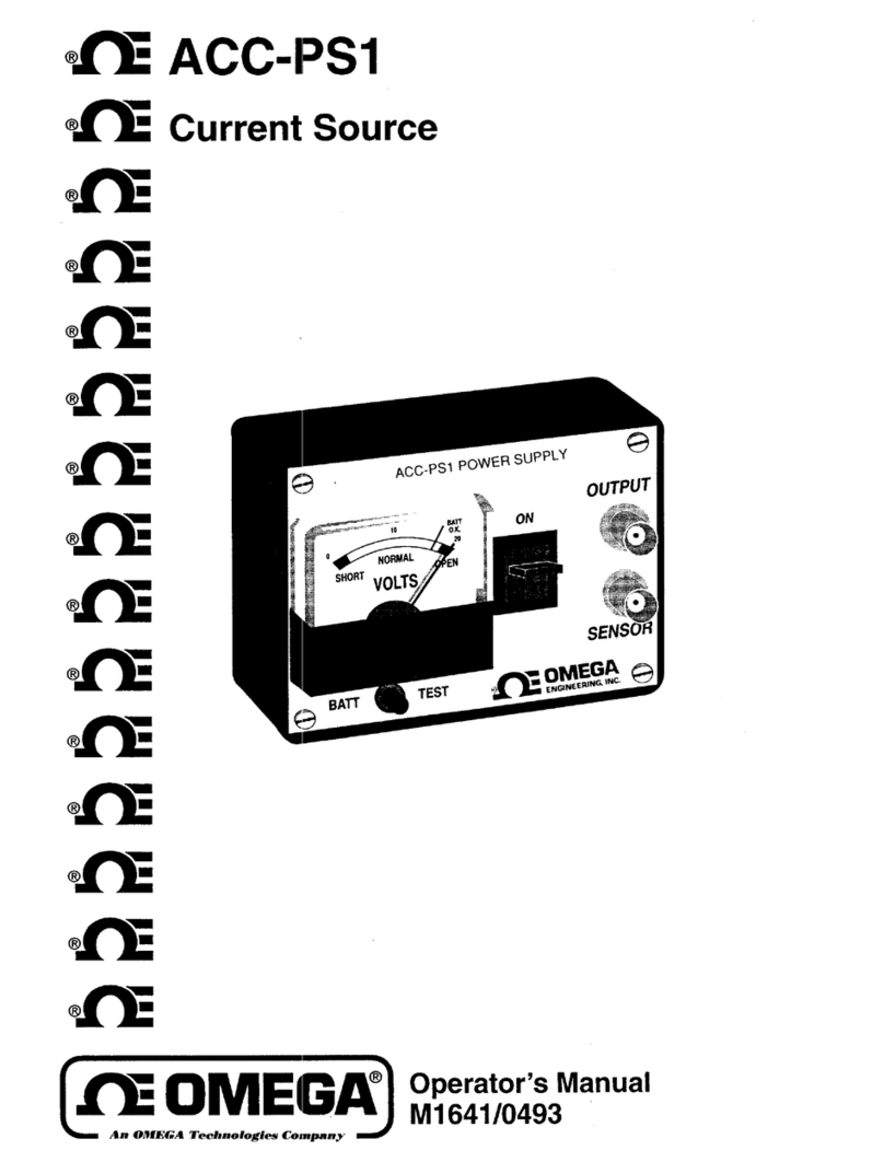
Omega ACC-PS1 User manual

Omega

Omega ACC-PS1 User manual

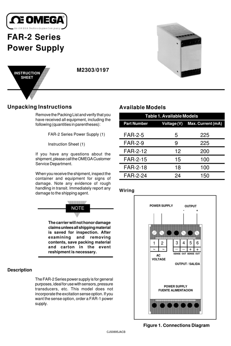
Omega FAR-2 Series User manual

Omega

Omega FAR-2 Series User manual

Omega LDX-4 User manual

Omega

Omega LDX-4 User manual

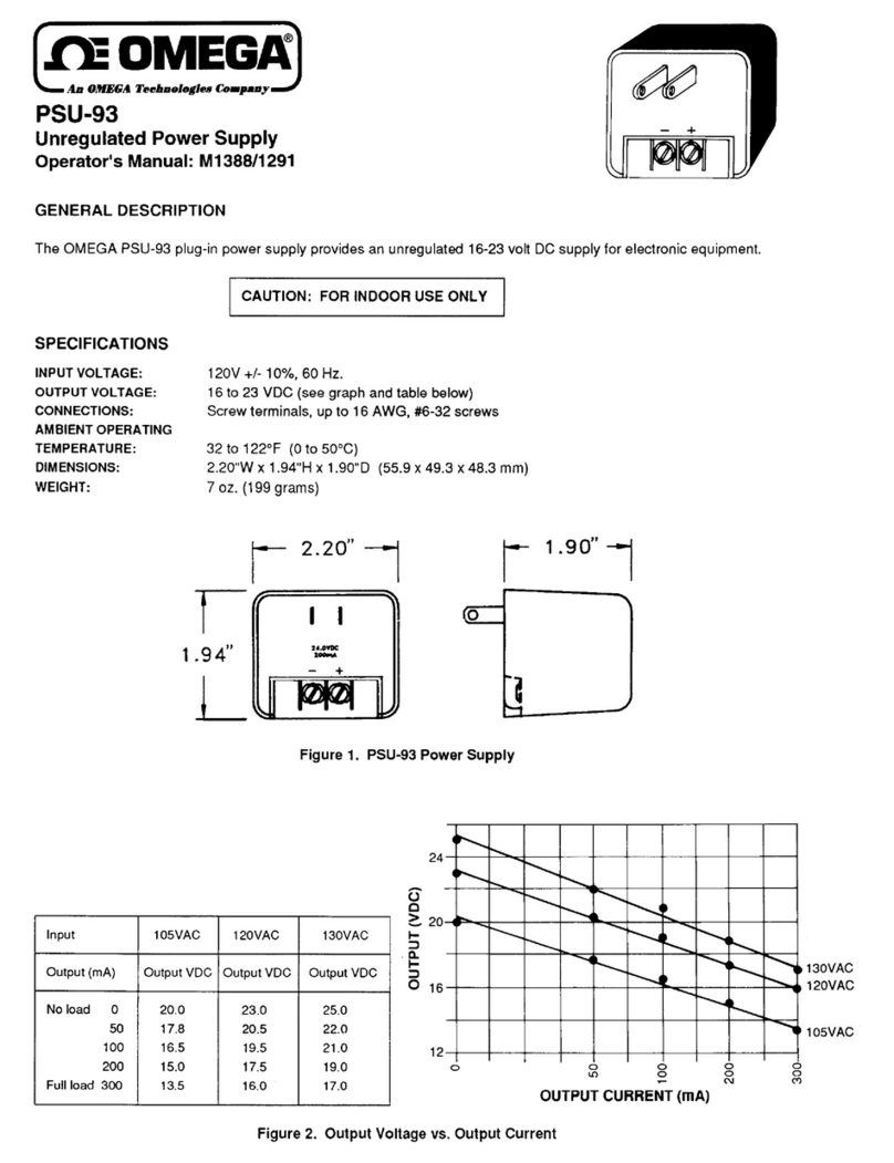
Omega PSU-93 User manual

Omega

Omega PSU-93 User manual

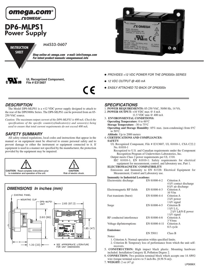
Omega DP6-MLPS1 User manual

Omega

Omega DP6-MLPS1 User manual

Omega DRN-PS-1000 User manual

Omega

Omega DRN-PS-1000 User manual

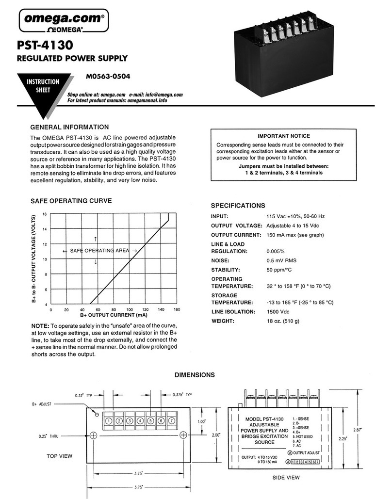
Omega PST-4130 User manual

Omega

Omega PST-4130 User manual

Popular Power Supply manuals by other brands

Ambient ABT-PSC48 user manual

Ambient

Ambient ABT-PSC48 user manual

JVA Z28 Installation and user manual

JVA

JVA Z28 Installation and user manual

Omron S8VM Series product manual

Omron

Omron S8VM Series product manual

Tektronix PWS4000 Series datasheet

Tektronix

Tektronix PWS4000 Series datasheet

Thermaltake W0117 Specifications

Thermaltake

Thermaltake W0117 Specifications

Hama 86514 Operating	 instruction

Hama

Hama 86514 Operating instruction

Manson Engineering Industrial HCS-3300 USB user manual

Manson Engineering Industrial

Manson Engineering Industrial HCS-3300 USB user manual

Lenovo ThinkSystem SR650 quick start guide

Lenovo

Lenovo ThinkSystem SR650 quick start guide

Vertiv 582127200 user manual

Vertiv

Vertiv 582127200 user manual

Athena Power AP-TFX35 user manual

Athena Power

Athena Power AP-TFX35 user manual

JTS PS-510M manual

JTS

JTS PS-510M manual

Bosch PSU-224-DC100 installation manual

Bosch

Bosch PSU-224-DC100 installation manual

Clayton Power LPS II Series Manual and safety instructions

Clayton Power

Clayton Power LPS II Series Manual and safety instructions

Helios Salicru EMi3 user manual

Helios

Helios Salicru EMi3 user manual

Kentec Electronics K25000 Series Installation, commissioning and operating instructions

Kentec Electronics

Kentec Electronics K25000 Series Installation, commissioning and operating instructions

Pulsar R812P quick start guide

Pulsar

Pulsar R812P quick start guide

eta plus ELC N12 Technical documentation

eta plus

eta plus ELC N12 Technical documentation

iseg EPS Series manual

iseg

iseg EPS Series manual

manuals.online logo
manuals.online logoBrands
  • About & Mission
  • Contact us
  • Privacy Policy
  • Terms and Conditions

Copyright 2025 Manuals.Online. All Rights Reserved.