INIM Electronics SmartLevel SPS24060S User manual
Installation manual
SmartLevel
SPS24060S
SPS24160S
Power supply station
Installation manual
EN 54-4
EN 12094-1
0051
1438
0051-CPR-0433
0051-CPR-0434
ISO 9001 Quality Management
certified by BSI with certificate number FM530352

2Copyright
Power supply stations
Copyright
The information contained in this document is the sole property of INIM Electronics s.r.l. No part may be
copied without written authorization from INIM Electronics s.r.l.
All rights reserved.
European directive compliance
This power station has been designed and developed to the highest standards of quality and performance
implemented by INIM Electronics.
This power station must be installed in accordance with the instructions described in this manual and in
compliance with the laws in force.
All power stations from the SmartLevel series are EN54-4 and EN12101-10 compliant.
All power stations from the SmartLevel series, and all accessory items and special functions have IMQ
Sistemi di Sicurezza certification, unless otherwise stated.
Declarations of performance, declarations of compliance and certificates relating to the products mentioned
in this manual can be downloaded from the following website:
www.inim.biz

Installation and programming manual
Table of contents 3
Table of contents
Copyright............................................................................ 2
European directive compliance ............................................... 2
Table of contents.................................................................. 3
Chapter 1 Overview............................................................................. 5
1.1 Application and use 5
1.2 The system parts and definitions 6
1.3 How to use the power supply station 6
1.4 The SmartLevel power supply stations 6
Chapter 2 General information.............................................................. 7
2.1 Supplied documentation 7
2.2 Manual details 7
2.3 Intellectual property rights 7
2.4 Disclaimer 7
2.5 Recommendations 7
2.6 System test 7
2.7 Note to the installer 7
2.8 Technical support 7
2.9 Conventions 8
2.10 CE Mark 9
2.11 Warranty 9
2.12 Safety laws 9
2.13 Replacement and disposal of used devices 10
Chapter 3 Device management........................................................... 11
3.1 Product handling and storage 11
3.2 Unpacking the device 11
Chapter 4 Technical description........................................................... 12
4.1 Station 12
4.2 Internal devices 13
4.3 Signalling LEDs 14
4.4 Technical specifications 15
Chapter 5 Installation instructions....................................................... 16
5.1 Wall mounting 16
5.2 Connecting the mains power source 16
5.3 Connecting the batteries 17
5.4 Thermal probe 18
Chapter 6 Diagnostics and fault solutions ............................................. 19
6.1 Battery disconnected or inefficient 19
6.2 Low Battery 19
6.3 Loop faults and testing 19
6.4 Earth fault 19
Chapter 7 Maintenance ...................................................................... 20

4Table of contents
Power supply stations
Installation manual
Overview 5
Chapter 1
Overview
Note:
The power supply stations described in this manual have been designed and developed to the highest
standards of quality, reliability and performance. The components selected for this product will operate
properly within their specifications when the environmental conditions outside the product enclosure
comply with Class 3k5 (EN 60721-3-3).
1.1 Application and use
The SmartLevel unit is a constituent part of your fire detection system and is capable of supplying power to
the remote loads of the system. It supplies power to remote loads such as: fire-door magnets, sounders,
emergency signs, linear smoke detectors.
Note:
The SmartLevel power supply station is EN54-4 compliant and specifically the amendment EN 54-
4:1997 A2 which includes a test regarding the internal resistance of the batteries.
Main features:
• front panel with signalling LEDs
• 1 24V output
•2faultrelays
• loop connection
The SmartLevel can operate in stand-alone mode using the fault signaling output and on-board data, or
combined mode using the loop of an INIM Electronics fire detection system (refer to Chapter 4 - Technical
description).
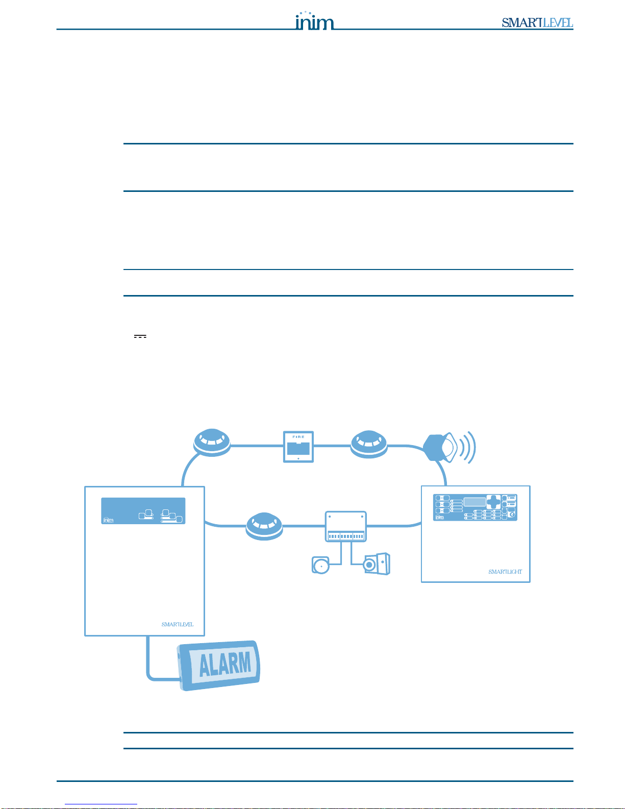
Figure 1 - Example of a typical application
Note:
Do not use this station to supply power to a fire-detection control panel.
Loop supervised by INIM
fire-detection panel
24V output

6Overview
Power supply stations
1.2 The system parts and definitions
Switching power supply: this unit, starting from the mains power supply (230V ) it connects to,
supplies the board with a 24V (27,6V ) stabilized current capable of feeding the control panel and
recharging the batteries. The power-supply module is located below the mother board and is EN54-4
compliant. the mains power supply (230V ) the primary power source of the system. Refer to paragraph
4.2 Internal devices.
Batteries: the secondary power source of the system. The power supply station enclosure houses two lead
batteries @ 12V 7Ah (depending on the model) connected in series. The system monitors the battery
status (efficiency and charge). In the event of inefficient or low battery conditions, the system will signal
fault (A2 amendment). In the event of primary power failure (230V ), the batteries will take over
automatically. If the problem persists for a long period thus causing the battery charge to drop below the
minimum value required, they will be shutdown automatically in order to avoid damage. Refer to paragraph
5.3 Connecting the batteries.
Thermal probe: an accessory tool connected to the panel and attached to the battery pack. This device
monitors the temperature of the battery pack and regulates the battery charge accordingly. Refer to
paragraph 5.4 Thermal probe.
Loop: all the peripheral devices of the system must be connected in parallel to the loop circuit (2 pole
shielded cable). The circuit is considered a "loop" because the wiring path starts at the loop-out terminals,
passes through all the protected areas, connects all the system devices in parallel and returns to the loop-
in terminals. The panel controls and communicates with the loop devices via digital protocol. The loop
utilizes the same two poles for the power supply to the system devices and the two-way communication
channel.
1.3 How to use the power supply station
The power station supplies 24V by means of the “OUTPUT” terminals.
To signal faults are available:
• the “FAULT” relay, which is activated together with the corresponding LED on the panel when the station
detects at least one fault.
• the “MAINS” relay, which is activated together with the corresponding LED on the panel when there is at
least one mains fault.
The loop connection allows the power station to be supervised by the control panel and to report the loop
activity by the LEDs on the front panel.
For details, please refer to and to paragraph 4.2 Internal devices and to paragraph 4.3 Signalling LEDs.
1.4 The SmartLevel power supply stations
Product models:
• SPS24060S - power-supply unit with internal 60W @ 27.6V switching power-supply module and
housing for 7Ah, 12V batteries
• SPS24160S - power-supply unit with internal 160W @ 27.6V switching power-supply module and
housing for 17Ah, 12V batteries

Installation manual
General information 7
Chapter 2
General information
2.1 Supplied documentation
The power supply station comes with a combined installation manual (this document). For further copies of
the installation manual, please contact INIM Electronics offices.
2.2 Manual details
• Title: SPS24060S and SPS24160S installation manual
• Version: 1.50
• Installation manual code: DCMIINIESPS24S
• Addresses: installer, technicians
2.3 Intellectual property rights
The information contained in this document is private property. All rights reserved.
This document must not be reproduced, either totally or in part, without the prior written consent of INIM
Electronics, and refers to the devices specified in paragraph 2.10 CE Mark.
2.4 Disclaimer
INIM Electronics s.r.l. shall not be responsible for damage arising from improper application or use.
Only qualified personnel (refer to Terminology) should touch this device. Installation must be carried out
strictly in accordance with the instructions described herein, and in compliance with the local fire code in
force.
2.5 Recommendations
INIM Electronics recommends that the entire system be checked completely at regular intervals (refer to
paragraph 2.6 System test).
2.6 System test
This system has been designed to provide the highest standards of reliability and performance. Malfunction
of any of the system devices may cause the system to be incapable of reaching the intended levels of
performance. Most problems which prevent the system from operating as intended can be found by regular
testing and maintenance of the system devices (refer to Chapter 7 - Maintenance).
2.7 Note to the installer
In order to provide adequate protection and instructions for correct use of the apparatus, you (the installer)
must be fully aware of the regulations and operating procedures of firefighting. As the only individual in
contact with system users, it is your responsibility to instruct them on how to use this device properly.
2.8 Technical support
Our professional engineers are readily available to assist you. If you require help, call us and you will be put
through to a person capable of answering your questions and providing you with the service you need.
2.9 Conventions
2.9.1 Terminology

8General information
Power supply stations
•Power supply unit: refers to the device defined in paragraph 2.10 CE Mark.
•Left, right, behind, above, below: refer to the directions as seen by the operator in front of the
mounted device.
•Qualified personnel: those persons whose training, expertise and knowledge of the laws and bylaws
regarding service conditions and the prevention of accidents, are able to identify and avoid all possible
situations of danger.
2.9.2 Graphic conventions
Following are the graphic conventions used in the text. For a description of the graphic conventions relating
to the interface, refer to paragraph 4.3 Signalling LEDs.
Note:
The detached notes contain important information about the text.
Attention:
The attention prompts indicate that total or partial disregard of the procedure could damage
the connected devices.
Danger:
The danger warnings indicate that total or partial disregard of the procedure could injure the
operator or persons in the vicinity.
Conventions Example Description
Text in Italics Refer to paragraph 2.9.2
Graphic conventions Text in italics: indicates the title of a chapter, section, paragraph,
table or figure in this manual or other published reference.
[uppercase
letter] [A] Representation of a part of the system or video object.
BUTTON Ok/Esc computer or control panel keys.
Installation manual
General information 9
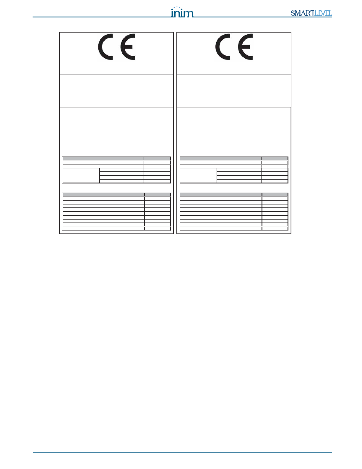
2.10 CE Mark
Figure 2 - Certifications for SmartLevel power stations
For the complete list of the technical specifications, refer to paragraph 4.4 Technical specifications.
Declarations of performance, declarations of compliance and certificates relating to the products mentioned
in this manual can be downloaded from the following website:
www.inim.biz
2.11 Warranty
INIM Electronics s.r.l. warrants that for a period of 24 months from the date of commissioning, the product
shall be free of defects in materials and workmanship. The warranty applies only to defects in parts and
workmanship relating to normal use. It does not cover:
• Improper use or negligence
• Damage caused by fire, flood, wind or lightning
•Vandalism
• Fair wear and tear
INIM Electronics s.r.l. shall, at its option, repair or replace any defective products. Improper use, that is,
use for purposes other than those mentioned in this manual will void the warranty. For the full details and
conditions regarding the warranty, refer to the purchase order.
2.12 Safety laws
The aim of the instructions in this section is to ensure that the device is installed and handled properly. It is
assumed that anyone who handles this apparatus is familiar with the contents of this chapter.
2.12.1 Compliancy
The SmartLevel power supply station has been especially designed and manufactured to comply with EN
54-4 Fire detection and signaling systems - Power supply devices and the amendment EN54-4:1997/
A2:2006 and with EN 12101-10 Smoke and heat control systems - Part. 10: Power supplies.
0051
1438
16
0051-CPR-0434
EN 54-4:1997 + A1:2002 + A2:2006
EN 12101-10:2005
SPS24060S
Apparecchiatura di alimentazione
per sistemi di rivelazione e di segnalazione d'incendio per edifici
e
sistemi per il controllo del fumo e del calore
EN 54-4:1997 + A1:2002 + A2:2006 (NB No. 0051)
Caratteristiche essenziali Prestazione
SSAPenoizatnemilaidenoizatserP
SSAPotnemanoiznufidàtilibadiffA
Durabilità dell'affidabilità
di funzionamento:
SSAPacimretaznetsiser
resistenza alle vibrazioni PASS
SSAPacirtteleàtilibats
resistenza all'umidità PASS
EN 12101-10:2005 (NB No. 1438)
Caratteristiche essenziali Prestazione
SSAPotnemanoiznufidàtilibadiffA
SSAPoidnecni'dosacniinoizatserP
SSAP1.4
elbacilppatoN1.2.5
SSAPatsopsiridopmeT
SSAP1.4
elbacilppatoN1.2.5
SSAP2.2.6
elbacilppatoN1.3.6
0051
1438
16
0051-CPR-0433
EN 54-4:1997 + A1:2002 + A2:2006
EN 12101-10:2005
SPS24160S
Apparecchiatura di alimentazione
per sistemi di rivelazione e di segnalazione d'incendio per edifici
e
sistemi per il controllo del fumo e del calore
EN 54-4:1997 + A1:2002 + A2:2006 (NB No. 0051)
Caratteristiche essenziali Prestazione
SSAPenoizatnemilaidenoizatserP
SSAPotnemanoiznufidàtilibadiffA
Durabilità dell'affidabilità
di funzionamento:
SSAPacimretaznetsiser
resistenza alle vibrazioni PASS
SSAPacirtteleàtilibats
resistenza all'umidità PASS
EN 12101-10:2005 (NB No. 1438)
Caratteristiche essenziali Prestazione
SSAPotnemanoiznufidàtilibadiffA
SSAPoidnecni'dosacniinoizatserP
SSAP1.4
elbacilppatoN1.2.5
SSAPatsopsiridopmeT
SSAP1.4
elbacilppatoN1.2.5
SSAP2.2.6
elbacilppatoN1.3.6
INIM ELECTRONICS S.R.L.
via Dei Lavoratori 10 - fraz. Centobuchi
63076 Monteprandone (AP) - Italy
INIM ELECTRONICS S.R.L.
via Dei Lavoratori 10 - fraz. Centobuchi
63076 Monteprandone (AP) - Italy
10 General information
Power supply stations
2.12.2 Managing electronic devices
The normal motions of any person may generate electrostatic potential of thousands of volts. Discharge of
this current through semiconductor devices during handling may cause serious damage which although
may not be immediately evident may reduce the reliability of the circuits.
If located in their housings, the electronic circuits of INIM Electronics products are highly immune to
electrostatic discharge.
• Do not expose the circuits to damage by removing the modules unnecessarily from their housings.
• When removing or handling the boards, hold the board edges only.
• Do not touch the electronic components, the printed circuits or the metal parts of the connectors.
• Do not hand the board to another person without first ensuring that both of you have the same
electrostatic potential. This can be achieved by simply shaking hands.
• Place the board on an anti-static surface or a conductor surface with the same potential.
Further information regarding procedures relating to safety when working with electronic devices can be
found in EN 61340-5-1 e CLC/TR 61340-5-2.
2.12.3 Setting up the system
In order to provide adequate protection and instructions for proper use, security professionals (Installers
and maintenance technicians) must be familiar with the operating procedure of this device.
Please read the instructions carefully before installing and setting up this product.
Before first power-up, be sure that the earth connection has been completed properly on the respective terminal.
The recommended minimum wire cross section for the earth connection is 2.5 mm
2
, unless otherwise
stated in accessory documentation.
2.13 Replacement and disposal of used devices
Replacement
When replacing obsolete devices, disconnect the devices concerned then complete the connections of the
new devices in compliance with the instructions printed on the respective leaflets.
In order to avoid short-circuits, take all the necessary precautions when removing used batteries.
Disposal
Do not burn used electronic devices, or allow them to pollute the environment (countryside, rivers, etc.).
Electronic devices must be disposed of in a safe environment-friendly way.
When disposing used devices or batteries, contact your local municipal offices for information regarding
their disposal.
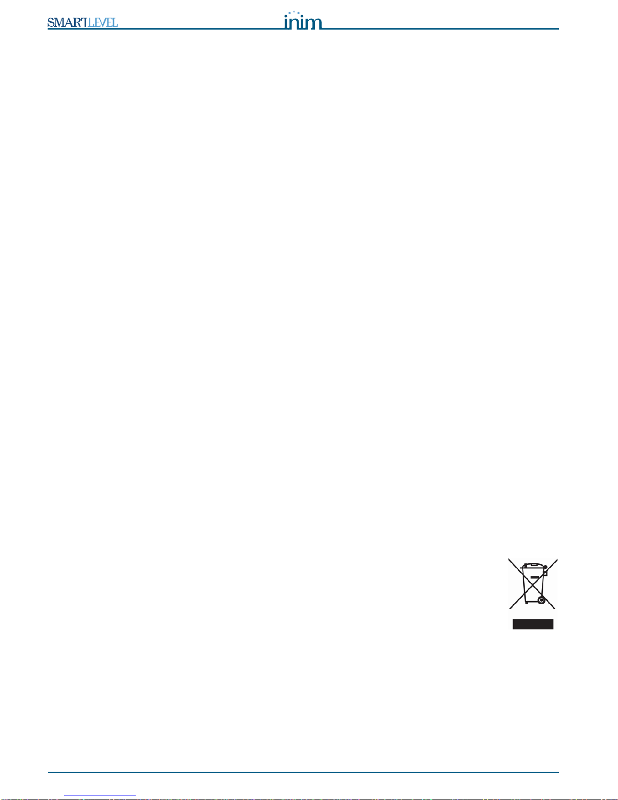
Informative notice regarding the disposal of electrical and electronic equipment
(Applicable in countries with differentiated waste collection systems)
The crossed-out bin symbol on the equipment or on its packaging indicates that the product
must be disposed of correctly at the end of its working life and should never be disposed of
together with general household waste.
The user, therefore, must take the equipment that has reached the end of its working life to the
appropriate civic amenities site designated to the differentiated collection of electrical and
electronic waste.
As an alternative to the autonomous-management of electrical and electronic waste, you can hand over the
equipment you wish to dispose of to a dealer when purchasing new equipment of the same type.
You are also entitled to convey for disposal small electronic-waste products with dimensions of less than
25cm to the premises of electronic retail outlets with sales areas of at least 400m
2
, free of charge and
without any obligation to buy.
Appropriate differentiated waste collection for the subsequent recycling of the discarded equipment, its
treatment and its environmentally compatible disposal helps to avoid possible negative effects on the
environment and on health and favours the re-use and/or recycling of the materials it is made of.

Installation manual
Device management 11
Chapter 3
Device management
3.1 Product handling and storage
This device is safely packed inside a cardboard box, however, care must be taken to avoid accidental
damage during handling. Cartons/boxes should be placed in such a way as to avoid knocks and falls, and
special care must be taken to protect the devices from extreme heat and/or cold.
3.2 Unpacking the device
On receipt the goods must be unpacked with care. All waste packaging materials must be disposed of in
compliance with the local laws and bylaws in force.
The metal enclosure of the device is packed carefully inside the cardboard box.
Note:
The lead batteries are not included. Be sure you have the batteries on hand before starting.
When you remove the four screws and metal-frontplate, you will find:
• The SmartLevel motherboard, mounted on a plastic support which bridges the two sides of the metal
enclosure.
• Power supply module located under the plastic support. The power-supply module is already connected
to the SmartLevel motherboard.
• Thermal probe connected to the power-supply module, for battery-charge optimization.
• A plastic bag containing the battery and earth connection wires.
12 Technical description
Power supply stations
Chapter 4
Technical description
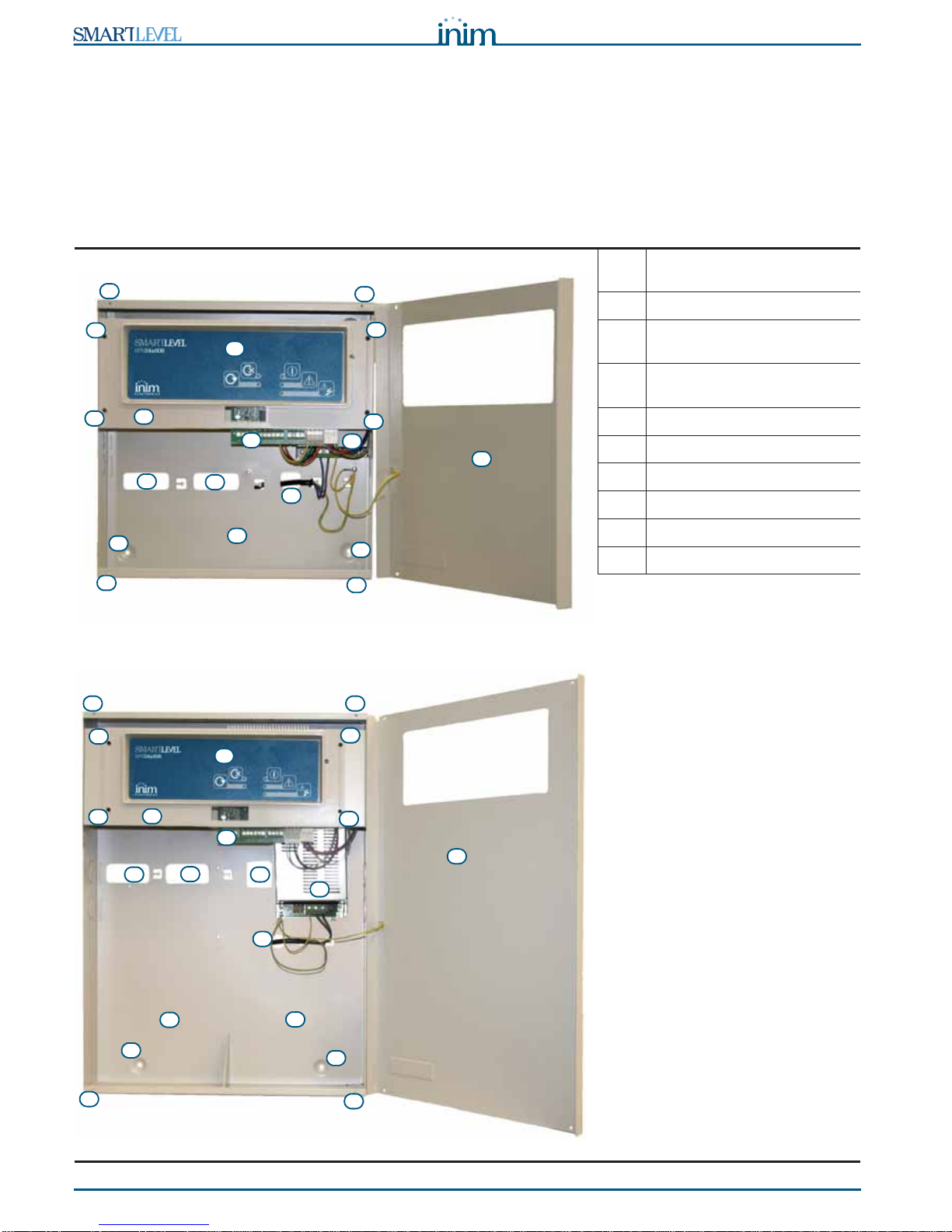
4.1 Station
Figure 3 - Inside SPS24060S
Figure 4 - Inside SPS24160S
[A] Front panel with signaling
LEDs
[B] Front cover
[C] Securing screw location for
the front cover
[D] Plastic support for front panel
and motherboard mounting
[E] Plastic support anchor screw
[F] About the motherboard
[G] Power supply module
[H] Backup battery housing
[I] Cable entry
[J] Anchor screw hole
B
D
H
G
F
E
II
I
J
J
A
C
E
E
E
CC
C
B
D
I
H
G
F
E
I I
I
J
J
A
E
E
E
H
C C
C
C
Installation manual
Technical description 13
4.2 Internal devices
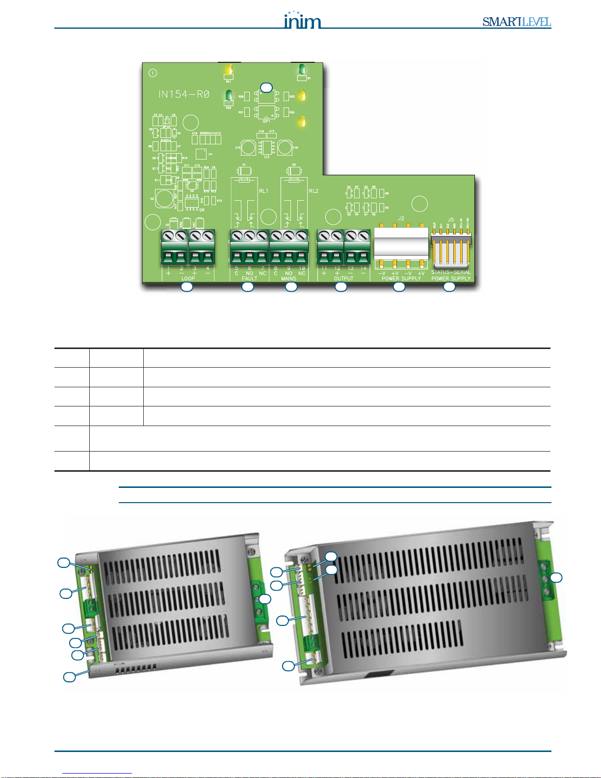
Figure 5 - The SmartLevel motherboard
Main components
Note:
The relay contacts on the electronic are suitable for SELV circuitry only.
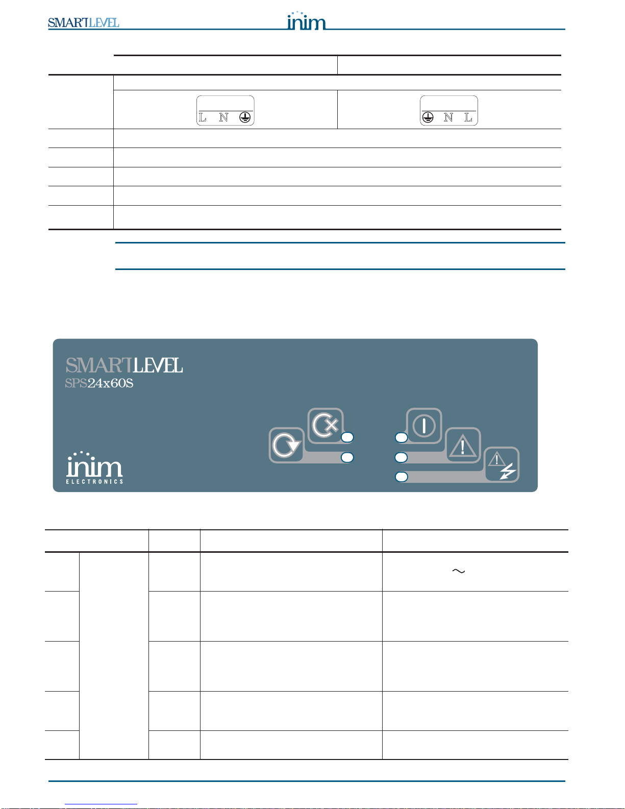
Figure 6 - Switching power supply
The switching power supply is attached to the backplate of the metal enclosure. The power supply type
depends on the station model.
[A] LOOP Loop connection terminals
[B] FAULT Voltage free fault relay contacts
[C] MAINS Voltage free mains fault relay contacts
[D] OUTPUT Output channel terminals (2 “+” terminals and 2 “-” terminals in parallel)
[E] Power-supply module connectors
DO NOT USE
[F] Front panel signaling LEDs
A B C D E E
F
A
A
D
C
B
F
B
C
SPS24060S
power supply SPS24160S
power supply
B
E
FD
B
E
14 Technical description
Power supply stations
Note:
INIM s.r.l. reserves the right to change, replace, in part or entirely, the components not strictly relating
to the installation procedure described in Chapter 5 - Installation instructions.
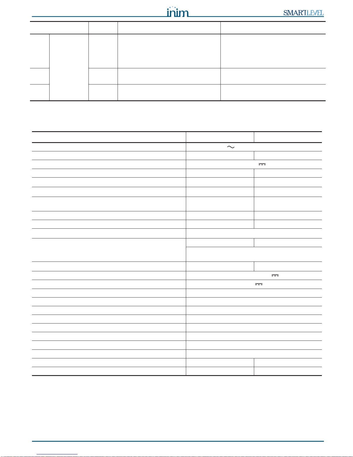
4.3 Signalling LEDs
The user can access the SmartLevel stations through the two relay outputs available on the motherboard
and the LEDs on the front panel and on the switching power supply:
Figure 7 - Front panel
SPS24060S SPS24160S
[A]
Mains input terminal board
[B] SmartLevel mother board connector
[C] Battery connector
[D] Thermal probe connector
[E] Signaling LEDs
[F] Ground fault signaling jumper input
(if the jumper is removed, earth faults will not be signaled)
LED Colour Signalling Note
[A] Frontplate green Indicates the power station is working. This LED will go Off in the event of joint
primary (230V ) and secondary
(batteries) power failure.
[B] yellow Indicates an active fault condition. This condition activates the “FAULT”
relay.
For further details, see the LED
activation on the power-supply unit.
[C] yellow Indicates an active mains fault
condition. This condition activates the “MAINS”
relay.
For further details, see the LED
activation on the power-supply unit.
[D] yellow Indicates an active fault condition or a
short-circuit in the loop. For further details, see the fire-
detection control panel that supervises
the loop.
[E] green Indicates active communication though
the loop.
N
L
230V ~ 50/60 Hz
AC I
nput
NL
230V ~ 50/60 Hz
AC I
nput
B
A
C
D
E
Installation manual
Technical description 15
4.4 Technical specifications
DL1 Power supply
module green Indicates that the power-supply unit is
operating (On). In case of fast blinking the LED
indicates an overheat condition of the
power-supply unit.
In case of slow blinking the LED
indicates an overload of the outputs.
DL2 yellow Indicates an active mains fault
condition. In case of slow blinking the LED
indicates an active earth fault condition.
DL3 yellow Indicates an active battery fault
condition.
Specification SPS24060S SPS24160S
AC power 230 V (-15% / 10%) 50/60 Hz
Maximum current draw 230V 0.5 A 1.1 A
Nominal output voltage 27.6 V
Maximum output current 2.1 A 5.2 A
I
max. a
1.5 A 4 A
I
max. b
1.5 A 4 A
Maximum battery current emission during primary power
failure 1.5 A 4 A
Maximum current for external loads and accessory devices 1.47 A 3.97 A
Maximum battery-charge current 0.6 A 1.2 A
Minimum current (I
min
)30mA
Battery specifications 2 x 12V, 7 Ah 2 x 12V, 17 Ah
2 x 12 V/7 Ah YUASA NP-12 FR or similar with case
flame class UL94-V2 or higher
Maximum internal resistance of the batteries (R
i max
) 2.7 Ohm 1 Ohm
Output voltage from 18 to 27.6V
Battery shutdown tension 19V
Internal fuse of switching power supply module T 3.15A 250V
Maximum output current ripple 1%
Operating temperature (EN 54-4) from -5°C to 40°C
Operating temperature (EN 12101-10) from -5°C to 75°C
Functional class (EN12101-10) A
Environmental class (EN12101-10) 2
Isolation class I
Enclosure protection class (EN 60529) IP42
Dimensions 325 x 325 x 80 mm 497 x 380 x 87 mm
Weight 2.8 Kg 6 Kg
LED Colour Signalling Note

16 Installation instructions
Power supply stations
Chapter 5
Installation instructions
5.1 Wall mounting
1. Pull the wires through the wire entry and ensure they do not get in way of operations.
2. Prepare the wall for the four 8mm anchor screws (stop screws) which must be positioned in
correspondence with the holes on the backplate of the metal enclosure (paragraph 4.1 - [J]).
Danger:
Care must be taken not to drill in the vicinity of electrical wiring, heating ducts and
plumbing.
Note:
Choose anchor screws which are capable of supporting 20kg and which are suitable for the
characteristics of the wall.
Ask for professional advice with regard to the best type of anchor screw for the wall concerned.
3. Using the 4 anchor screws, attach the enclosure securely to the wall.
5.2 Connecting the mains power source
The power system of the SmartLevel stations is EN54-4 compliant.
Danger:
DO NOT power up the system with a non-compliant voltage.
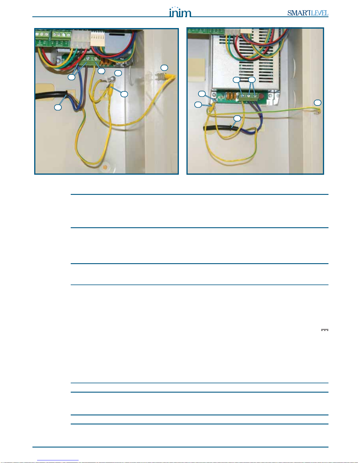
1. Connect the mains power supply to the terminals on the power-supply module (Figure 6 - Switching
power supply, [A] and Figure 8 - Earthing system, [A]).
For a safety standards compliant system, the Line must be connected to terminal “L”, the Neutral
conductor to terminal “N”.
This station must be connected to a separate line on the Electrical Switchboard (Mains power supply).
The line must be protected by a sectioning device which complies with local safety regulations, fire
codes, laws and bylaws in force.
Note:
As a further safety measure, the electrical system of the building must be protected against overload
and short-circuit.
Note:
The ends of wires must not be soft soldered in points where they are subject to clamping.
• Primary power source: 230 V (-15%/+ 10%) 50/60 Hz.
• SPS24060S station current draw: 0.5 A (max.)
• SPS24160S station current draw: 1.1 A (max.)
2. Crimp the earth line wire to the eyelet terminal [B] (included in the package).
3. Attach the wire with the eyelet to the control panel using the ground connection screw [C].
4. Ensure that the terminal “ ” of the power supply module [D] and the frontplate [E] of the enclosure
are connected to earthing system.
Danger:
The protective earthing system must be compliant with the local safety regulations, fire
codes, laws and bylaws in force.
Installation manual
Installation instructions 17
Figure 8 - Earthing system
Note:
A protective earth connection ensures that all exposed conductive surfaces are at the same electrical
potential as the earth surface, in order to avoid the risk of electrical shock if a person touches a device
in which an insulation fault has occurred. In the event of an insulation fault, a protective earth
connection will generate a high fault current which in turn will trigger an overcurrent protection device
(fuse) and disconnect the power supply.
5. Ensure that low-current safety or signal lines DO NOT come into contact with points with potentially
dangerous currents.
Using a plastic cable tie, bunch the wires together and secure them to one of the wire hooks on the
backplate of the enclosure [F].
Note:
The connection wires (to the mains supply and also any other wires inside the SmartLoop enclosure)
must be secured to the cable hooks on the backplate by means of plastic cable ties. Use cable with
double isolation for the connection to the electrical mains.
6. Insert the two 12V batteries and connect them to the power supply module (Figure 6 - Switching power
supply, [C]).
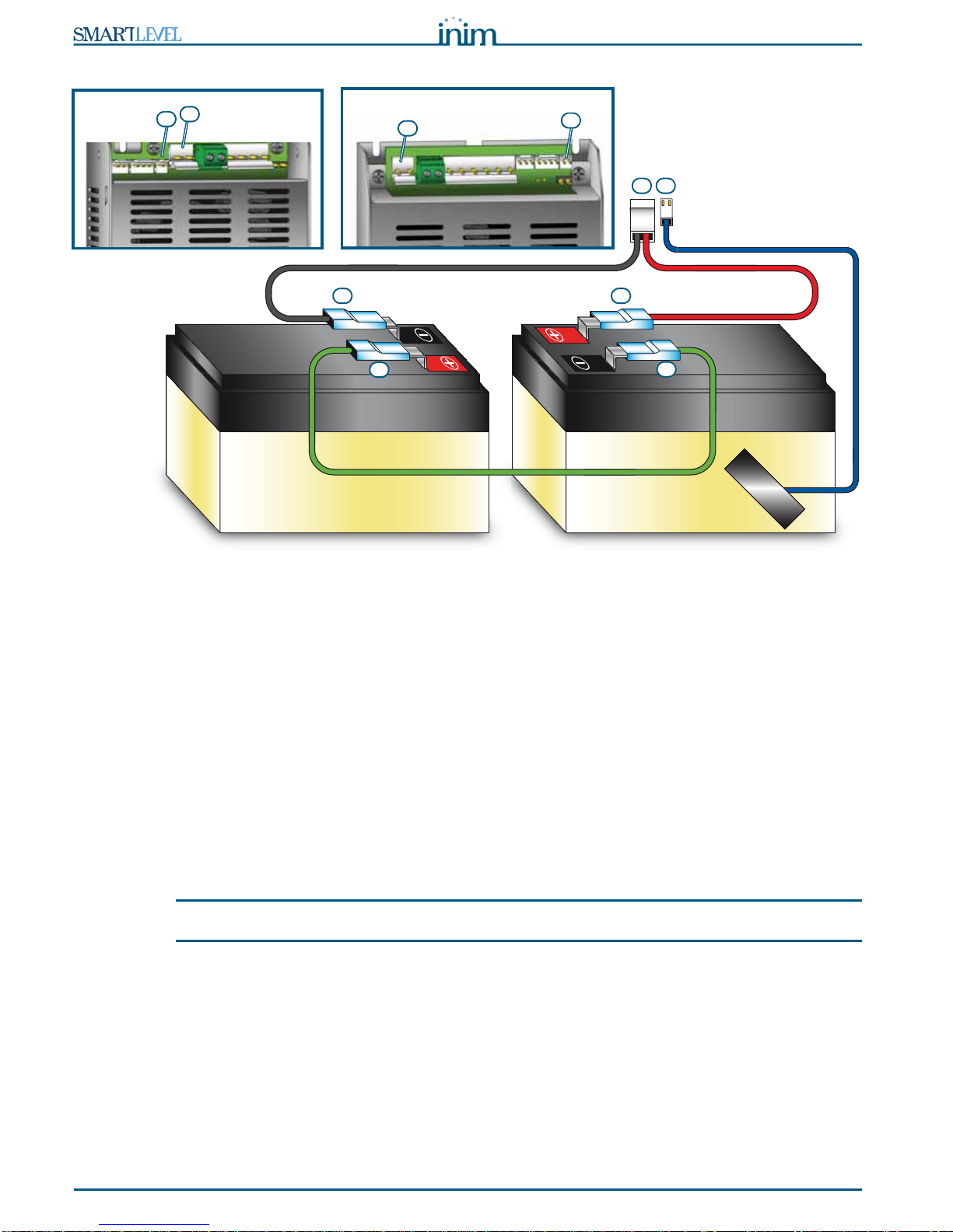
5.3 Connecting the batteries
The enclosure provides housing for two 12V lead batteries: 7 Ah for the SPS24060S model and 17 Ah for
the SPS24160S model. The two batteries must be connected in series, in such way as to provide a 24V
current.
Using the battery connection wire, connect the two batteries together then connect the batteries to the
power-supply module using the respective wire (included).
1. Connect the connection wire [A] to the two batteries.
2. Connect the wire [B] to the batteries.
Attention:
Be sure that cable polarity is correct.
3. Connect the terminal [C] of the battery wire to the proper connector of the power-supply unit (Figure 6
- Switching power supply, [C]).
Attention:
Be sure that connector polarity is correct.
C
SPS24060S
station
E
A
B
D
F
SPS24160S
station
E
A
B
D
F
C
18 Installation instructions
Power supply stations
Figure 9 - Connecting the batteries
The batteries are the secondary power supply of the system. The power supply station monitors the battery
status (efficiency and charge). The battery-test circuit of the power supply station operates as follows:
• Efficiency test
The station tests the battery efficiency every 10 minutes. If their internal resistance is over the allowed
limit, the event will be signaled, according to the amendment EN54-4:1997/A2.
• Battery level test
The battery-test circuit monitors the battery status (efficiency and charge) continuously.
In the event of mains failure, the power supply station will still monitor the battery voltage continuously.
If the voltage drops below 22.8V, the power supply station will signal the fault. Fault condition will be
reseted when the voltage restores to 24.6V.
• Deep discharge shutdown
If a mains failure event lasts for a long period, causing the battery voltage to drop below 18V, the power
supply station will shutdown the batteries in order to avoid permanent damage.
5.4 Thermal probe
Attention:
In order to validate the IMQ-SISTEMI DI SICUREZZA certification and comply with EN 54-4
requirements, installation of a thermal probe is essential.
The thermal probe regulates the charging process in accordance with the battery temperature. The thermal
probe protects against battery overheating and consequent permanent damage.
5.4.1 Connecting the thermal probe
Connect the thermal probe to the proper connector of the power-supply module (Figure 6 - Switching
power supply, [D] and Figure 9 - Connecting the batteries, [D]).
Using adhesive-insulating tape, attach the thermal probe to one of the batteries, in order to provide
optimized heat-transfer measurements.
B B
AA
C D
C
D
SPS24060S
power supply
CD
SPS24160S
power supply

Installation manual
Diagnostics and fault solutions 19
Chapter 6
Diagnostics and fault solutions
6.1 Battery disconnected or inefficient
The battery is not connected or has failed the battery efficiency test (EN 54-4:1997 A2 amendment).
1. Allow the batteries to charge for several hours.
2. If the fault signal persists, disconnect the batteries from the station and test them separately.
3. If only one of the batteries has a voltage below 12.5 - 13 V:
• Replace the faulty battery only.
• Allow the batteries to charge for several hours.
• Check that the fault has cleared.
4. If both batteries have a voltage of 12.5 - 13 V, it means they are both inefficient (even though the
voltage without load is correct).
• Replace both batteries.
• Allow them to charge for several hours.
• Check that the fault has cleared.
6.2 Low Battery
The batteries are running low.
This signal should be present only during primary power source failure (Mains 230V ). Mains power must
be restored in order to charge the batteries.
6.3 Loop faults and testing
The station shows the status of the loop and the presence of any fault or short-circuit on it via the LEDs on
the front panel (Figure 7 - Front panel, [D] and [E]).
For further details, see the analog control panel that supervises the loop.
6.4 Earth fault
In the case of voltage dispersion to earth, this fault is indicated by the LED on the front panel (Figure 7 -
Front panel, [C]) and by a flashing of the “DL2” yellow LED on the power-supply unit (Figure 6 - Switching
power supply, [E]).
This fault signal can be disabled by disconnecting the respective jumper (Figure 6 - Switching power
supply, [F]).

20 Maintenance
Power supply stations
Chapter 7
Maintenance
The following operations must be carried out regularly.
1. Using a damp lint-free cloth, remove any dust that may have gathered on the control panel (do not use
any kind of cleaning product or solvent!).
2. Check the functioning of the LEDs.
3. Check the battery efficiency and change them if necessary.
4. Check the integrity of all wires and connections.
5. Ensure that there are no extraneous objects inside the control panel.
Note:
Points 1 and 2 can be carried out by authorized persons, whereas all other points must be carried out
by qualified technicians.
This manual suits for next models
1
Table of contents
Other INIM Electronics Power Supply manuals

INIM Electronics
INIM Electronics SmartLevel SPS24040 Assembly instructions

INIM Electronics
INIM Electronics SmartLevel SPS24060G Assembly instructions

INIM Electronics
INIM Electronics IPS24060G Instruction Manual

INIM Electronics
INIM Electronics IPS24140 User manual

INIM Electronics
INIM Electronics SmartLevel Series Assembly instructions


