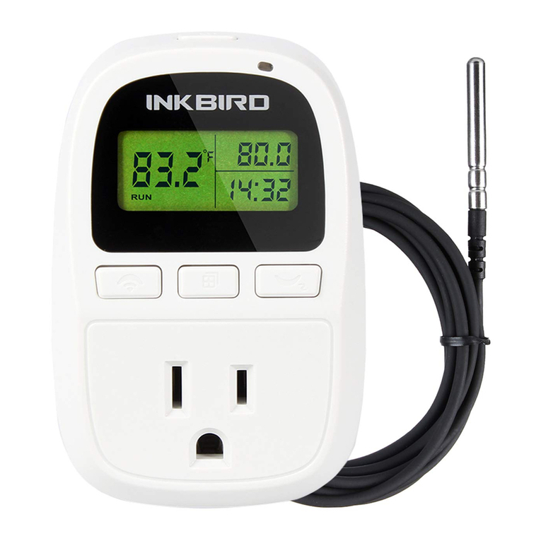
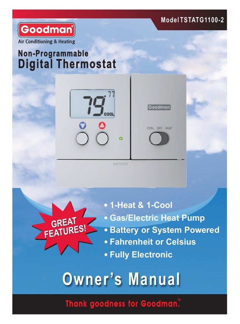
Ink Bird ITC-310T-B User manual

Programmable Outlet Thermostat
Copyright
Copyright©
2016 Inkbird Tech. Co., Ltd. All rights reserved. No part of this document may be reproduced
without prior written permission.
Disclaimer
Inkbird has made every effort to ensure that the information contained in this document is
complete; however, the contents of this document are subject to revision
Inkbird to ensure you have the latest v
Programmable Outlet Thermostat
ITC-310T-B
User Manual
Version 1.0
Inkbird Tech. Co., Ltd.
2016 Inkbird Tech. Co., Ltd. All rights reserved. No part of this document may be reproduced
Inkbird has made every effort to ensure that the information contained in this document is
complete; however, the contents of this document are subject to revision
without notice.
Inkbird to ensure you have the latest v
ersion of this document.
Programmable Outlet Thermostat
2016 Inkbird Tech. Co., Ltd. All rights reserved. No part of this document may be reproduced
Inkbird has made every effort to ensure that the information contained in this document is
accurate and
without notice.
Please contact

Inkbird Tech. Co., Ltd. www.ink
1. Safety Precautions
................................
2. Overview
................................
Main Features
................................
3. Specification
................................
4. Keys Instruction
................................
5. Key Operation Instruction
5.1 ................................
................................
5.2 How to Set Parameters
5.3 Setup Flow Chart
................................
6. Menu Instruction
................................
6.1 Temperature Control Setting
6.1.1 When setting temperature in Centigrade.
6.1.2 W
hen setting temperature in Fahrenheit.
6.1.3 When TR=1 or TR=2.
6.1.4 When setting STA=12, menu codes as below chart.
6.2.1
Temperature setting Range (TS, HD, CD)
6.2.2 Alarm High/Low Limit Setting (AH, AL)
6.2.3 Compressor Delay (PT)
6.2.4 Tempe
rature Calibration (CA)
6.2.5 Display in Fahrenheit or Centigrade unit (CF)
6.2.6 Timer-
Temperature Set Values
6.2.7 Cycle and Auto Mode (MD, AT)
7. Error Description
................................
Sensor fault alarm
................................
8. Technical Assistance and Warranty
8.1 Technical Assistance
................................
8.2 Warranty
................................
ITC-
310T
Inkbird Tech. Co., Ltd. www.ink
2
Contents
................................
................................
................................
................................
................................
................................
................................
................................
................................
................................
................................
................................
................................
................................
................................
5. Key Operation Instruction
................................................................
......................
................................
................................
................................
................................................................
................................
................................
................................
................................
................................
................................
................................
6.1 Temperature Control Setting
................................................................
...............................
6.1.1 When setting temperature in Centigrade.
................................
................................
hen setting temperature in Fahrenheit.
................................
................................
6.1.3 When TR=1 or TR=2.
................................................................
.............................
6.1.4 When setting STA=12, menu codes as below chart.................................
Temperature setting Range (TS, HD, CD)
................................
................................
6.2.2 Alarm High/Low Limit Setting (AH, AL)
................................
................................
6.2.3 Compressor Delay (PT)
................................................................
...........................
rature Calibration (CA)
................................
................................
6.2.5 Display in Fahrenheit or Centigrade unit (CF)
................................
............................
Temperature Set Values
................................
................................
6.2.7 Cycle and Auto Mode (MD, AT)
................................
................................
................................
................................
................................
................................
................................
................................
8. Technical Assistance and Warranty
................................
................................
................................
................................
................................
................................
................................................................
.........................
310T
User Manual
Inkbird Tech. Co., Ltd. www.ink
-bird.com
................................
3
................................
............. 4
................................
......................... 4
................................
........ 5
................................
... 6
......................
7
................................
......... 7
................................
....... 7
................................
............... 8
................................
.. 9
...............................
9
................................
.... 9
................................
.. 10
.............................
10
................................
................... 11
................................
. 13
................................
..... 16
...........................
16
................................
.................. 17
............................
17
................................
................ 17
................................
................ 18
................................
18
................................
................. 18
................................
....... 19
................................
........ 19
.........................
19

Inkbird Tech. Co., Ltd. www.ink
1.
Safety Precautions
Ensure the product using
Do not touch the terminals at least while power is being supplied. Doing so may
occasionally result in injury due to electric shock.
Do not allow pieces of metal, wire clippings, or fine metallic shaving or filings from
installati
on to enter the product. Doing so may occasionally result in electric shock,
fire, or malfunction.
Do not use the product where subject to flammable or explosive gas. Otherwise,
injury from explosion may occasionally occur.
Never disassemble, modify or rep
Electric Shock, fire, or malfunction may occasionally occur.
If the output relays are used over their life expectancy, contact fusing or burning may
occasionally occur. Always consider the application con
relays within their rated load and electrical life expectancy.
ITC-
310T
Inkbird Tech. Co., Ltd. www.ink
3
Safety Precautions
Ensure the product using
within the specification.
Do not touch the terminals at least while power is being supplied. Doing so may
occasionally result in injury due to electric shock.
Do not allow pieces of metal, wire clippings, or fine metallic shaving or filings from
on to enter the product. Doing so may occasionally result in electric shock,
Do not use the product where subject to flammable or explosive gas. Otherwise,
injury from explosion may occasionally occur.
Never disassemble, modify or repair the product or touch any of the internal parts.
Electric Shock, fire, or malfunction may occasionally occur.
If the output relays are used over their life expectancy, contact fusing or burning may
occasionally occur. Always consider the application conditions and use the output
relays within their rated load and electrical life expectancy.
310T
User Manual
Inkbird Tech. Co., Ltd. www.ink
-bird.com
Do not touch the terminals at least while power is being supplied. Doing so may
Do not allow pieces of metal, wire clippings, or fine metallic shaving or filings from
on to enter the product. Doing so may occasionally result in electric shock,
Do not use the product where subject to flammable or explosive gas. Otherwise,
air the product or touch any of the internal parts.
If the output relays are used over their life expectancy, contact fusing or burning may
ditions and use the output

Inkbird Tech. Co., Ltd. www.ink
2. Overview
ITC-310T-B is a dual-relay
outlet thermostat
be set to automatically
contr
This ITC-310T-B can be
mainly used to control temperature during fermentation process of
beer and wine brewing, also widely used in home brewing, aquarium, pet breeding,
hatching, barbecue, boiler tem
pump constant temperature cycle, strain culture fermentation, seed sprouting, electric
heating, electric oven, over
-
system of all kinds of el
ectrical equipment, etc.
This plug-n-play
product with dual relay,
equipment easily to realize ideal temperature control. It’s equipped with dual LED display,
and offers display options of Centigrade and Fah
temperature control. With large output power 1,200W (110V) /2,200W (220V), it’s suitable
for most applications.
ITC-310T-B
is designed with compressor delay protection for refrigeration, high and low
temperature alarm, an
d sensor fault alarm, which makes the temperature controller more
safe and reliable. Functions such as temperature calibration, separately set differential for
refrigeration and heating, enable more accurate temperature control.
Main Features
Programmabl
e, 12 temperatures in 12 periods of time;
Constantly control 12 stages of temperatures by setting it once;
Wide timer setting range: 1~999(min/hr), 1~90(days);
Can be set single or cycle control mode;
Plug and play design, easy to use;
Dual relays, heating
and cooling outputs;
F / C temperature display;
Easy to set, PV and SV dual display screen;;
User calibration;
Delay protection for refrigeration control;
Can be set high and low temperature alarms;
Alarm when over-
temperature and sensor error.
ITC-
310T
Inkbird Tech. Co., Ltd. www.ink
4
outlet thermostat
with programmable
timer function
contr
ol 12 periods timer stages
with different temperature
mainly used to control temperature during fermentation process of
beer and wine brewing, also widely used in home brewing, aquarium, pet breeding,
hatching, barbecue, boiler temperature control, geothermal temperature control, heating
pump constant temperature cycle, strain culture fermentation, seed sprouting, electric
-temperature protection and automatic temperature control
ectrical equipment, etc.
product with dual relay,
can be connected
with refrigeration and heating
equipment easily to realize ideal temperature control. It’s equipped with dual LED display,
and offers display options of Centigrade and Fahrenheit, enabling more humanized
temperature control. With large output power 1,200W (110V) /2,200W (220V), it’s suitable
is designed with compressor delay protection for refrigeration, high and low
d sensor fault alarm, which makes the temperature controller more
safe and reliable. Functions such as temperature calibration, separately set differential for
refrigeration and heating, enable more accurate temperature control.
e, 12 temperatures in 12 periods of time;
Constantly control 12 stages of temperatures by setting it once;
Wide timer setting range: 1~999(min/hr), 1~90(days);
Can be set single or cycle control mode;
Plug and play design, easy to use;
and cooling outputs;
F / C temperature display;
Easy to set, PV and SV dual display screen;;
Delay protection for refrigeration control;
Can be set high and low temperature alarms;
temperature and sensor error.
310T
User Manual
Inkbird Tech. Co., Ltd. www.ink
-bird.com
timer function
, which can
with different temperature
s.
mainly used to control temperature during fermentation process of
beer and wine brewing, also widely used in home brewing, aquarium, pet breeding,
perature control, geothermal temperature control, heating
pump constant temperature cycle, strain culture fermentation, seed sprouting, electric
temperature protection and automatic temperature control
with refrigeration and heating
equipment easily to realize ideal temperature control. It’s equipped with dual LED display,
renheit, enabling more humanized
temperature control. With large output power 1,200W (110V) /2,200W (220V), it’s suitable
is designed with compressor delay protection for refrigeration, high and low
d sensor fault alarm, which makes the temperature controller more
safe and reliable. Functions such as temperature calibration, separately set differential for

Inkbird Tech. Co., Ltd. www.ink
3. Specification
Temperature Control Range
Temperature Resolution
Measuring Accuracy
Temperature Control Mode
Timing Range
Timing Accuracy
Periods of Time
Cycle Setting
Input Voltage
Control Output
Alarm
Sensor Type
Sensor Length
Relay Output
Relay Life
Input Power Cable Length
Dimension
Operating Ambient Temperature
Storage Condition
Warranty
ITC-
310T
Inkbird Tech. Co., Ltd. www.ink
5
Temperature Control Range
-50.0~120 ℃ /-58.0~248 ℉
0.1
℃
(-50.0~99.9
℃
) / 0.1
℉
(-50.0~99.9
1 ℃(100~120℃)/ 1℉(100~248℉)
±1℃ (-50.0 ~ 70℃) / ±2℉ (-
58 ~ 158
On/Off Control, Heat
ing and Cooling
1~999
(
min/hr
),
1~90
(
day
)
24hour±1.7s
Max: 12 periods
1-
999 times cycle, or 00 infinite cycle
100 ~240VAC, 50Hz/60Hz
Current: Max.10A
Voltage: 100~240V AC
Power: Max.1200W(120V)/2200W(220V)
High and Low Temperature Alarm
NTC Sensor(including)
2m / 6.56ft
Cooling(10A,100-240VAC)
Heating(10A,100-240VAC)
Mechanical;Electrical;
1.5m ( 5ft )
140x68x33 mm(body)
Operating Ambient Temperature
-30~ 75 ℃ / -22~ 167℉
Temperature: -20~ 60℃ / -
4~ 140
Humidity: 20~85% (No freeze or moisture
condensation)
1 Year
310T
User Manual
Inkbird Tech. Co., Ltd. www.ink
-bird.com
50.0~99.9
℉
)
58 ~ 158
℉)
ing and Cooling
999 times cycle, or 00 infinite cycle
Power: Max.1200W(120V)/2200W(220V)
4~ 140
℉
Humidity: 20~85% (No freeze or moisture

Inkbird Tech. Co., Ltd. www.ink
4. Keys I
nstruction
① SET Button: P
ress and hold SET
and hold SET button fo
r more than 3 seconds
setting process.
② UP Button:
Under running mode, when TR=1 or 2, press this button can view the
specific stage of the operating;
decrease the setti
ng value.
③ DOWN Button:
Under running mode, when TR=1 or 2, press this button can view the
left working time;
Under setting mode, press this UP button can increase the setting
value.
④ Heating Indicator Light
:
⑤ Cooling Indicator Light
:
status of compressor delay.
⑥
Centigrade/Fahrenheit Reading:
⑦ PV (Process Value):
Under
mode, display menu code.
⑧ SV (Setting Value):
Under
mode, display setting values.
⑨
Heating Device Socket:
⑩
Cooling Device Socket:
ITC-
310T
Inkbird Tech. Co., Ltd. www.ink
6
nstruction
ress and hold SET
button for 3 seconds to enter setting
menu
r more than 3 seconds
to
quit and save the settings during the
Under running mode, when TR=1 or 2, press this button can view the
specific stage of the operating;
Under setting mode, press this DOWN button can
ng value.
Under running mode, when TR=1 or 2, press this button can view the
Under setting mode, press this UP button can increase the setting
:
Light on, heating start working.
:
Light on, cooling start working; light flickering
,
status of compressor delay.
Centigrade/Fahrenheit Reading: Select Celsius or Fahrenheit temperature reading.
Under
normal mode
, display current temperature; Under
mode, display menu code.
Under
normal mode,
display set temperature value; Under setting
mode, display setting values.
Heating Device Socket:
For heating output.
Cooling Device Socket:
For cooling output.
310T
User Manual
Inkbird Tech. Co., Ltd. www.ink
-bird.com
menu
, then press
quit and save the settings during the
Under running mode, when TR=1 or 2, press this button can view the
Under setting mode, press this DOWN button can
Under running mode, when TR=1 or 2, press this button can view the
Under setting mode, press this UP button can increase the setting
,
being in the
Select Celsius or Fahrenheit temperature reading.
, display current temperature; Under
setting
display set temperature value; Under setting

Inkbird Tech. Co., Ltd. www.ink
5. Key O
peration
5.1
When controller works normally, if TR=0, there will be no reaction by shortly
pressing“ ” or “
” button; If TR=1 or 2, short press “
will display the left current working time; short press “
display the specific stage of current working and then return to normal temperature
displaying mode after 3 seconds.
5.2 How to Set Parameters
When controller works normally, press and hold “SET” key for more than 3 seconds to
enter into the mod
ify parameter mode, “ SET” indicator light will on, PV window displaying
the first code ”TS” in menu, if TR=1 or 2, there will be second mode “HD” displaying and
the related setting value displaying in SV window.
Press “SET” button to save the set value an
button can change the current value. After setting, keep pressing “SET” button for 3
seconds at any status will save the changed value and then return to the normal
temperature displaying.
During setting, if th
ere is no operation for 10 seconds, system will automatically quit the
menu and return to the normal temperature displaying mode with automatically save the
modified settings.
ITC-
310T
Inkbird Tech. Co., Ltd. www.ink
7
peration
Instruction
When controller works normally, if TR=0, there will be no reaction by shortly
” button; If TR=1 or 2, short press “ ” button once then release,
will display the left current working time; short press “ ” button once then rele
display the specific stage of current working and then return to normal temperature
displaying mode after 3 seconds.
5.2 How to Set Parameters
When controller works normally, press and hold “SET” key for more than 3 seconds to
ify parameter mode, “ SET” indicator light will on, PV window displaying
the first code ”TS” in menu, if TR=1 or 2, there will be second mode “HD” displaying and
the related setting value displaying in SV window.
Press “SET” button to save the set value and go to next setting, then press “
button can change the current value. After setting, keep pressing “SET” button for 3
seconds at any status will save the changed value and then return to the normal
ere is no operation for 10 seconds, system will automatically quit the
menu and return to the normal temperature displaying mode with automatically save the
310T
User Manual
Inkbird Tech. Co., Ltd. www.ink
-bird.com
When controller works normally, if TR=0, there will be no reaction by shortly
” button once then release,
” button once then rele
ase, will
display the specific stage of current working and then return to normal temperature
When controller works normally, press and hold “SET” key for more than 3 seconds to
ify parameter mode, “ SET” indicator light will on, PV window displaying
the first code ”TS” in menu, if TR=1 or 2, there will be second mode “HD” displaying and
d go to next setting, then press “
” or “ ”
button can change the current value. After setting, keep pressing “SET” button for 3
seconds at any status will save the changed value and then return to the normal
ere is no operation for 10 seconds, system will automatically quit the
menu and return to the normal temperature displaying mode with automatically save the

Inkbird Tech. Co., Ltd. www.ink
5.3 Setup Flow Chart
ITC-
310T
Inkbird Tech. Co., Ltd. www.ink
8
310T
User Manual
Inkbird Tech. Co., Ltd. www.ink
-bird.com

Inkbird Tech. Co., Ltd. www.ink
6. Menu I
nstruction
6.1 Tem
perature Control Setting
6.1.1
When setting temperature in Centigrade.
Symbol Code
TS
Temperature Set
HD
Heating Differential
CD
Cooling Differential
AH
Alarm High Limit
AL
Alarm Low Limit
PT
Compressor Delay
CA
CF
Centigrade/
TR
Timer Setting
ITC-
310T
Inkbird Tech. Co., Ltd. www.ink
9
nstruction
perature Control Setting
When setting temperature in Centigrade.
Function
Setting
Range
Default Setting
Temperature Set
Value
-50.0~120℃ 25.0℃
Heating Differential
Value
0.3~15.0℃ 2.0℃
Cooling Differential
Value
0.3~15.0℃ 2.0℃
Alarm High Limit
-50.0~120℃ 100℃
Alarm Low Limit
-50.0~120℃ -40.0
℃
Compressor Delay
0~10 minutes
0 m
inute
Calibration -15.0~15.0℃
0.0℃
Centigrade/
Fahrenheit C
Timer Setting
0、1or2 0
310T
User Manual
Inkbird Tech. Co., Ltd. www.ink
-bird.com
Default Setting
Remarks
in heating
in cooling
℃
inute
0->off
;
1 or 2->on

Inkbird Tech. Co., Ltd. www.ink
6.1.2 When setting temperature in Fahrenheit.
6.1.3 When TR=1 or TR=2.
Symbol Code
Function
UT
Time Unit Setting
MD
Cycle Setting Mode
AT
Auto Mode
STT
Stage Setting Value
SST
Start Stage Setting
Value
Symbol
Code
Function
TS T
emperature Set Value
HD
Heating Differential
Value
CD
Cooling Differential
Value
AH
Alarm High Limit
AL
Alarm Low Limit
PT
Compressor Delay
CA
Calibration
CF
Centigrade/
Fahrenheit
TR
Timer Setting
ITC-
310T
Inkbird Tech. Co., Ltd. www.ink
10
6.1.2 When setting temperature in Fahrenheit.
Function
Setting Range
Default Sett
Time Unit Setting
D, H, M D
Cycle Setting Mode
0-999 1
Auto Mode
0 or 1 0
Stage Setting Value
1~12 1
Start Stage Setting
Value
1~12 1
Function
Setting Range
Default Setting
emperature Set Value
-50.0~248℉ 77.0℉
Heating Differential
Value
1.0~30.0℉ 3.0℉
Cooling Differential
Value
1.0~30.0℉ 3.0℉
Alarm High Limit
-50.0~248℉ 212℉
Alarm Low Limit
-50.0~248℉ -40.0
℉
Compressor Delay
0~10 minutes
0 minute
Calibration
-15.0~15.0℉ 0.0℉
Centigrade/
Fahrenheit
F
Timer Setting
0、1 or 2 0
310T
User Manual
Inkbird Tech. Co., Ltd. www.ink
-bird.com
Default Sett
ing
Remarks
D: Day
H:Hour
M: Minute
00, Infinite
Cycle
0: Manual
1:Auto
Find the
below chart.
The stage
start to
work.
Default Setting
Remarks
Min unit: 1℉
Min unit: 1℉
Min unit: 1℉
Min unit: 1℉
℉
Min unit: 1℉
0 minute
0-> off ; 1
or 2-> on

Inkbird Tech. Co., Ltd. www.ink
6.1.4 When setting STA=12
, menu codes as below chart.
Symbol Code
Function
S01
Stage 1 Temperature Set
Value
H01
Control Duration
U01
Finished Ala
S02
Stage 2 Temperature Set
Value
H02
Control Duration
U02
Finished Alarm of Stage
S03
Stage 3 Temperature Set
Value
H03
Control Duration
U03
Finished Alarm of St
S04
Stage 4 Temperature Set
Value
H04
Control Duration
U04
Finished Alarm of Stage
S05
Stage 5 Temperature Set
Value
H05
Control Duration
U05
Finished Alarm of Stage
S06
Stage 6 Temperature Set
Value
H06
Control Duration
U06
Finished Alarm of Stage
S07
Stage 7 Temperature Set
Value
ITC-
310T
Inkbird Tech. Co., Ltd. www.ink
11
, menu codes as below chart.
Function
Default Setting
Stage 1 Temperature Set
Value
25.0℃ or 77.0℉
Same setting range as TS.
Control Duration
10
Finished Alarm of Stage
1 n
Stage 2 Temperature Set
Value
25.0℃ or 77.0℉
Control Duration
10
Finished Alarm of Stage
2 n
Stage 3 Temperature Set
Value
25.0℃ or 77.0℉
Control Duration
10
Finished Alarm of Stage
3 n
Stage 4 Temperature Set
Value
25.0℃ or 77.0℉
Control Duration
10
Finished Alarm of Stage
4 n
Stage 5 Temperature Set
Value
25.0℃ or 77.0℉
Control Duration
10
Finished Alarm of Stage
5 n
Stage 6 Temperature Set
Value
25.0℃ or 77.0℉
Control Duration
10
Finished Alarm of Stage
6 n
Stage 7 Temperature Set
Value
25.0℃ or 77.0℉
310T
User Manual
Inkbird Tech. Co., Ltd. www.ink
-bird.com
Remarks
Same setting range as TS.
Note 6.2.6
Note 6.2.6
Note 6.2.6
Note 6.2.6
Note 6.2.6
Note 6.2.6

Inkbird Tech. Co., Ltd. www.ink
H07
Control Duration
U07
Finished Alarm of Stage
S08
Stage 8 Temperature Set
Value
H08
Control Duration
U08
Finished Alarm of Stage
S09
Stage 9 Temperature Set
Value
H09
Control Duration
U09
Finished Alarm of Stage
S10
Stage 10 Temperature
Set Value
H10
Control Duration
U10
Finished Alarm of Stage
S11
Stage 11 Temperature
Set Value
H11
Control Duration
U11
Finished Alarm of Stage
S12
Stage 12 Temperature
Set Value
H12
Control Duration
U12
Finished Alarm of Stage
ITC-
310T
Inkbird Tech. Co., Ltd. www.ink
12
Control Duration
10
Finished Alarm of Stage
7 n
Stage 8 Temperature Set
Value
25.0℃ or 77.0℉
Control Duration
10
Finished Alarm of Stage
8 n
Stage 9 Temperature Set
Value
25.0℃ or 77.0℉
Control Duration
10
Finished Alarm of Stage
9 n
Stage 10 Temperature
Set Value
25.0℃ or 77.0℉
Control Duration
10
Finished Alarm of Stage
10 n
Stage 11 Temperature
Set Value
25.0℃ or 77.0℉
Control Duration
10
Finished Alarm of Stage
11 n
ge 12 Temperature
Set Value
25.0℃ or 77.0℉
Control Duration
10
Finished Alarm of Stage
12 n
310T
User Manual
Inkbird Tech. Co., Ltd. www.ink
-bird.com
Note 6.2.6
Note 6.2.6
Note 6.2.6
Note 6.2.6
Note 6.2.6
Note 6.2.6

Inkbird Tech. Co., Ltd. www.ink
6.2.1 Temperature setting
Range
When controller works normally,
automatically switch
working modes of cooling and heating.
When TR=0
Under normal temperature control mode, w
(Temperature Set Value
)
mode with
cooling indicator lamp
Indicator Light
flickering
protection; w
hen measured temperature
indicator light
off, cooling relay stop wor
When measured temperature
Differential Value)
, entering into
heating relay start working; when measured temperature
Value), heating indicator
light
For example, Set TS=25.0 , CD=2.0 , HD=3.0 : if measured temperature ℃ ℃ ℃
≥27.0 (TS+CD), cooling will turn on; if measured temperature ≤25.0 , cooling will turn ℃ ℃
off.
If measured temperature ≤22.0 (TS℃
≥25.0 , heating will turn off.℃
NOTE:
W
hen TR=0, under plug in or exit setting mode, no need to compare the current measured
temperature with the heating or cooling differential values but only compare directly with
the TS value.
For example, when plug in or exit setting mode, Set TS=25.0
measured temperature>
TS(25.0
cooling will turn off and then return to normal temperature control mode.
If measured temperature
<
≥25.0℃
, heating will turn off and then return to normal temperature control mode.
When TR=1 (Continuous Timer mode)
With this setting, the TS(temperature set value) will be
based on the setting values of S01~S12, H01~H12 and U01~U12.
For example, when periods of time within the range of the control duration of H01, if
measured temperature PV≥(Temperature Set Value )TS1+(Cooling Differenti
then cooling on with cooling indicator light on and cooling relay start working.
About the condition that the interval time between two refrigeration operations shorten
than PT(compressor delay time), please note 6.2.3.
When TR=2 (Target Tim
er mode)
ITC-
310T
Inkbird Tech. Co., Ltd. www.ink
13
Range
(TS, HD, CD)
When controller works normally,
PV screen
displays current measuring temperature,
working modes of cooling and heating.
Under normal temperature control mode, w
hen measured temperature
PV ≥ TS
)
+ CD (Cooling Differential Value
), entering into
cooling indicator lamp
on and cooling relay start working; w
hen the
flickering, cooling device is being in the status of compressor delay
hen measured temperature
PV ≤ TS (
Temperature Set Value
off, cooling relay stop wor
king.
When measured temperature
PV ≤TS (Temperature Set Value)-
HD (Heating
, entering into
heating mode with heating indicator
light
heating relay start working; when measured temperature
PV ≥ TS (
Temperature Set
light
off, heating relay stop working.
For example, Set TS=25.0 , CD=2.0 , HD=3.0 : if measured temperature ℃ ℃ ℃
≥27.0 (TS+CD), cooling will turn on; if measured temperature ≤25.0 , cooling will turn ℃ ℃
If measured temperature ≤22.0 (TS℃
-HD), heating
will turn on; if measured temperature
≥25.0 , heating will turn off.℃
hen TR=0, under plug in or exit setting mode, no need to compare the current measured
temperature with the heating or cooling differential values but only compare directly with
For example, when plug in or exit setting mode, Set TS=25.0
℃, CD=2.0℃
, HD=3.0
TS(25.0
℃
), cooling will turn on; if measured temperature ≤25.0
cooling will turn off and then return to normal temperature control mode.
<
TS(22.0℃
), heating will turn on; if measured temperature
, heating will turn off and then return to normal temperature control mode.
When TR=1 (Continuous Timer mode)
With this setting, the TS(temperature set value) will be
invalid and the controller will work
based on the setting values of S01~S12, H01~H12 and U01~U12.
For example, when periods of time within the range of the control duration of H01, if
measured temperature PV≥(Temperature Set Value )TS1+(Cooling Differenti
then cooling on with cooling indicator light on and cooling relay start working.
About the condition that the interval time between two refrigeration operations shorten
than PT(compressor delay time), please note 6.2.3.
er mode)
310T
User Manual
Inkbird Tech. Co., Ltd. www.ink
-bird.com
displays current measuring temperature,
PV ≥ TS
), entering into
cooling
hen the
Cooling
, cooling device is being in the status of compressor delay
Temperature Set Value
), cooling
HD (Heating
light
on and
Temperature Set
For example, Set TS=25.0 , CD=2.0 , HD=3.0 : if measured temperature ℃ ℃ ℃
≥27.0 (TS+CD), cooling will turn on; if measured temperature ≤25.0 , cooling will turn ℃ ℃
will turn on; if measured temperature
hen TR=0, under plug in or exit setting mode, no need to compare the current measured
temperature with the heating or cooling differential values but only compare directly with
, HD=3.0
℃: if
), cooling will turn on; if measured temperature ≤25.0
℃,
), heating will turn on; if measured temperature
, heating will turn off and then return to normal temperature control mode.
invalid and the controller will work
For example, when periods of time within the range of the control duration of H01, if
measured temperature PV≥(Temperature Set Value )TS1+(Cooling Differenti
al Value) CD,
then cooling on with cooling indicator light on and cooling relay start working.
About the condition that the interval time between two refrigeration operations shorten

Inkbird Tech. Co., Ltd. www.ink
With this setting, the TS(temperature set value) will be out of action and the controller will
work based on the setting values of S01~S12, H01~H12 and U01~U12.
For example, when periods of time within the range of the control duration of H01, if
measured temperature PV≥Temperature Set Value )TS1+(Cooling Differential Value) CD,
then cooling on with cooling indicator light on and cooling relay start working.
NOTE: The control duration of each stage start timing only when the current temperature
rea
ch or drop to the setting temperature in current stage.
About the condition that the interval time between two refrigeration operations shorten
than PT(compressor delay time), please note 6.2.3.
About how to set the timer and control temperature, please no
About the difference between TR=1 and TR=2, please refer to the chart below with 3
stages of the temperature:
Stage X(N=1~12)
STX(X=1~12)(
Stage1
Stage2
Stage3
The difference of the action time as the chart below:
Continuous Timer mode
Time
[minutes]
0
1
2
3
4
5
6
7
8
9
10
11
12
13
14
ITC-
310T
Inkbird Tech. Co., Ltd. www.ink
14
With this setting, the TS(temperature set value) will be out of action and the controller will
work based on the setting values of S01~S12, H01~H12 and U01~U12.
For example, when periods of time within the range of the control duration of H01, if
measured temperature PV≥Temperature Set Value )TS1+(Cooling Differential Value) CD,
then cooling on with cooling indicator light on and cooling relay start working.
NOTE: The control duration of each stage start timing only when the current temperature
ch or drop to the setting temperature in current stage.
About the condition that the interval time between two refrigeration operations shorten
than PT(compressor delay time), please note 6.2.3.
About how to set the timer and control temperature, please no
te 6.2.6.
About the difference between TR=1 and TR=2, please refer to the chart below with 3
STX(X=1~12)(
℃)
HTX(X=1~12)(Minutes)
UAX(X=1~12)
20.0 10
30.0 7
35.0 12
The difference of the action time as the chart below:
TR = 1
Continuous Timer mode
TR = 2
Target Timer mode
Temp
[°C] Stage Temp
[°C]
10
1
10
12
1
12
14
1
14
16
1
16
18
1
18
20
1
20
20
1
20
20
1
20
20
1
20
20
1
20
20
1
20
22
2
20
24
2
20
26
2
20
28
2
20
310T
User Manual
Inkbird Tech. Co., Ltd. www.ink
-bird.com
With this setting, the TS(temperature set value) will be out of action and the controller will
For example, when periods of time within the range of the control duration of H01, if
measured temperature PV≥Temperature Set Value )TS1+(Cooling Differential Value) CD,
then cooling on with cooling indicator light on and cooling relay start working.
NOTE: The control duration of each stage start timing only when the current temperature
About the condition that the interval time between two refrigeration operations shorten
About the difference between TR=1 and TR=2, please refer to the chart below with 3
UAX(X=1~12)
n
n
n
TR = 2
Target Timer mode
Stage
1
1
1
1
1
1
1
1
1
1

Inkbird Tech. Co., Ltd. www.ink
15
16
17
18
19
20
21
22
23
24
25
26
27
28
29
30
31
32
33
34
35
36
37
38
39
ITC-
310T
Inkbird Tech. Co., Ltd. www.ink
15
30
2
22
30
2
24
30
2
26
32
3
28
34
3
30
35
3
30
35
3
30
35
3
30
35
3
30
35
3
30
35
3
30
35
3
32
35
3
34
35
3
35
35
3
35
35
35
35
35
35
35
35
35
35
35
310T
User Manual
Inkbird Tech. Co., Ltd. www.ink
-bird.com
2
2
2
2
2
2
2
3
3
3
3
3
3
3
3
3
3
3
3

Inkbird Tech. Co., Ltd. www.ink
Above chart is the difference between the continuous timer mode and target timer mode,
can be shown as below graph:
The graph show when TR=1, the continuous timer mode as blue line: the current stage
control time of H01~H03 is counted continu
18~29 is 29 minutes; when TR=2, the target timer as red line: the current stage control
time od H01~H03 will only start to count down when the current measured temperature
has been reached the set temperature of curr
32~35 is 39 minutes.
6.2.2 Alarm High/Low Limit Setting (AH, AL)
When measured temperature
temperature <
AH or press any button, then will close the buzzer.
When
measured temperature
temperature >
AL or press any button, then will close the buzzer.
When the buzzer alarming, output of heating or cooling will keep working follow the
settings.
6.2.3
Compressor Delay (PT
Under cooling mode, first time to power on, when measured temperature PV ≥ TS
(Temperature Set Value) + CD (Cooling Differential Value), device won’t start cooling
immediately, but waiting for a delay time
When the interval time between two refrige
device will start cooling immediately
operations is
shorter than the delay time, device will start working until there is no delay
time left.
0
5
10
15
20
25
30
35
40
0123456789
1011
Temperature
ITC-
310T
Inkbird Tech. Co., Ltd. www.ink
16
Above chart is the difference between the continuous timer mode and target timer mode,
can be shown as below graph:
The graph show when TR=1, the continuous timer mode as blue line: the current stage
control time of H01~H03 is counted continuously and total time of 0~10, 11~17 and
18~29 is 29 minutes; when TR=2, the target timer as red line: the current stage control
time od H01~H03 will only start to count down when the current measured temperature
has been reached the set temperature of current stage and total time of 5~14, 19~25 and
6.2.2 Alarm High/Low Limit Setting (AH, AL)
When measured temperature
PV ≥ AH, alarm with “BI-BI-
BIII” sound until the
AH or press any button, then will close the buzzer.
measured temperature
PV ≤ AL, alarm with “BI-BI-
BIII” sound until the
AL or press any button, then will close the buzzer.
When the buzzer alarming, output of heating or cooling will keep working follow the
Compressor Delay (PT
)
Under cooling mode, first time to power on, when measured temperature PV ≥ TS
(Temperature Set Value) + CD (Cooling Differential Value), device won’t start cooling
immediately, but waiting for a delay time
(PT).
When the interval time between two refrige
ration operations is
longer than the delay time,
device will start cooling immediately
.
When the interval time between two refrigeration
shorter than the delay time, device will start working until there is no delay
1011
1213141516171819202122232425262728293031323334353637383940
41
Time [min]
Timer mode CS
Continuous vs. Target mode
310T
User Manual
Inkbird Tech. Co., Ltd. www.ink
-bird.com
Above chart is the difference between the continuous timer mode and target timer mode,
The graph show when TR=1, the continuous timer mode as blue line: the current stage
ously and total time of 0~10, 11~17 and
18~29 is 29 minutes; when TR=2, the target timer as red line: the current stage control
time od H01~H03 will only start to count down when the current measured temperature
ent stage and total time of 5~14, 19~25 and
BIII” sound until the
BIII” sound until the
When the buzzer alarming, output of heating or cooling will keep working follow the
Under cooling mode, first time to power on, when measured temperature PV ≥ TS
(Temperature Set Value) + CD (Cooling Differential Value), device won’t start cooling
longer than the delay time,
When the interval time between two refrigeration
shorter than the delay time, device will start working until there is no delay
41
CS = C
CS = T

Inkbird Tech. Co., Ltd. www.ink
Delay time will
be calculated right after the moment when device stop working.
6.2.4
Temperature Calibration (CA)
When there is
temperature off
user can set
CA for calibration
temperature value.
The calibrated
temperature = the
(positive value, 0 or negative value)
6.2.5
Display in Fahrenheit or Centigrade unit (CF)
Users can select
the temperature reading
the default setting is in
Centigrade.
Fahrenheit, then
set CF to F.
Attentions: when CF value changed, all the setting will be recovered to factory d
setting.
6.2.6 Timer-
Temperature Set Values
U01~U12)
TR:
a value to set timer, set to 0, timer off and set to 1, timer on. When TR=0, timer
function will be off, there will not display the other set values follow TR and no need to set
t
hem; when TR=1 or TR=2, timer function will be activated, user can set the time and the
control temperature values as required, with these settings, TS will be invalid and the the
controller will work based on the set temperature of the timer stages.
UT: a
value to set the time unit, can be set to day, hour or minutes as required.
STT:
a value to set stages of controlled temperature, can be set to max 12 stages: 12
temperature set values and each temperature set value respectively corresponded to a
continuo
us periods of time; when need to control different temperature in different time,
SST can be set to max 12 stages with 12 temperatures as required.
SST:
a value to set start stage to control temperature, can be set to the required stage to
start the temper
ature control.
S01~S12:
values to set the desired controlled temperature, when TR=1, the values of
S01~S012 will replace the TS value as the temperature control values.
H01~H12:
values to set continuous timer, if UT (time unit) set to hour and set H01 to 1
then the controller will control the set temperature of S01 for 12 hours.
U01~U12:
values to set the alarm, set to n=NO Alert; A=Alert; C=Confirm and S=Stop
Program.
UX=n:
if set to n in current stage, when completed the continuous timer, the controlli
will go to the next stage without alarming.
UX=A:
if set to A in current stage , when completed the continuous timer, there will be
alarming with PV screen displaying the current stage value UX(X=01~12) and SV screen
displaying the A in 1Hz flickering.
go to next stage control.
ITC-
310T
Inkbird Tech. Co., Ltd. www.ink
17
be calculated right after the moment when device stop working.
Temperature Calibration (CA)
temperature off
between measured temperature and actual
temperature,
CA for calibration
to get the measured temperature value
same
temperature = the
measured temperature value
+ calibration value
(positive value, 0 or negative value)
Display in Fahrenheit or Centigrade unit (CF)
the temperature reading
in Fahrenh
eit or Centigrade temperature value
Centigrade.
If need to change
the temperature reading in
set CF to F.
Attentions: when CF value changed, all the setting will be recovered to factory d
Temperature Set Values( TR, UT, STT, SST, S01~S12, H01~H12,
a value to set timer, set to 0, timer off and set to 1, timer on. When TR=0, timer
function will be off, there will not display the other set values follow TR and no need to set
hem; when TR=1 or TR=2, timer function will be activated, user can set the time and the
control temperature values as required, with these settings, TS will be invalid and the the
controller will work based on the set temperature of the timer stages.
value to set the time unit, can be set to day, hour or minutes as required.
a value to set stages of controlled temperature, can be set to max 12 stages: 12
temperature set values and each temperature set value respectively corresponded to a
us periods of time; when need to control different temperature in different time,
SST can be set to max 12 stages with 12 temperatures as required.
a value to set start stage to control temperature, can be set to the required stage to
ature control.
values to set the desired controlled temperature, when TR=1, the values of
S01~S012 will replace the TS value as the temperature control values.
values to set continuous timer, if UT (time unit) set to hour and set H01 to 1
then the controller will control the set temperature of S01 for 12 hours.
values to set the alarm, set to n=NO Alert; A=Alert; C=Confirm and S=Stop
if set to n in current stage, when completed the continuous timer, the controlli
will go to the next stage without alarming.
if set to A in current stage , when completed the continuous timer, there will be
alarming with PV screen displaying the current stage value UX(X=01~12) and SV screen
displaying the A in 1Hz flickering. Buzzer will be alarm shortly in every 2 seconds and then
310T
User Manual
Inkbird Tech. Co., Ltd. www.ink
-bird.com
be calculated right after the moment when device stop working.
temperature,
same
as the actual
+ calibration value
eit or Centigrade temperature value
,
the temperature reading in
Attentions: when CF value changed, all the setting will be recovered to factory d
efault
( TR, UT, STT, SST, S01~S12, H01~H12,
a value to set timer, set to 0, timer off and set to 1, timer on. When TR=0, timer
function will be off, there will not display the other set values follow TR and no need to set
hem; when TR=1 or TR=2, timer function will be activated, user can set the time and the
control temperature values as required, with these settings, TS will be invalid and the the
value to set the time unit, can be set to day, hour or minutes as required.
a value to set stages of controlled temperature, can be set to max 12 stages: 12
temperature set values and each temperature set value respectively corresponded to a
us periods of time; when need to control different temperature in different time,
a value to set start stage to control temperature, can be set to the required stage to
values to set the desired controlled temperature, when TR=1, the values of
values to set continuous timer, if UT (time unit) set to hour and set H01 to 1
2,
values to set the alarm, set to n=NO Alert; A=Alert; C=Confirm and S=Stop
if set to n in current stage, when completed the continuous timer, the controlli
ng
if set to A in current stage , when completed the continuous timer, there will be
alarming with PV screen displaying the current stage value UX(X=01~12) and SV screen
Buzzer will be alarm shortly in every 2 seconds and then

Inkbird Tech. Co., Ltd. www.ink
UX=C:
if set to C in current stage, when completed the continuous timer, there ill be
alarming with PV screen displaying the current stage value UX(X=01~12) and SV screen
di
splaying the A in 1Hz flickering. Buzzer will be alarm shortly in every 2 seconds but still
controlling the temperature of current stage, only by pressing any button will go to the
next stage control.
UX=S:
if set to S in current stage,when completed the
alarming with PV screen displaying the current stage value UX(UX=01~12) and SV screen
displaying the A in 1Hz flickering. Buzzer will be alarm shortly in every 2 seconds with all
output control turned off, only by pressing an
6.2.7 Cycle and Auto Mode (MD, AT)
MD: value to set
the operation time of timer and temperature set values, 00:
1~999
: specific time of operation. The default value is 1, means the controller will st
running after a one time operation with the set values.
AT:
value to set the operation mode when re
the controller will stop working when re
setting values by enterin
g the menu, the controller will restart working after re
AT=1: Auto mode. When
there
; when re-plug in, the
controller
plug based on the
operation
rresponding stage.
For example, set
S01(Stage
=0 or A; if there is a 3
hours
hours, in this case, the
controller
re-
plug in, if U01=n or A, the
controller
stop working on Stage 1
with
7.
Error Description
Sensor fault alarm:
when temperature sensor being in short circuit or open loop, the
controller will initiate the mode of sensor fault, and cancel all the
alarming with displaying
ER
normal working mode after remove the sensor fault.
ITC-
310T
Inkbird Tech. Co., Ltd. www.ink
18
if set to C in current stage, when completed the continuous timer, there ill be
alarming with PV screen displaying the current stage value UX(X=01~12) and SV screen
splaying the A in 1Hz flickering. Buzzer will be alarm shortly in every 2 seconds but still
controlling the temperature of current stage, only by pressing any button will go to the
if set to S in current stage,when completed the continuous timer, there ill be
alarming with PV screen displaying the current stage value UX(UX=01~12) and SV screen
displaying the A in 1Hz flickering. Buzzer will be alarm shortly in every 2 seconds with all
output control turned off, only by pressing any button will go to next stage control.
6.2.7 Cycle and Auto Mode (MD, AT)
the operation time of timer and temperature set values, 00:
: specific time of operation. The default value is 1, means the controller will st
running after a one time operation with the set values.
value to set the operation mode when re
-
plug after power off. AT=0: Manual mode,
the controller will stop working when re
-
plug after power off; user need to reset the
g the menu, the controller will restart working after re
there
is a power failure or outage,the timer will
continue
controller
will automatically count the time during
power
operation
time and status of H01~H12 and U01~U12,
then
S01(Stage
1)=25.0C℃, H01=4H, S02(Stage 2) =30.0℃
,
hours
power failure when the controller has worked
controller
will default the 2+3=5 hours to the
operated
controller
will work on Stage 2, if U01=C or S,
the
with
alarming.
Error Description
when temperature sensor being in short circuit or open loop, the
controller will initiate the mode of sensor fault, and cancel all the operations
ER
code. Press a
ny keys can stop the alarm, and return to the
normal working mode after remove the sensor fault.
310T
User Manual
Inkbird Tech. Co., Ltd. www.ink
-bird.com
if set to C in current stage, when completed the continuous timer, there ill be
alarming with PV screen displaying the current stage value UX(X=01~12) and SV screen
splaying the A in 1Hz flickering. Buzzer will be alarm shortly in every 2 seconds but still
controlling the temperature of current stage, only by pressing any button will go to the
continuous timer, there ill be
alarming with PV screen displaying the current stage value UX(UX=01~12) and SV screen
displaying the A in 1Hz flickering. Buzzer will be alarm shortly in every 2 seconds with all
y button will go to next stage control.
the operation time of timer and temperature set values, 00:
infinite cycle;
: specific time of operation. The default value is 1, means the controller will st
op
plug after power off. AT=0: Manual mode,
plug after power off; user need to reset the
g the menu, the controller will restart working after re
-plugged.
continue
to work
power
off and re-
then
run to the co
,
H02=6H, U02
on Stage1 for 2
operated
time; when
the
controller will
when temperature sensor being in short circuit or open loop, the
operations
. Buzzer
ny keys can stop the alarm, and return to the

Inkbird Tech. Co., Ltd. www.ink
8.
Technical Assistance
8
.1 Technical Assistance
If you have any problems installing or using this thermostat, please carefully and
thoroughly review the instruction manual. If you require assi
We will reply your emails in 24 hours from Monday through Saturday.
You can also visit our web site
technical questions.
8.2 Warranty
INKBIRD TECH. C.L. warrants this thermostat for one years from
when operated under normal condition by the original purchaser (not transferable), against
defects caused by INKBIRD’s workmanship or materials. This warranty is limited to the
repair or replacement, at INKBIRD’s discretion, of all or
original receipt is required for warranty purposes.
INKBIRD is not responsible for injury property damage or other consequential damages or
damages of third parties arising directly from an actual or alleged in mater of workman
of the product.
There are no representations, warranties, or conditions, express or implied, statutory or
otherwise, other than herein contained in the sale of goods act or any other statue.
ITC-
310T
Inkbird Tech. Co., Ltd. www.ink
19
Technical Assistance
and Warranty
.1 Technical Assistance
If you have any problems installing or using this thermostat, please carefully and
thoroughly review the instruction manual. If you require assistance, please write us to
We will reply your emails in 24 hours from Monday through Saturday.
You can also visit our web site
www.ink-bird.com to find the ans
wers of the common
INKBIRD TECH. C.L. warrants this thermostat for one years from
the date of purchase
when operated under normal condition by the original purchaser (not transferable), against
defects caused by INKBIRD’s workmanship or materials. This warranty is limited to the
repair or replacement, at INKBIRD’s discretion, of all or
part of the thermostat. The
original receipt is required for warranty purposes.
INKBIRD is not responsible for injury property damage or other consequential damages or
damages of third parties arising directly from an actual or alleged in mater of workman
There are no representations, warranties, or conditions, express or implied, statutory or
otherwise, other than herein contained in the sale of goods act or any other statue.
Business Contact:
sales
Technical Support:
cs@
Business Hours: 09:00-
18:00(GMT+8) from Monday to Friday
URL:
www.ink
310T
User Manual
Inkbird Tech. Co., Ltd. www.ink
-bird.com
If you have any problems installing or using this thermostat, please carefully and
stance, please write us to
We will reply your emails in 24 hours from Monday through Saturday.
wers of the common
the date of purchase
when operated under normal condition by the original purchaser (not transferable), against
defects caused by INKBIRD’s workmanship or materials. This warranty is limited to the
part of the thermostat. The
INKBIRD is not responsible for injury property damage or other consequential damages or
damages of third parties arising directly from an actual or alleged in mater of workman
ship
There are no representations, warranties, or conditions, express or implied, statutory or
otherwise, other than herein contained in the sale of goods act or any other statue.
Contact Us
sales
@ink-bird.com
cs@
ink-bird.com
18:00(GMT+8) from Monday to Friday
www.ink
-bird.com
Table of contents
Other Ink Bird Thermostat manuals
