InMode Morpheus8 User manual

Morpheus8 System
Operator Manual
Version: DO609736B

Operator Manual: Morpheus8 System
DO609736B
Copyright © InMode Ltd.
Date: December 2020
All rights reserved. Contents of this publication may not be reproduced in any form
without the written permission of InMode Ltd.
🏭InMode Ltd
Tavor House. POB 533, Industrial Park South,
Yokneam, 2069206. Israel
Tel: +972-4-9096313
Fax: +972-4-9096310

Table of Contents
Section 1: Introduction ............................................................................................. 1
1.1 Before You Start..................................................................................................... 1
1.2 System Overview.................................................................................................... 1
1.3 Conventions Used in the Manual........................................................................... 1
1.4 Explanation of the Symbols used on the System................................................... 2
Section 2: Safety....................................................................................................... 3
2.1 The Patient............................................................................................................. 3
2.2 Treating Attendant................................................................................................. 3
2.3 Cautions ................................................................................................................. 4
2.4 Electrical and Mechanical Safety ........................................................................... 4
2.5 Fire Hazards............................................................................................................ 4
2.6 Safety Features of the System ............................................................................... 5
2.7 Safe use of the Active Accessories......................................................................... 5
2.8 Warnings ................................................................................................................ 6
2.9 System and Handpieces Labels .............................................................................. 7
2.10 Equipment Classification...................................................................................... 10
Section 3: System Installation................................................................................. 11
3.1 Electrical Requirements ....................................................................................... 11
3.2 Environmental Requirements .............................................................................. 11
3.3 Equipment List ..................................................................................................... 11
3.4 Unpacking............................................................................................................. 12
3.5 Installation ........................................................................................................... 13
3.6 Moving the System .............................................................................................. 13
3.7 System Disposal ................................................................................................... 13
Section 4: Device Description.................................................................................. 14
4.1 Rear Panel ............................................................................................................ 14
4.2 Front panel........................................................................................................... 14
4.3 Top Panel.............................................................................................................. 15
4.4 Software Screens.................................................................................................. 16
4.5 Sound Indicator.................................................................................................... 20
4.6 Handpieces........................................................................................................... 20
Section 5: System Operation................................................................................... 23
5.1 Device Start-Up .................................................................................................... 23
5.2 System Shutdown ................................................................................................ 23
Section 6: Morpheus8 Treatment Information ........................................................ 24
6.1 Sub-dermal Fractional Treatment........................................................................ 24

6.2 Indications for Use ............................................................................................... 24
6.3 Contraindications................................................................................................. 24
6.4 Possible Adverse Side Effects............................................................................... 26
6.5 Pre-treatment Recommendations....................................................................... 26
6.6 Test Spots............................................................................................................. 27
6.7 Treatment Recommendations ............................................................................. 29
6.8 Treatment Schedule............................................................................................. 30
6.9 Post-treatment Recommendations ..................................................................... 31
Section 7: Troubleshooting ..................................................................................... 32
7.1 Description of Faults with All Handpiece............................................................. 32
Section 8: System Specifications ............................................................................. 33
8.1 Output Power Curves........................................................................................... 34
8.2 EMC Safety........................................................................................................... 35
Table from IEC60601-1-2, / 5.2.2.1 C&F ............................................................ 39

Morpheus8 System Operator Manual
Section 1: Introduction
1 of 39
Section 1: Introduction
1.1 Before You Start
The manual and the equipment are for use only by qualified medical professionals
trained in the particular technique to be performed.
Federal (USA) law restricts sale of this device by or on the order of a physician.
Read this manual to become familiar with all safety requirements and operating
procedures before attempting to operate the System.
1.2 System Overview
The InMode RF Pro Platform with the Morpheus Handpieces marketed as Morpheus8
System and employs bi-polar Radio-frequency (RF) technology for use in
dermatologic and general surgical procedures for electrocoagulation and hemostasis
for various aesthetic applications. The device provides individual adjustment of
treatment parameters to achieve maximum efficiency and safety for each patient
and applications.
1.3 Conventions Used in the Manual
The following conventions in the form of notes and warnings are used in this manual:
WARNING! This information is extremely important!
ATTENTION! Consult Accompanying Document.
NOTE! Provides general information that is important to keep in mind.

Morpheus8 System Operator Manual
Section 1: Introduction
2 of 39
1.4 Explanation of the Symbols used on the System
Symbol
Description
CSA marking
(212603 CSA master contract number)
Do not discard in trash. Electronic equipment should be
disposed of in an appropriate manner
Fuse
Type BF Equipment
HF Isolated Patient Circuit
Follow the operating instructions
Federal (US) law restricts this device to sale by the order
of a physician licensed by the law of the state in which
he practiced to use or order the use of the device
Do not reuse/single use only. This symbol is used for
disposable one-time-use products.
This equipment intentionally supplies non-ionizing RF
energy
Sterilized by Radiation
Table 01-1: Device Symbols

Morpheus8 System Operator Manual
Section 2: Safety
3 of 39
Section 2: Safety
This chapter describes safety issues regarding the use and maintenance of the
Morpheus8 System, with a special emphasis on electrical safety.
The applicator is designed for safe and reliable treatment when used in accordance
with proper operation and maintenance procedures. Only trained, qualified
practitioners can use the system and the applicator. The operator and all other
personnel operating or maintaining the system should be familiar with the safety
information provided in this section.
The primary consideration should be to maximize safety for both treating attendant
and patient.
Read this chapter to be familiar with all its safety requirements and
operating procedures prior to system operation.
RF energy can cause injury if used improperly.
High voltage is present inside the System.
Always be aware of the possible dangers and take proper safeguards as
described in the manual.
2.1 The Patient
▪Well-trained staff is key for assuring patient safety. A patient history report
should be completed prior to scheduling. Patients should be fully informed of the
treatment details, the likely results and any risks associated with the treatment.
▪Jewelry and metal accessories that are within the activation range of the System
should be removed to avoid accidental RF conduction.
▪Patients will not be in contact with any metal or other alternate pathway to
ground whilst the System is in use.
2.2 Treating Attendant
▪Only authorized individuals with appropriate training and knowledge should
operate, assist in the operation of, or provide maintenance to the Morpheus8
System.

Morpheus8 System Operator Manual
Section 2: Safety
4 of 39
▪Personnel should not operate the System until they have been fully educated in
its use. Make sure that all treatment personnel are familiar with the System
controls and know how to shut down the System instantly.
▪There are no user-serviceable parts in the System, and all service and repair must
be performed only by the factory or authorized field service technicians.
2.3 Cautions
The following cautions should be heeded for safe System use:
▪Do not touch the System’s inner parts.
▪Service is supplied by company authorized personal only.
▪To avoid damage, do not allow the Handpieces to come in contact with hard
materials.
2.4 Electrical and Mechanical Safety
▪Keep all covers and panels of the System closed. Removing the covers creates a
safety hazard.
▪Keep hands away from the applicator during the System start-up.
▪Perform maintenance procedures when the System is shut down and
disconnected from the power.
▪The System is grounded through the grounding conductor in the power cable.
This protective grounding is essential for safe operation.
▪Move the System slowly and carefully. The System weighs approximately 15kg
(33 lb.) and may cause injury if proper care is not used when moving it.
▪Provide as much distance as possible between the System, RF Handpieces and
other electronic equipment as the activated RF generator may cause interference
between them.
2.5 Fire Hazards
▪Materials conducting RF energy may cause temperature rise of the absorbing
material. Do not use the System in the presence of explosive or flammable
materials conductive to RF.
▪Do not use flammable substances when preparing the skin for treatment. Be
especially careful with the use of oxygen.

Morpheus8 System Operator Manual
Section 2: Safety
5 of 39
▪Keep drapes and towels moist to prevent them from igniting and burning. Use
nonflammable prepping solutions.
▪If alcohol is used for cleaning and disinfecting, it must be allowed to dry
thoroughly before the System is used.
▪Do not use the System in the presence of explosive or flammable materials.
2.6 Safety Features of the System
The System incorporates the following safety features. All personnel operating the
System should be familiar with these features.
▪The System has unique password to avoid device operation by non-authorized
personnel.
▪The power electronics cannot be activated unless the applicator and Footswitch
have been connected to the System.
▪An audible tone indicates energy activation.
▪During activation, the System performs a self-test of the hardware.
▪Hardware is tested every 10ms to ensure proper operation of electrical circuit.
▪The System starts at a low setting.
2.7 Safe use of the Active Accessories
▪Examine the connection of the Handpieces through the connectors to the System
before using. Ensure that the accessory functions as intended. Improper
connection may result in arcs and sparks, accessory malfunction, or unintended
treatment effects.
▪Do not wrap the Handpieces cords around metal objects. It may induce current
that could lead to electrical shocks, fire or injury to the patient or personnel.
▪The tips are for single use only. Do not try to reuse them. Re-use of the tips may
cause for unintended cross contaminations and infections, create loss of integrity
that may affect the performance and make the Device non-functional.
Do not connect a wet accessory to the System.
Do not immerse the applicator under water at any time.

Morpheus8 System Operator Manual
Section 2: Safety
6 of 39
2.8 Warnings
This equipment is for use only by qualified medical professionals trained in
the particular technique to be performed.
Only Handpieces manufactured or approved by InMode Ltd. should be used
with Morpheus8 System.
Connect the power cord to a properly polarized and grounded power
source with the frequency and voltage characteristics that match those
listed on the back of the unit.
Connect the System power cord to a properly grounded receptacle. Do not
use power plug adapters.
Always turn off and unplug the device before cleaning.
The patient should not come into contact with metal parts which are
earthed or which have an appreciable capacitance to earth. The use of
antistatic sheeting is recommended for this purpose. Treatment bed or
chair should not be electric.
Use the lowest output setting necessary to achieve the desired treatment
effect. The higher RF is applied, the greater the possibility of unintended
thermal damage.
Failure of the equipment could result in an unintended increase of output
power.
The cables of the Handpieces should be positioned in such a way that
contact with the PATIENT or other leads is avoided.
Fire / Explosion Hazard - The following substances will contribute to
increased fire and explosion hazards in the operating room:
–Flammable substances (such as alcohol-based skin prepping agents and
tinctures).
–Naturally occurring flammable gases which may accumulate in body
cavities such as the bowel.
–Oxygen enriched atmospheres.
–Oxidizing agents (such as nitrous oxide [N2O] atmospheres).
–Endogenous gases.

Morpheus8 System Operator Manual
Section 2: Safety
7 of 39
The RF energy and heating associated with the System can provide an
ignition source. Observe fire precautions at all times. When using
Morpheus8 System in the same room with any of these substances or
gases, prevent their accumulation or pooling within the area where
Morpheus8 procedures are performed.
The operation of the Morpheus8 System may adversely influence the
operation of other electronic EQUIPMENT.
To avoid the RISK of electric shock, this equipment must only be connected
to a SUPPLY MAINS with protective earth.
Do not use Morpheus8 on patients with pacemakers or internal
defibrillators.
2.9 System and Handpieces Labels
As required by national and international regulatory agencies, appropriate warning
and information labels have been attached in specific locations on the instrument as
identified below.
Figure 2-1: Morpheus8 System Rear Panel with Labels

Morpheus8 System Operator Manual
Section 2: Safety
8 of 39
Figure 2-2: Device label
Figure 2-3: Footswitch label
The Handpieces certifications and identification labels are attached to connectors on
the Handpieces. It states that the product conforms to the performance standards,
and indicates the manufacturer’s name, date of manufacturing, model and serial
number of the Handpiece. The following labels are located on the Handpiece:
Manufacturer identification labeling is placed on the Handpieces:
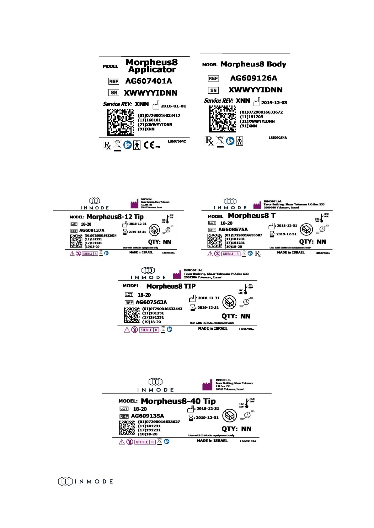
Morpheus8 System Operator Manual
Section 2: Safety
9 of 39
Figure 2-4: Morpheus8 Applicator(left) and Morpheus8 Body (right) Identification Labels
Figure 2-5: Morpheus8 Tip Identification Label
Figure 2-6: Morpheus8 Body Tip Identification Label

Morpheus8 System Operator Manual
Section 2: Safety
10 of 39
2.10 Equipment Classification
The following is a list of the different equipment used and their classifications.
▪Electric shock protection: Class I, Type BF for the RF Handpieces.
▪Protection against ingress of liquids: Ordinary equipment.
▪Not suitable for use in presence of flammable substance.
▪Power receptacle must include protective earth and must be checked before
connecting the System.
The Morpheus8 System is classified as Class II device defined by the FDA CDRH and
complies with 21 CFR subparts E.

Morpheus8 System Operator Manual
Section 3: System Installation
11 of 39
Section 3: System Installation
3.1 Electrical Requirements
▪The System will require a separate line supply of single phase (100Vac; 10A) or
(115Vac; 10A) or (230Vac; 10A) or (240Vac; 10A) 50-60Hz.
▪Power receptacles must be within 15 feet of the System site.
▪The System should not share a power line with other equipment.
▪Power receptacle must include protective earth and must be checked before
connecting the System.
For continued protection against fire, replace the fuse only with one of the
same type and rating.
Proper grounding is essential for safe operation.
3.2 Environmental Requirements
▪Corrosive materials can damage electronic parts; therefore, the System should
operate in a non-corrosive atmosphere.
▪For optimal operation of the System, maintain room temperature between
20º-27ºC (68º-79ºF) and relative humidity of less than 80%.
3.3 Equipment List
The System includes the following:
▪System platform
▪One or more hand pieces
▪Foot switch
▪Cradle
▪Operator manual
▪Power cord
Morpheus8 System Operator Manual
Section 3: System Installation
12 of 39
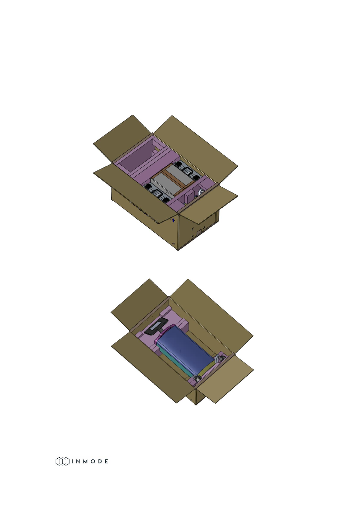
3.4 Unpacking
In order to unpack the device:
1. Remove the paper strip and open the box
2. Remove accessories and foams around the device.
3. Take device out of the box using top and bottom handles.

Morpheus8 System Operator Manual
Section 3: System Installation
13 of 39
3.5 Installation
The System is designed for installation in a clinic environment. To install the System,
perform the following tasks:
▪Check the System and all its components for damage.
▪Connect cradle to the device.
▪Connect Handpiece to the connector and place into the cradle.
▪Connect the Footswitch.
▪Connect the power cord to the System inlet.
▪Plug the System Power Cord into an appropriate electrical outlet.
3.6 Moving the System
▪Turn the System off.
▪Disconnect the Power Cord.
▪Disconnect the Handpieces.
▪Disconnect the Footswitch.
▪Release the Wheel Brakes.
▪Slowly push or pull the System using the handle.
▪When moving the System to another facility, lift the System to the vehicle and lay
it carefully on its side.
Never lift, pull or push the System using the operating panel.
Always use the handles when moving the System.
Upon unpacking, check the System for mechanical damage (e.g., cracks in
the cable insulation).
3.7 System Disposal
To comply with European Commission Directive 2002/96/EC on Waste Electrical and
Electronic Equipment (WEEE) and other country and state regulations, please DO
NOT dispose of this equipment in any location other than designated locations.

Morpheus8 System Operator Manual
Section 4: Device Description
14 of 39
Section 4: Device Description
4.1 Rear Panel
Power Cord Inlet
100-240V~, 15A, 50-60Hz.
Fuse Holder
Rating is T 12A, 250V. Replace fuses if needed, only with fuses having
exactly the same rating.
Software Flash Memory Plug
The software plug is a flash memory with the machine software. The
software plug should be screwed to the connectors. To tighten and/or
loosen the screws use fingertips only. Do not use screwdriver as it can
damage the connectors.
Footswitch Connector
Footswitch is connected to the inlet. Footswitch activates RF energy if
the System is in Ready mode. Place the Footswitch on the floor near
the treatment area.
4.2 Front panel
The Operator Control Panel is located on the upper front side of the System and
consists of an On-Off switch and a Touch Screen (Figure 4.1).
Figure 4-1: Schematic Front View of System
!!

Morpheus8 System Operator Manual
Section 4: Device Description
15 of 39
4.3 Top Panel
The top panel consists of Applicator Connector and Software Flash Memory Plug
(Green area in Figure 4.2). On the corners of the top panel there are four cradle
connectors.
Figure 4-2: Schematic Top View of the System
Power On-Off switch
Power switch turns system on and off –on top of front panel.
Applicator connector
RF power cannot be activated if Applicator is not connected to the
connector –on top panel.
LCD screen with touch panel
LCD screen shows information about machine status, treatment
parameter. Touch screen allows to user change treatment
parameters and device mode.

Morpheus8 System Operator Manual
Section 4: Device Description
16 of 39
4.4 Software Screens
The Progress screen appears after the On-Off switch is turned on.
Figure 4-3: Progress Screen
*The SW version number will be displayed according to the software version.
After entering the individual code on the Login Screen, non-authorized use of the
device is prevented.
Figure 4-4: Login Screen
Other manuals for Morpheus8
1
Table of contents


