Innbox PLC500M User manual

INN-001 InnboxPLC500M-UM-01-EN-020
Adapter INNBOX PLC 500M
User Manual
Type of document
User Manual
Prepared for
RC1011BX, PI699E2.8P45A-3
Date
13.3.2014
Author
Grega Smolej, Uroš Habič

2/24
InnboxPLC500M-UM-01-EN-020 INN-001
© The contents of this document are the property of Iskratel, Kranj, Slovenia, and may not be copied, reproduced or disclosed to a third party without written consent of the owner.

3/24
INN-001 InnboxPLC500M-UM-01-EN-020
© The contents of this document are the property of Innbox / Iskratel, Kranj, Slovenia, and may not be copied, reproduced or disclosed to a third party without written consent of the owner.
TABLE OF CONTENTS
1INTRODUCTION 5
1.1 Product Features 5
1.2 Application 5
1.3 System Requirements 5
2SAFETY PRECAUTIONS 6
3GETTING TO KNOW THE ADAPTER 7
3.1 The Ethernet Interface 7
3.2 The Adapter's Buttons 7
3.3 The Adapter's LEDs 7
5HOW TO INSTALL THE UTILITY 9
6HOW TO USE THE UTILITY 12
6.1 Main Tab 12
6.2 Privacy Tab 14
6.3 Diagnostics Tab 15
6.4 About Tab 16
7FORMING A HOMEPLUG AV LOGICAL NETWORK 17
7.1 Using the Security\Reset Pushbutton 17
7.2 Using the Utility 17
8JOINING A NETWORK 18
8.1 Using the Security\Reset Pushbutton 18
8.2 Using the Utility 19
9HOW TO IMPROVE THE TRANSMISSION CAPACITY 19
APPENDIX A: SPECIFICATIONS 20
APPENDIX B: ACRONYMS AND ABBREVIATIONS 21
APPENDIX C: ABOUT QOS 22

5/24
INN-001 InnboxPLC500M-UM-01-EN-020
© The contents of this document are the property of Innbox / Iskratel, Kranj, Slovenia, and may not be copied, reproduced or disclosed to a third party without written consent of the owner.
1INTRODUCTION
The Innbox PLC500M is a mini-PLC adapter. It can transmit data up to 500Mbps within the household powerline. It can
be connected to the power socket directly without any additional new wire. The Innbox PLC500M adapter can enter
power save mode triggered by multiple conditions. It can help you to establish a high-speed network that supports
video, voice and data without wiring and drilling. It is suitable for using in a wide range of both residential (at home)
and commercial (offices, apartments, hotels, warehouses) network applications.
1.1 Product Features
No new wires needed. Every power socket in the household can become a communication node.
Provides data connectivity to your routers, computers and other networking devices in Plug-and-Play
manner.
Provides power save mode, where the output consumption of the device is less than 0.5W.
Up to 500Mbps physical data rate
1.2 Application
High Definition (HD) and Standard Definition (SD) video distribution
Higher data rate broadband sharing for powerline LAN
Shared broadband internet access
TV over IP (IPTV) and Voice over Internet Protocol (VoIP)
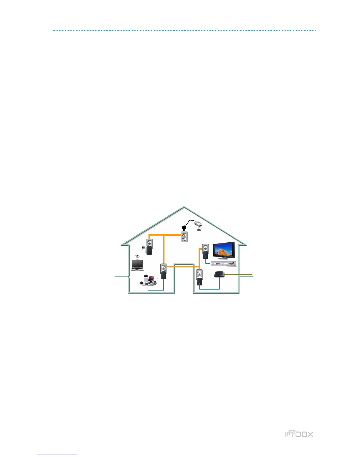
Figure 1 PLC network architecture
1.3 System Requirements
Operating system: Windows 98SE, 2000, ME, XP 32/64 bit, Vista 32/64bit and WIN7 32/64bit
CPU: Intel Pentium III or better, clock rate faster than 2.0GHz recommended
RAM: At least 128MB
Screen resolution: Any resolution
Free disk space: At least 20MB
Network interface: At least one Fast Ethernet (100 Mbps) network card and Ethernet patch cord.
ADSL
FTTH
WiFi Extender
PLC Camera
Powerline
PLC
PLC PLC
ADSL
FTTH
WiFi Extender
PLC Camera
Powerline
PLC
PLC PLC

6/24
InnboxPLC500M-UM-01-EN-020 INN-001
© The contents of this document are the property of Iskratel, Kranj, Slovenia, and may not be copied, reproduced or disclosed to a third party without written consent of the owner.
2SAFETY PRECAUTIONS
This device is intended to be used for connection to the AC powerline. For installation instructions, please refer to the
installation section of this guide. The following precautions should be taken when using this product.
Read all instructions before installing and operating this product.
Follow all warnings and instructions marked on the product.
Unplug the device from the wall outlet before cleaning. Use a damp cloth for cleaning. Do not use liquid
cleaners or aerosol cleaners.
Do not operate this product near water.
This product should never be placed near or over a radiator or heat register.
Do not use an extension cord between the device and the AC power source.
Only a qualified technician should service this product. Opening or removing covers may result in exposure to
dangerous voltage points or other risks.
Do not plug the device into a power strip or surge protector because these devices may consist of filter and
impair signal.
Avoid plugging the device right next to noisy sources such as cell phone charger, Halogen light, noisy desktop
computer, vacuum cleaner, etc. These cases result in poor transmission speed.
Unplug the device from the wall outlet and refer the product to qualified service personnel for the following
conditions:
oIf liquid has been spilled into the product
oIf the product has been exposed to rain or water
oIf the product does not operate normally when the operating instructions are followed
oIf the product exhibits a distinct change in performance
7/24
7
3GETTING TO KNOW THE ADAPTER
3.1 The Ethernet Interface
Ethernet: The Ethernet port connects to an Ethernet network cable. The other end of the cable connects to your
computer or other Ethernet-enabled network device.
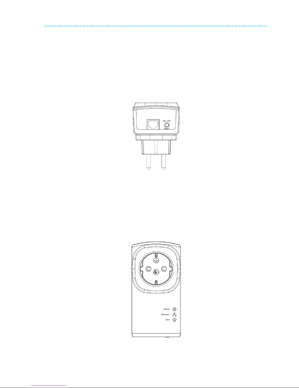
3.2 The Adapter's Buttons
The following figure shows the adapter’s buttons.
Figure 2 Side panel of the device
Security\Reset: Set the status of the device members or restore the factory default settings.
Pressing and holding the Security\Reset button for less than 3 seconds makes the adapter a member of the
existing AV Logical Network (AVLN). Pressing and holding the Button for between 10 seconds and 15 seconds
makes the adapter restore the factory default settings.
3.3 The Adapter's LEDs
All adapters’ LEDs are located on the front panel. There are 3 LEDs to indicate the adapter’s status.
Figure 3 Top view
The following table describes the LEDs on the device.

8/24
InnboxPLC500M-UM-01-EN-020 INN-001
© The contents of this document are the property of Iskratel, Kranj, Slovenia, and may not be copied, reproduced or disclosed to a third party without written consent of the owner.
LED
Behavior
Description
(Power)
Green ON
Device runs normally.
Green Blink
Device is resetting or device is in the process of password synchronization.
OFF
The PLC adapter is powered off.
(Ethernet)
Green ON
Ethernet connection has established.
Green Blink
Data is being transmitted.
OFF
No Ethernet connection.
(Data)
Green ON
The PLC adapter has connected to the powerline network.
OFF
The PLC adapter does not connect to the powerline network.
Note:
When data is being transmitted, the Data indicator keeps on but does not blink.

9/24
9
4HOW TO INSTALL THE UTILITY
Note:
Before installing the PLC utility software, make sure that there is no any other powerline utility installed on your
computer. If there is another utility installed, please uninstall it and restart your computer.
Follow the steps below to install the utility. No password or CD-Key is needed.
[R 1] Please insert the utility CD into the computer’s CD-ROM drive. Select the PLC 500AV Utility Installation
folder and then double-click the setup.exe. The page for installing the utility software is displayed.
Figure 4 Open the setup wizard
[R 2] Click Next to display the following page.
Figure 5 License agreement
[R 3] Select I Agree and click Next to display the following page.
10/24
InnboxPLC500M-UM-01-EN-020 INN-001
© The contents of this document are the property of Iskratel, Kranj, Slovenia, and may not be copied, reproduced or disclosed to a third party without written consent of the owner.
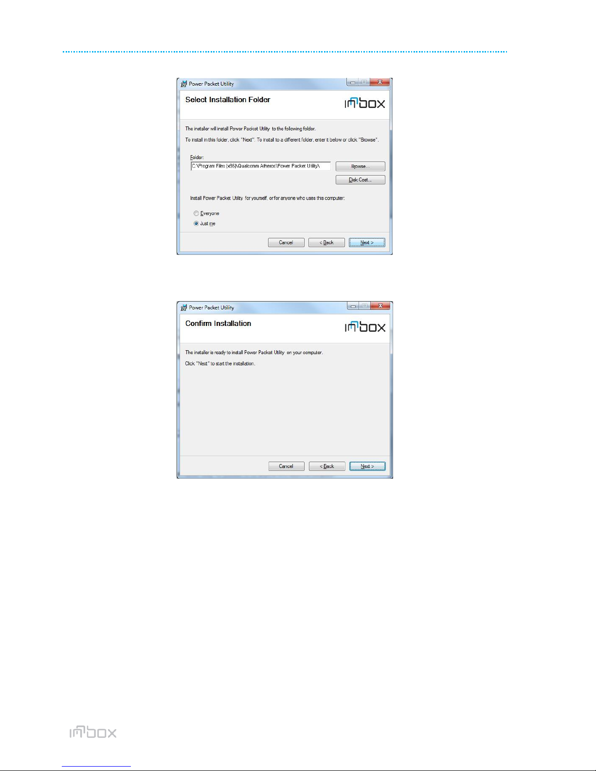
Figure 6 Selecting the folder
[R 4] Click Browse…to select the installation folder, and then click Next to continue.
Figure 7 Confirm installation
[R 5] Click Next to display the following page.
Table of contents


