Repotec RP-PE101 User manual

Quick guide for Power over Ethernet Adaptor
1. Introduction
Thank you for purchasing our Power-over-Ethernet Adapter Kit / 802.3af
Power-over-Ethernet PSE Adapter. (PSE refers to “Power Sourcing Equipment”)
Before you start installing the Power-over-Ethernet Adapter Kit / 802.3af
Power-over-Ethernet PSE Adapter, verify the following parts in the package.
1.1 Package Contents
The package contains the following:
Power-over-Ethernet Adapter Kit
One unit Power-over-Ethernet Injector, and one unit of Power-over-Ethernet
Splitter
One DC Power Adapter
A Quick Installation Guide for Power-Over-Ethernet Adapter Kit
802.3af Power-over-Ethernet PSE Adapter
One unit of 802.3af Power-over-Ethernet PSE Adapter
One DC Power Adapter
A Quick Installation Guide for Power-over-Ethernet PSE Adapter
If you do not have any of the items listed above, please contact your local distributors
or authorized resellers of the manufacturer.
1.2 Getting to Know the Power-over-Ethernet Adapter Kit /
Power-over-Ethernet PSE Adapter
Power-over-Ethernet Adapter Kit
Injector
Mixes data and power into the RJ-45 connector and then transmits power and data
over the Cat5 cable.
Splitter
Splits data and power out. It can output Ethernet data and DC 5V/1.67A or 12V/1A
power. The network device can accept the power and Ethernet data from the Splitter.
802.3af Power-over-Ethernet PSE Adapter
Mixes data and power into the RJ-45 connector and then transmits power and data to
the Terminal. The module must be use a chip that is compliant 802.3af solution’s
controller.

2. Installation
This chapter describes the function of the Power-over-Ethernet Adapter Kit /
Power-over-Ethernet PSE Adapter and shows how to install it on your network. Basic
knowledge of networking is assumed. Read this chapter before you proceed.
2.1 View and LEDs
The following figures show the views of Injector and Splitter / Power-over-Ethernet
PSE Adapter. And Table explains the objects of the device.
Figure 2.1 Injector / 802.3af Power-over-Ethernet PSE Adapter
Figure 2.2 Splitter
Figure 2.3 Power LED

Table 2.1
Object Description
PWR Injector / Power-over-Ethernet PSE Adapter
Power and Data Out Port Lights green to indicate that the power has been supplied to the device
DC Jack Connects the RJ-45 port of Splitter through Cat 5 Ethernet cable
Cat 5 Ethernet Cable Connects to the power adapter for receiving power
PWR Connects to other network devices
Power and Data In Port Splitter
Cat 5 Ethernet Cable Lights green to indicate that the power has been supplied to the device
Power Cable Connects the RJ-45 port of Injector through Cat 5 Ethernet cable
Voltage Selector Connects to other network devices
Connects to other DC jack on the network device
Used to select DC 5V/1.67A or 12V/1A power

2.2 Connecting the Power-over-Ethernet Adapter Kit /
Power-over-Ethernet PSE Adapter
The Power-over-Ethernet Adapter Kit / Power-over-Ethernet PSE Adapter do not
need software configuration. To install it, simply complete the following steps. Figure
2.4 shows how the Power-over-Ethernet Adapter Kit is connected to your wireless
network; Figure 2.5 shows how the Power-over-Ethernet PSE Adapter is connected to
your wireless network.
Step 1 Select a location for your Power-over-Ethernet Adapter Kit /
Power-over-Ethernet PSE Adapter. Put it on a sturdy desktop. Keep enough
ventilation space between the device and the surrounding objects.
Step 2 Connect the DC power adapter to the Injector / Power-over-Ethernet PSE
Adapter and plug the DC power adapter into a power socket.
Step 3 Connect the Injector’s / Power-over-Ethernet’s built RJ-45 Cat 5 Ethernet
cable to your network.
Step 4 Connect the RJ-45 Cat 5 Ethernet cable to the Injector’s / Power-over-Ethernet
PSE Adapter’s Power & Data Out port.
For the Adapter Kit, connect the other end of the Ethernet cable to the Splitter’s Power
& Data In port.
For the Power-over-Ethernet PSE Adapter, connect the other end of the Ethernet
cable to the other networking device. Then you have finished the connecting of
Power-over-Ethernet PSE Adapter by Step 1 to 4.
Step 5 Connect the Splitter’s RJ-45 Cat 5 Ethernet cable to your networking device.
Finally, connect the Splitter’s power cable to the other power port on networking
device.

Figure 2.4
Figure 2.5

3. Specifications
3.1 Cable Specifications
Table 3.1 lists the cables you can use and their specifications.
Caution: Please do not use telephone cables. Telephone cables do not support
Ethernet or Fast Ethernet
Table 3.1 Straight-Through and Crossed-Over Cable Specifications
Ethernet Type Cable Requirements Maximum Length
10BASE-T Category 3 or better, UTP or STP 328 ft (100M)
100BASE-TX Category 5 or better, UTP or STP 328 ft (100M)
Twisted-pair cabling comes in various grades, or categories. Category 5 is required for
Fast Ethernet, and is also the most reliable and most commonly used category. You
can buy UTP Category 5 (Unshielded Twisted Pair) Ethernet cabling in precrimped
lengths, or you can crimp your own. Crimping your own can result in faulty
connections if the
RJ-45 tips are not attached properly. Precrimped Category 5 cabling is available at
most computer retail stores.
The most reliable and commonly used type of Category 5 cabling used is UTP, or
"unshielded twisted pair." STP, or "shielded twisted pair" wiring is only necessary for
network environments exposed to excessive amounts of electromagnetic interference,
or EMI. These environments include areas with high sources of electrical power, air
conditioning, generators, and radio signals. STP is also used for wiring outdoors.
There are two types of the wiring: Straight-Through Cables and Crossover Cables.
Category 5 UTP/STP cable has eight wires inside the sheath. The wires form four
pairs. Straight-Through Cables has same pinouts at both ends while Crossover
Cables has a different pin arrangement at each end.
In a straight-through cable, wires 1,2,3,4,5,6,7 and 8 at one end of the cable are still
wires 1~8 at the other end. In a crossover cable, the wires of 1,2,3,6 are reversed so
that wire 1 become 3 at the other end of the cable, 2 becomes 6, and so forth.
To determine which wire is wire 1, hold the RJ-45 cable tip with the spring clip facing
towards the ground and the end pointing away from you. The copper wires exposed
upwards to your view. The first wire on the far left is wire 1. You can also refer to the
illustrations and charts of the internal wiring on the following page.
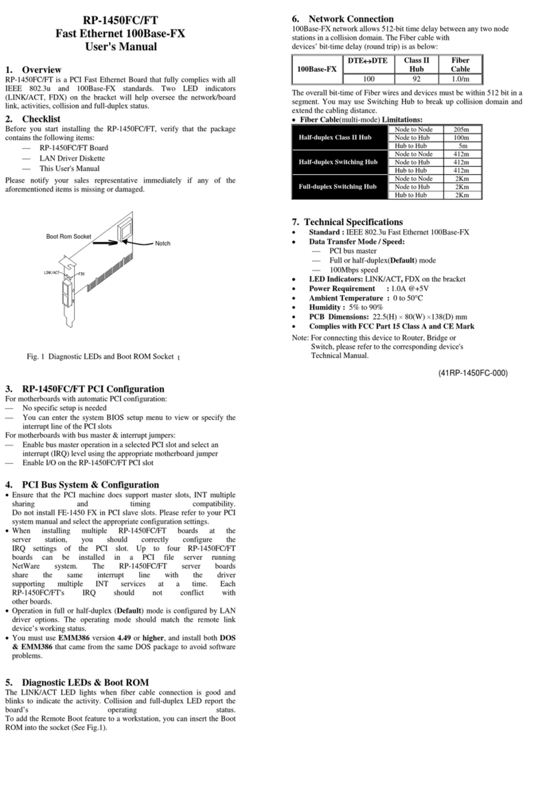
Figure 3.1 Straight-Through Cabling
Figure 3.2 Cross-Over Cabling

3.2 Technical Specifications
Standards IEEE 802.3, IEEE 802.3u, IEEE 802.3x,
IEEE 802.3af (802.3af Power-over-Ethernet PSE Adapter only)
Protocol CSMA/CD
Ports 1 * 10/100Mbps RJ-45 port (per unit)
Connector RJ-45
Speed 10/100Mbps at half/full duplex
Cable Type UTP/STP Category 5 or better
LED Power
3.3 Environmental Information
Dimensions (WxHxD) Adapter Kit: 89 x 47 x 30 (mm)
PSE Adapter: 89 x 47 x 30 (mm)
Unit Weight Injector: 64g Splitter: 87g
PSE Adapter: 64g
Operating
Temperature 0°C to 40°C (32°F to 122°F)
Storage Temperature -55°C to 105°C (-67°F to 221°F)
Operating Humidity 10% to 90% relative humidity, non-condensing
Storage Humidity 20% to 95% relative humidity, non-condensing
Power DC 48V
3.4 Standard Conformance
EMC Certification FCC Class B, CE
Table of contents
Other Repotec Adapter manuals

Repotec
Repotec UBM302G User manual

Repotec
Repotec RP-3200R User manual

Repotec
Repotec RP-WU5111A User manual

Repotec
Repotec RP-WU5204 User manual

Repotec
Repotec RP-1200ES+ User manual

Repotec
Repotec RP_3000EX_ML User manual

Repotec
Repotec RP-UB215B User manual

Repotec
Repotec RP-1450FC User manual

Repotec
Repotec RP-3200EX User manual