InnoMedia InfoView IV 3000 User manual

IV 3000 / IV 2000
Version 1.30

Congratulations on your purchase of the InnoMedia InfoView.
InfoView brings you the Video Phone, the next generation of communication
where you can enjoy enriching communication of voice and video. Using
your TV as the screen while transmitting voice and images through a phone
line, InfoView optimizes the use of readily available consumer electronics
products.
In addition, the InfoView unit is also equipped with many practical features
such as Auto Answer, High Quality TV Output, VCR Recording Capability,
Software Upgrade and more.
Full understanding of what this product offers begins with reading this
operating manual. This operating manual includes a Quick Start Chapter for
you to set up your unit quickly and effectively.
Copyright 1999 InnoMedia Inc.
All rights reserved.
* Specifications subject to change without notice
I
IV 3000 / IV 2000
Version 1.30

II
COPYRIGHT
Copyright 1999 InnoMedia Inc.
Published by InnoMedia, who reserves the right to make improvements in the products
described in this operating manual as well as to revise this publication at any time and
without notice to any person of such revision or change.
All rights reserved No part of this publication may be reproduced, transcribed, stored
in any electronic retrieval system, translated into any language or computer language,
or be transmitted in any form whatsoever without the prior written consent of the
published. For additional information contact:
InnoMedia Inc.
90 Rio Robles, Suite 100
San Jose, CA 95134
Tel: (408) 432-5400 Fax: (408) 432-5404
InnoMedia Pte Ltd.
10 Science Park Road, #03-04/05
The Alpha, Singapore 117681
Tel: (65) 872-0828 Fax: (65) 872-0900
InnoMedia Technology Inc.
3F, No 3, Industrial East Road. IX,
Hsinchu Science Based Industrial Park,
Hsinchu, Taiwan
Tel: (886) 3-564-1299 Fax: (886) 3-564-1589
Innomedia Website: http://www.innomedia.com
TRADEMARKS
All brand and product names are trademarks or registered trademarks of their
respective holders
NOTICE
All titles, versions, trademarks, claims of compatibility, etc., of hardware and software
products mentioned herein are the sole property and responsibility of the respective
vendors InnoMedia makes no endorsement of any particular product for any purpose,
nor claims responsibility for its operation and accuracy.
UPDATES
Updates to the products and the manual are obtainable at participating InnoMedia
dealers and distributors or through Innomedia website.

III
1. Quick Start Page 1
2. Introduction 4
3. Knowing Your InfoView 6
3.1 InfoView Package Content List
3.2 Features
3.3 InfoView Layout
4. Installing Your InfoView 8
5. Learning the On-Screen Menu 10
6. Making Your Video Call via InfoView 33
7. Application & Benefits of InfoView 34
8. Technical Specifications 36
9. Troubleshooting and Usage Tips 38
10. Important Safety Instructions 42
11. Maintenance & Care 43
12. FCC Registration Information 44
Contents

Chapter1Quick Start Page
1
Step A: Set-Up Procedures for InfoView
1. First, disconnect your phone cable from the wall phone connector, and connect it
to the PHONE connector at the back of the InfoView. If your phone cable is not
long enough, please use the phone cable provided for the connection. There are
two phone cables with different lengths in your InfoView package
2. Next, insert the second phone cable to the LINE connector at the back of
InfoView, and connect the other end to the wall phone jack.
3. Plug in the color-coded Audio/Video cable to the respective AUDIO/VIDEO-OUT
connectors at the back of InfoView. Connect the other ends of the cable to the
AUDIO/VIDEO-IN connectors at the back of your TV. Please refer to the above
drawing for proper location of the related connectors.
This chapter explains how to set up your InfoView. After you follow the instructions in
this chapter, you will be ready to make your video call.
Audio In
Audio Out
Video Out
DC 12
Power Input
Video In To Phone
To Wall Socket

2
4. Plug in the power adapter to the wall power socket. 5DO NOT switch ON the
power adapter at this point
5. Connect the pin of your power adapter to the small power socket located at the
back of InfoView, labeled POWER DC 12V.
6. You have successfully set up your InfoView.
7. Switch ON the power adapter and press the power switch 6at the front of your
InfoView to power ON InfoView
8. A good location to place your InfoView is on top of your TV or beside it
[Optional] Step B: Set-Up Procedures for InfoView WITH EXTERNAL CAMERA
(Camcorder)
1. First, disconnect your phone cable from the wall phone connector, and connect it
to the PHONE connector at the back of the InfoView. If your phone cable is not
long enough, please use the phone cable provided for the connection. There are
two phone cables with different lengths in your InfoView package.
2. Next, insert the second phone cable to the LINE connector at the back of
InfoView, and connect the other end to the wall phone jack.
3. Plug in the provided color-coded Audio/Video cable to the respective
AUDIO/VIDEO-OUT connectors at the back of InfoView. Connect the other ends
of the cable to the AUDIO/VIDEO-IN connectors at the back of your TV. Please
refer to the above drawing for detailed location of different connectors.
Audio In
Audio Out
Video Out
DC 12
Power Input
Video In To Phone
To Wall Socket

3
4. Plug in AUDIO/VIDEO cable that comes with your camcorder to the
AUDIO/VIDEO-IN connectors of the InfoView and connect the other end to your
Camcorder’s AUDIO/VIDEO-OUT connectors.
5. Plug in the power adapter to the wall power socket. 5 DO NOT switch ON the
power adapter at this point.
6. Connect the other end of your power adapter to the small power socket located
at the back of InfoView, labeled POWER DC 12V.
7. You have successfully set up your InfoView.
8. Switch ON the power adapter and press the power switch 6at the front of your
InfoView to power ON InfoView.
Step C: Visual Communication via InfoView
1. Make sure step A or step B above is completed successfully.
2. Turn ON the TV and set it in VIDEO mode. Call the other party as you normally
would.
3. After the phone connection is established, you may choose to start your visual
conversation at any point in time. Make sure the other party has also set up the
unit properly. Press 7for on-screen menu.
4. Press 7-2on your phone’s key pad to start video call. Either party may do so to
start an InfoView call. If the remote party is not using InfoView, please try the 3
Call function or 4Answer if you are making call to or receiving call from other
H.324 compliant system
☞For the InfoView with a built-in camera, you may adjust the camera to capture the
desired view using the Pan, Tilt & Zoom features. For the InfoView using external
camera (camcorder), you should adjust the camcorder accordingly to capture the
desired view.
You are ready for the visual communication.
Enjoy the new, enriching experience.
123
ABC DEF
456
JKL MNOGHI
789
TUV WXYZPQRS
*
0#

4
Chapter 2Introduction
InfoView - Extraordinary Visual Communication Through Ordinary TV
A Picture Is Worth A Thousand Words. Complete communication demands more than
words, hence visual communication is a preferred communication method for the
future, available to you now.
InnoMedia offers the InfoView, a TV-based video phone system that turns your TV into
a Video Phone using your regular phone line. InfoView will optimize the usage of your
phone Iine by transmitting both voice and video in one single line, hence you can talk
to the other party and see him/her at the same time, WITHOUT incurring additional
cost.
What does visual communication mean?
Visual communication allows better communication by combining both voice and
images, and the end results will translate into tremendous benefits for the users.
a. Cost Reduction & Time Savings
When you can discuss and collaborate with your associates or your foreign
suppliers via InfoView, you will save on unnecessary overseas trips. Therefore,
you can reduce your operating costs as well as the time spent on traveling.
Furthermore, you can keep in touch with your associates or counterparts
better since you can have face-to-face discussion more often, even thousand
of miles apart.

5
InfoView is a cost savings device which complements your day-to-day business
operation.
b. Relationship building
As friends and family move to other cities or countries, you can still keep the
relationship intact by having close communication with them. By using
InfoView, you can see your loved ones at anytime without hesitation since the
images come free whenever you make a call to them. InfoView is a valuable
gift which your friends and family will appreciate greatly.

6
Chapter 3Knowing Your InfoView
3.1 InfoView Package Content List
Thank you for choosing the InfoView, we hope that it will bring you enriching visual
communication Your InfoView packaging includes the following items:
1InfoView unit (Unless specifically
indicated, all InfoView units will
come with the camera unit)
2standard
telephone cables 1pair of colour-coded
audio/video cable 1power adapter
(DC 12V, 1.5A)
1InfoView
Operating Manual
3.2 Features
Your InfoView comes with the following features which complement your visual
communication:
a. High Quality TV Output
b. Auto Answer
c. Caller ID (Available when Caller ID service is subscribed)
d. On-Screen Graphical Menu
e. High Quality Digital Zoom Camera (Optional)
f. Privacy mode with Password protection
g. Customized modem settings
h. Software Upgrade Capability
i. Snap Shot, PowerSave ON/OFF
j. External Camera Input for Camcorders
k. Record on-screen session through your VCR
m. Local & Remote Zoom, Pan and Tilt Features (Only limited to local & remote
InfoView with built-in camera)

7
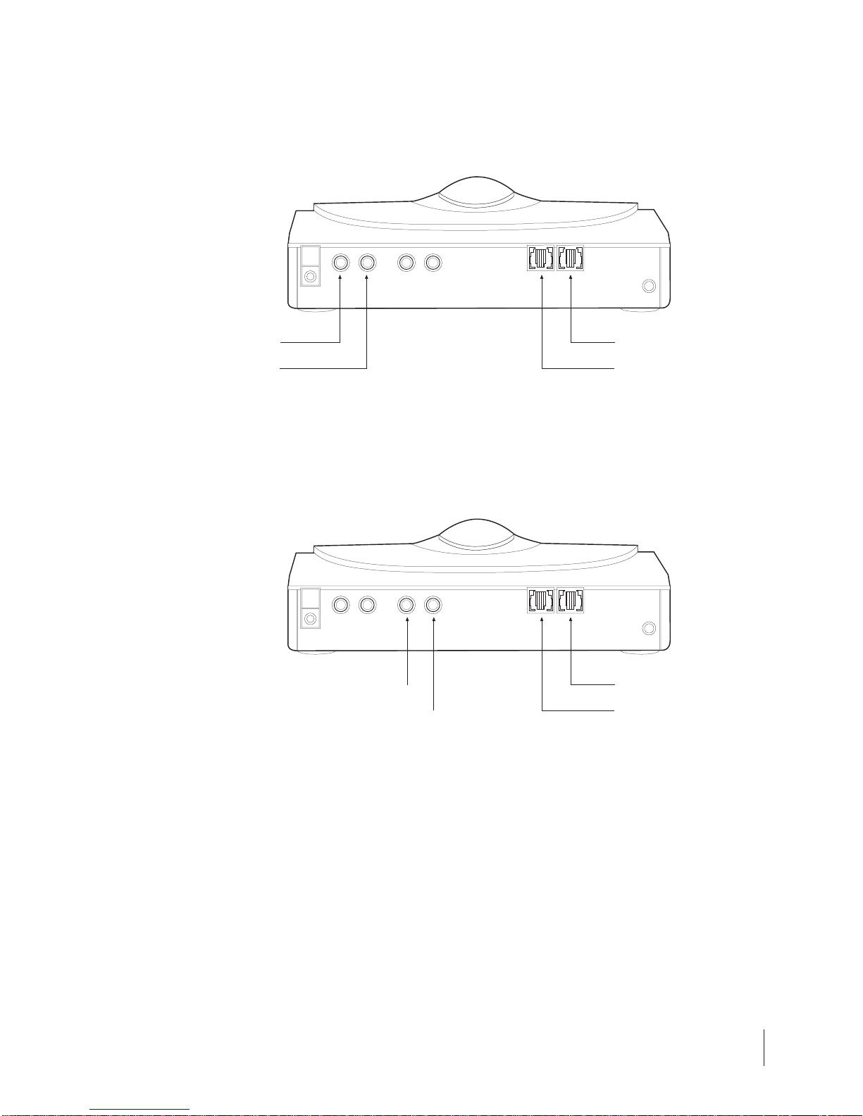
No. Item Description
1 Camera A high quality auto-focus camera len is provided.
InfoView also has a model that comes without
buiIt-in camera which caters to users with their own
camcorders instead
2 Power Switch 6Pressing this button will turn InfoView ON
Pressing the button again will turn InfoView OFF
3 Power LED [Green] The LED will be green when the power adapter is
switched ON. The LED will become brighter when
the Infoview power switch is ON.
4 Status LED [Red] LED will be red when InfoView is operational
5 DC Power Input Socket DC 12 V 1.5A power input for InfoView
6 Video Out An output connector for video / image signal
7 Audio Out An output connector for audio / voice signal
8 Video In An input connector for video / image signal
9 Audio In An input connector for audio / voice signal
10 RJ 11 socket for Line RJ 11 socket for connection to the wall phone jack
11 RJ 11 socket for Phone RJ 11 socket for connect on to the phone unit.
12 Reset Button Pressing the internal pin and the power switch
simultaneously will reset the InfoView
3.3 InfoView Layout
Front View:
Back View:
1
65 7 8 9 10 11 12
234

8
Chapter 4Installing Your InfoView
Hardware Installation
This section describes the hardware installation process for your InfoView.
Installing InfoView
1. First, disconnect your phone cable from the wall RJ-11 phone jack. Connect it to
the connector labeled “PHONE” at the back of your InfoView unit. If your phone
line is not long enough, please use the phone cable provided for the connection.
2. Next, take out the second phone cable, connect one end to the wall RJ-11 phone
jack, and the other end to the connector labeled “LINE” at the back of your
InfoView unit.
Line Phone
9
3. If you have bought an InfoView unit with a built-in camera, connect one end of
the color-coded Audio/Video cable to the AUDIO/VIDEO OUT connectors of your
InfoView unit, and the other end to the AUDIO/VIDEO IN connectors at the
back of your TV.
4. (Optional) If you plan to use your camcorder as the external camera instead,
please connect an additional pair of Audio/Video cable to the AUDIO/VIDEO-IN
connectors at the back of your InfoView unit, and the other end to your
camcorder’s AUDIO/VIDEO-OUT connectors.
5. Connect your power adapter to your wall power socket, and connect the
adapter’s pin to the power socket labeled POWER DC 12V at the back of your
InfoView. 5DO NOT switch on the power adapter at this point.
6. Check all the connections mentioned above. If everything is connected correctly,
you can switch ON the power adapter and press 6on your InfoView to turn ON
the unit.
7. You have successfully installed your InfoView.
8. A good location to place your InfoView unit is either on top of your TV or
beside it.
Audio
In
Video
In
Video Out
Audio Out
Phone
Line
Phone
Line
10
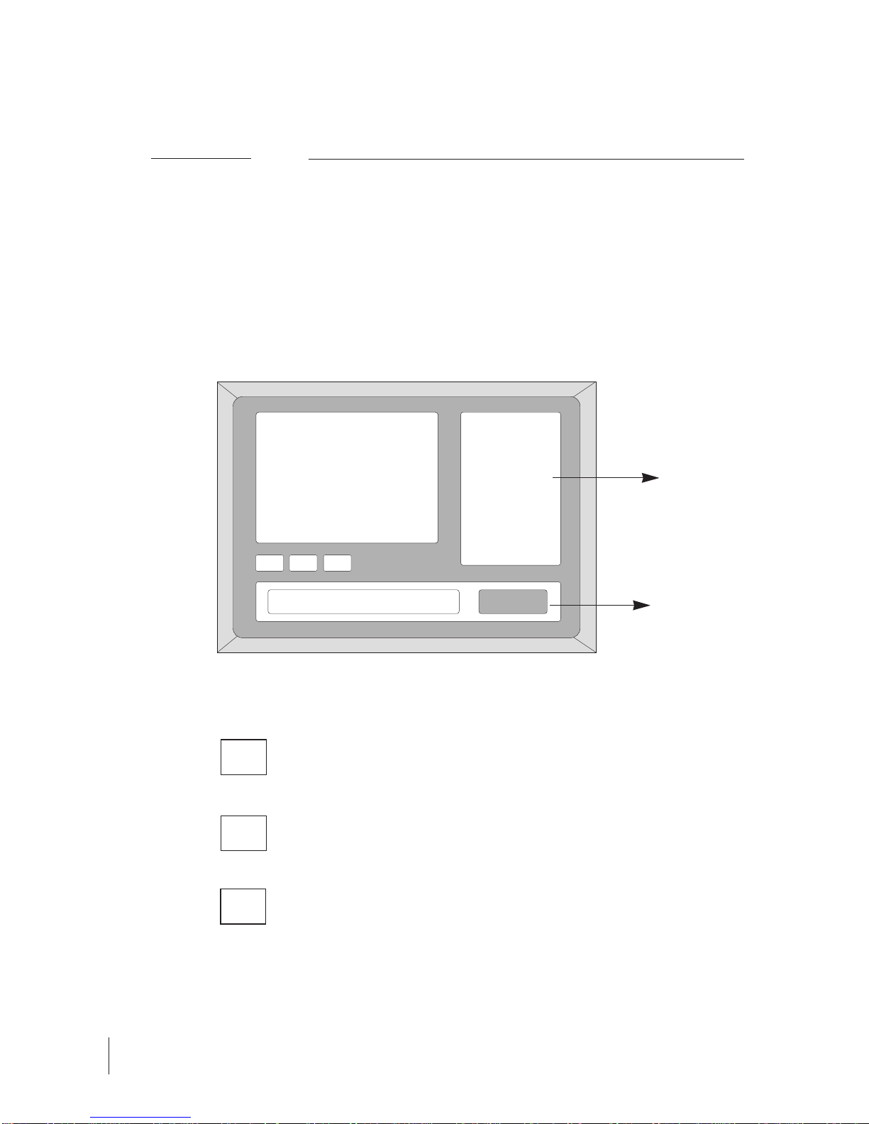
Chapter 5Learning the On-Screen Menu
I. InfoView On-Screen Menu
When you first switch on the TV and turn on the InfoView. You should see the
following on your TV screen.
12:08:18
Message Prompt Box
If system is set to Auto Answer, ANS is in green color.
Otherwise, it will remain as light brown.
When you pick up the phone, LINE will turn green.
Otherwise, it will remain light brown.
When InfoView has system error, SYS will turn red.
Otherwise, it will remain as green
LOCAL VIEW ON-SCREEN
MENU
ANS LINE SYS
Press “#” on
phone key pad
to start menu
Clock starts
running once
InfoView is
switched ON.
ANS
LINE
SYS

11
You may control your InfoView using this menu prior to your video phone
conversation, the menu will change once you have connected for your video phone
conversation. Please refer to the table below for brief references on the On-Screen
Menu prior to video phone conversation.
5.1 Making & Receiving Video Call
InfoView works seamlessly with your current phone, you can have your voice
conversation on the phone and activate the InfoView anytime at your
convenience, provided the other party has a video phone system set up as well.
We support the ITU-H..324 standard for video-conferencing. Therefore, InfoView
allows you to specify the type of system you want to communicate with prior to
your phone connection.
On Screen Menu Sub-menu Main function
• Main Menu To provide easy one-step video phone connection
• Settings To configure the InfoView according to usage
preferences
• Camera To control the built-in camera
• TV Screen To specify the TV type
• Security To switch into privacy mode with higher security
• System To access features which concern the InfoView
system
• Modem To fine-tune the modem for different country
settings
• Upgrade To access the easy dial-up upgrade
☞Press # to access the on-screen menu. The menu will disappear into the
background within a few seconds if you did not make any selection. When you
press # again, the menu will reappear and it will be on the page when you last
exited.
☞If you subscribe to Caller ID service, you will see phone number of the incoming
call on the TV screen through lnfoView Caller ID capability.
☞Your InfoView comes with an on-screen menu which have both text and numbers
to help you configure the system to your preference.
☞To use each of the function, simply press the number indicated on the screen that
represents the individual function.
☞Please turn on your TV and set it in video mode so that it can receive the
incoming signal from InfoView.
123
ABC DEF
456
JKL MNOGHI
789
TUV WXYZPQRS
*
0#

12
Main Menu
[Press 7
to access main menu]
(4) Settings
(5) About
(3) Answer
(2) Call
(I) InfoView
To make a video call to remote InfoView
1. Turn on your TV and set it in the correct channel that receives external video input
from InfoView.
2. Switch on InfoView and press 7to access menu. Within seconds you should see
your self-view and the on-screen menu on the TV. The Main Menu is located on
your right.
3. Call the other party as you normally would.
4. After the remote party picks up the phone, press (1) to START a video call to a
remote user with InfoView.
5. Please wait for connection.
To make a video call to similar H.324 video phone system
1. On the Main Menu, please press (2) to START a video call with another H.324
video phone system.
2. Please wait for connection.
To receive a video call from similar H.324 video phone system
1. On the Main Menu, please press (3) to ACCEPT the video call from another H.324
video phone system.
2. Please wait for connection.
To check InfoView system information
1. On the Main Menu, press (5) to view the InfoView system information.
2. You will see InfoView’s version number, modem information as well as the Privacy
Mode password information on screen. [IF this is the first time you access this
section, your password will be 0000, you may proceed to the Privacy Mode via
Security Feature section for more information on password setting]
IF you happen to activate a video call accidentally, you may hang up
the phone to cancel the function. Your InfoView will restart and go
back to the original condition.
Tips

13
(4)SETTINGS SETTINGS (1)Camera
(1) Camera CAMERA (4), (6)
Pan Camera
(2),(8)
Tilt Camera
(1), (7)
Zoom Camera
Controlling the InfoView built-in camera
1. On the Main Menu, press (4) to access the Settings Menu.
2. Within the Settings Menu, press (1) to get into the Camera sub-menu.
To pan local camera
1. On the Settings Menu, press (1) to access the Camera sub-menu.
2. Press (4) to pan the camera LEFT
3. Press (6) to pan the camera RIGHT
4. Once you have chosen a preferred position, simply press (5) to exit.
To tilt local camera
1. On the Settings Menu, press (1) to access the Camera sub-menu.
2. Press (2) to tilt the camera UPWARD
3. Press (8) to tilt the camera DOWNWARD
4. Once you have chosen a preferred position, simply press (5) to exit.
To zoom with the local camera
1. On the Settings Menu, press (1) to access the Camera sub-menu.
2. Press (1) to ZOOM IN
3. Press (7) to ZOOM OUT
4. Once you have chosen a preferred position, simply press (5) to exit.
5.2 Specifying the Settings of your InfoView
MAIN MENU

14
Specifying the TV Type
•InfoView can support both NTSC and PAL signal.
•Users need to specify the TV type for the InfoView system.
To specify TV Type
1. On the Settings Menu, press (2) to access the TV Screen sub-menu.
2. Press (3) on TYPE to toggle between NTSC and PAL.
•IF your TV is NTSC, when you toggle and see NTSC on screen Press (5) to
exit. You have made your selection.
•IF your TV is PAL, when you toggle and see PAL on screen. Press (5) to exit.
You have made your selection.
•IF your TV is multi-system, press (5) to exit. You do not need to do anything.
(2) TV Screen
(3)Type
(5) Back
SETTINGS
TV SCREEN

15
• Every InfoView will come with a built-in camera, unless specified otherwise.
• However, users can always connect an external camera (camcorder) to the
Audio/Video INPUT jacks at the back of the InfoView. As a result, users can now
use the external camera for viewing at their preferences.
• Once decided to switch to external camera, please update the camera type and
source for the InfoView system.
To specify Camera Type
1. On the Settings Menu, press (1) to access the Camera sub-menu.
2. Press (9) on CONFIG to proceed to the camera submenu
• To specify the camera type (NTCS/PAL), press (1) on TYPE and toggle for the
correct camera type.
• To specify the camera source (Internal built-in/External camcorder), press (2)
on SOURCE and toggle for the correct camera source.
3. Upon completion, press (5) to exit.
(1) Camera
1. Type
2. Source
5. Back
(9) Config
(9) Config
SETTINGS
CAMERA
Specifying the Camera Type

16
• InfoView has built-in security feature which allows you to activate privacy mode so
that the remote party will not be able to see you. The feature enables the
capability of blocking the local pictures so that the remote party cannot view it.
• With the InfoView security feature, users can have their video phone conversation
at their discretion with full control at their ends.
To provide password for Privacy Mode
1. Under the Settings Menu, press (3) to go to the Security sub-menu.
2. When you activate the privacy mode, remote party will need to enter a special
password (preset by you) in order to regain the video mode.
3. Press (2) to set password
•Key in the numeric password by typing the corresponding number on
your phone key pad. For instance, if your password is 1234, simply press
1234 on your phone key pad.
•Press (*) to reset the password if you want to key in new password.
•Press (#) to exit the screen and get back to the previous screen.
4. Upon completion, press (5) to exit.
To activate Privacy Mode
1. Under the Settings Menu, press (3) to go to the Security sub-menu.
2. Press (1) to activate Privacy Mode.
3. You should see your Local View blackened off. Therefore, the remote side will
not be able to see you as well.
Privacy Mode through lnfoView Security Feature
(3) Security
(1) Privacy
(2) Password
(5) Back
SETTINGS
SECURITY
This manual suits for next models
1
Table of contents
Popular Conference System manuals by other brands


Clear One
Clear One MAX IP Response Point Administrator's guide

Clear One
Clear One Converge Pro 880 Installation & operation manual

Chatter Box
Chatter Box BiT-3 manual

Clear One
Clear One Converge Pro manual

Smart Technologies
Smart Technologies SMART Room System manual

Clear One
Clear One Converge Pro TH20 Installation and operation manual