InnoSenT SMT mountable Series User manual
Experience and Reliability in Radar Technology
disclosed by the recipient to third parties without prior consent of InnoSenT in writing.
Movement
Velocity
Direction
Presence
Distance
Angle
User Manual SMR-314/334
Version 2.2 - 03.08.2020
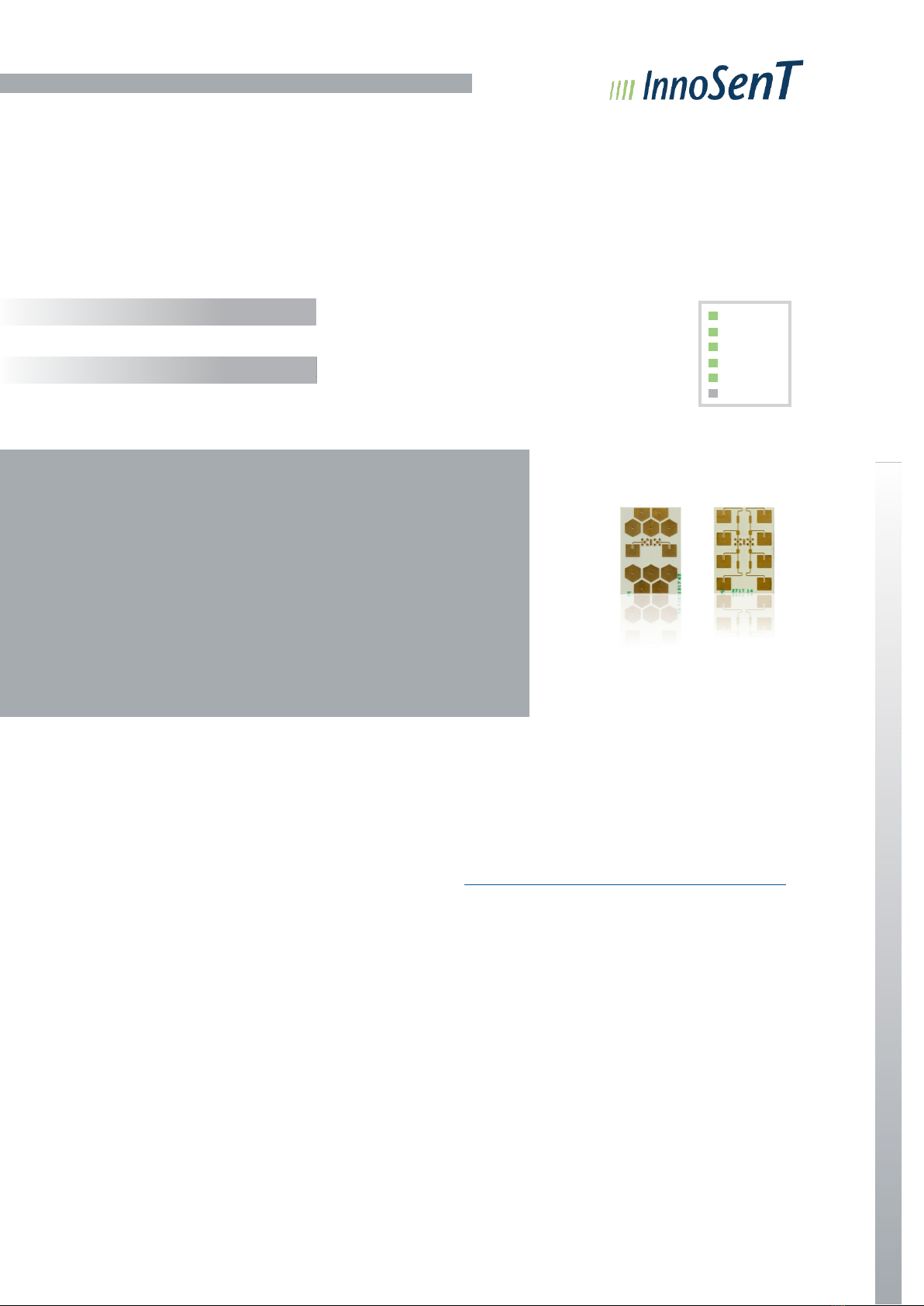
SMT mountable K-Band VCO Sensor
•Industrial Applications
•Security Applications
DESCRIPTION
K-Band based VCO Sensor. The ultra small device
will be delivered directly on tape for mounting
within a standard SMT. Due to the VCO capability
the sensor is also suitable for application whereby
frequency modulation is necessary (e.g. distance
measurement).
ETSI / FCC
All SMR modules are compliant to ETSI 300 440.
ADDITIONAL INFORMATION
InnoSenT Standard Product. Changes will not be
notified as long as there is no influence on form, fit
and within this data sheet specified function of the
product.
CERTIFICATES
InnoSenT GmbH has established and applies a quality
system for: development, production and sales of
radar sensors for industrial and automotive sensors.
https://www.innosent.de/en/company/certifications/
RoHS-INFO
This product is compliant to the restriction of
hazardous substances (RoHS - European Union
directive 2011/65/EU).
CONFIDENTIAL AND PROPRIETARY
The information contained in this document shall remain the sole and exclusive property of InnoSenT GmbH and shall not be
FEATURES:
» VCO Transceiver working in the 24GHz - ISM - Band
» Detection of direction and velocity as well as distance of moving
and stationary objects
» Integrated Prescaler for easy frequency control
» Integrated Low Noise Amplifier
» Mounting by standard SMT-Process (delivery on Tape & Reel)
» Extended temperature range from -40°C up to +85°C
» Very small outline dimensions
» Available with different antenna patterns by same interface
APPLICATIONS
PRODUCT FAMILY
Page
User Manual SMR-314 / 334
Version 2.2

Experience and Reliability in Radar Technology
disclosed by the recipient to third parties without prior consent of InnoSenT in writing.
PARAMETERS
PARAMETER CONDITIONS SYMBOL MIN TYP MAX UNITS
Radar
VCO frequency range
f
VCO
24.050
24.250 GHz
Tuning voltage to cover VCO frequency range
V
tune
0.7
2.5 V
VCO tuning sensitivity within VCO frequency range
K
VCO
720 2000 MHz/V
output power (EIRP)
P
out
20 dBm
IF output DC-Offset
IF1/2_DC-offset 1.4 1.8 2.2 V
IF-Bandwidth (-3dB)
B0
1M Hz
signal level
(RCS = 0.5m² @ 5m)
SMR - 314
IF
1/2 - SMR-314
60
250 µVrms
SMR - 334
IF
1/2 - SMR-334
120
360 µVrms
noise level 100Hz...1kHz
N
1/2
20 µVrms
quadrat. phase imbalance
εp-25
25 °
overall gain
(conversion gain + antenna
gain)
SMR - 314
G
OA - SMR-314
24
dB
SMR - 334
G
OA - SMR-334
29
Power supply
supply voltage
VCC 3.2 3.3 3.4 V
supply current
ICC
47 57 mA
Frequency Divider
Prescaler division ratio VCC_PTAT = 0 V,
D
DIV
16
VCC_PTAT = 3.3 V
D
DIV
8192
Prescaler output voltage
Peak to peak voltage
Terminated with
50Ω DDIV=8192
V
DIV
60
120
260
mV
Prescaler supply voltage
V
CC_DIV
3.2 3.3 3.4 V
Prescaler supply current
I
CC_DIV
19
mA
Environment
operating temperature
TOP -40
+85 °C
storage temperature
T
STG
-40
+85 °C
Mechanical Outlines
outline dimensions
compare to schematic on page 4
height
length
width
3.1
21.4
15.0
mm
CONFIDENTIAL AND PROPRIETARY
The information contained in this document shall remain the sole and exclusive property of InnoSenT GmbH and shall not be
Page
User Manual SMR-314 / 334
Version 2.2

Experience and Reliability in Radar Technology
disclosed by the recipient to third parties without prior consent of InnoSenT in writing.
-
90°
-50
-
40
-
30
-20
-45°
-10
45°
0°
-
90°
-50
-
40
-
30
-20
-45°
-10
45°
0°
ANTENNA PATTERN
System Pattern SMR-314:
-90° -90°
system pattern (-10dB) azimuth system_az
121
°
elevation system_el
111
°
System Pattern SMR-334:
-90° -90°
system pattern (-10dB) azimuth system_az
43
°
elevation system_el
116
°
CONFIDENTIAL AND PROPRIETARY
The information contained in this document shall remain the sole and exclusive property of InnoSenT GmbH and shall not be
-
90°
-50
-
40
-
30
-20
-45°
-10
45°
0°
-
90°
-50
-
40
-
30
-20
-45°
-10
45°
0°
Page
User Manual SMR-314 / 334
Version 2.2

Experience and Reliability in Radar Technology
disclosed by the recipient to third parties without prior consent of InnoSenT in writing.
VALUES DESCRIPTION DIMENSIONS
Ahole width 1.0 (±0.1)mm
BSMT Pad depth 0.6 (+0 -0.1)mm
CSMT Pad width 1.5 (±0.05)mm
DPin Pitch 2.0 (±0.05)mm
Ehole depth 0.2 (±0.1)mm
Fdistance from center of pin 1 to board edge
2.25 (±0.25)mm
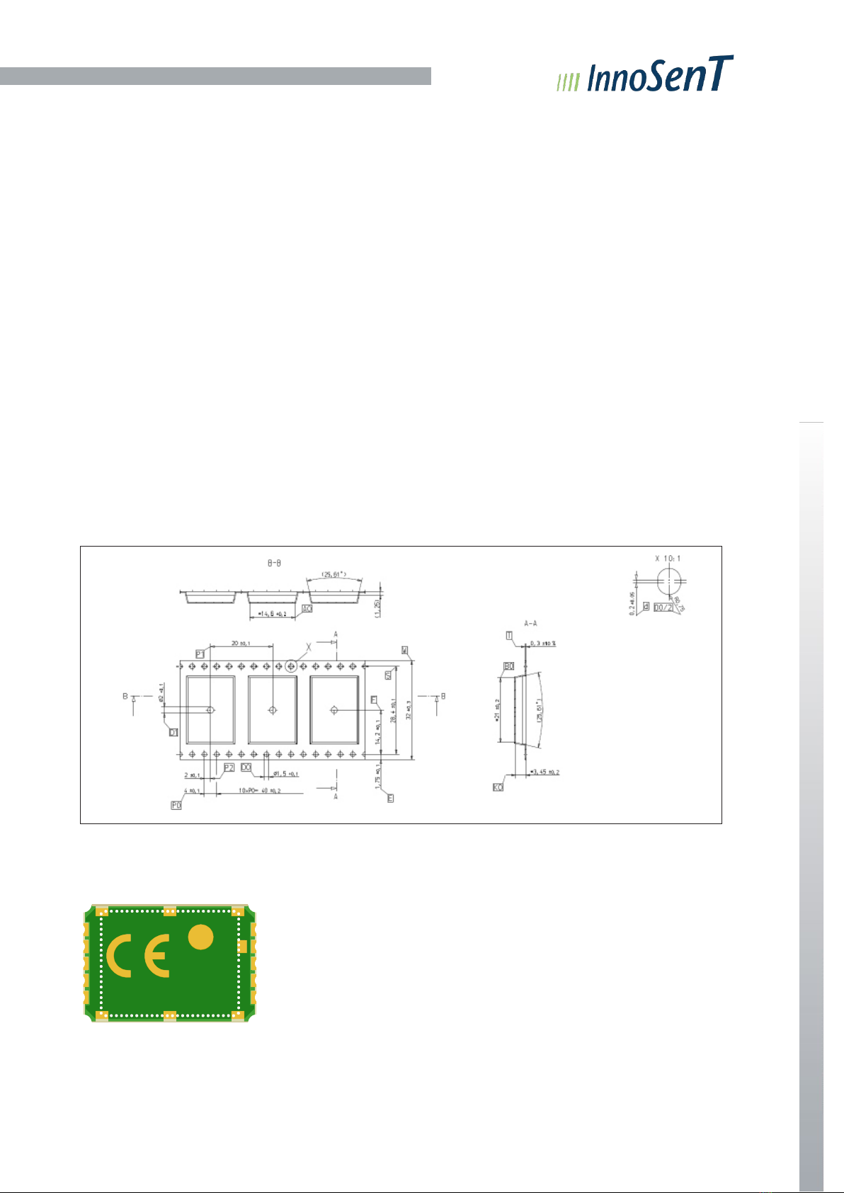
OUTLINE DIMENSIONS
INTERFACE
The sensor provides solder pads for SMT mounting.
PIN # DESCRIPTION IN/OUT COMMENT
1
V
CC_DIV
input supply voltage divider
2div_out output divider output
3IF1 output signal I(nphase)
4IF2 output signal Q(adrature)
5enable* input TX output power enable (active high)
6GND input analog ground
7VCC input supply voltage
8
V
CC_PTAT
input divider ratio setting (3.3V = 8192)
9
V
tune
input tuning voltage (0.7...2.5V)
10 GND input analog ground
*the enable has no influence on current consumption but reduces the TX output power by about30dB.
enable pin off: 0 - 0.8V
enable pin on: 2 - 3.3V
CONFIDENTIAL AND PROPRIETARY
The information contained in this document shall remain the sole and exclusive property of InnoSenT GmbH and shall not be
21.4 ±0.3
20.4 ±0.3
1
antenna centroid
rotational pivot
0.9 ±0.1
3.1 ±0.3
Pin 5
Pin 6
Pin 1
Pin 10
15
14
soldering pad (10x)
Page
User Manual SMR-314 / 334
Version 2.2
Experience and Reliability in Radar Technology
disclosed by the recipient to third parties without prior consent of InnoSenT in writing.
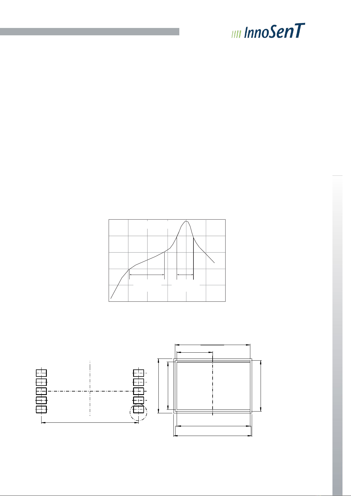
SMT GUIDELINES
The SMR device is 100% Pb-free. Therefore, Pb-free solder paste with a Pb-free re flow profile is recommended.
Do not use solder paste with active or acid-based flux. To avoid submerging the device in the solder paste, the
placement height (Z) of the device on the pick-and-place equipment should be controlled carefully. Optimally, the Z
height should be set at one-half the printed solder paste height. Maintaining board flatness (coplanarity) is important
in keeping the Z height under control.
If possible use a pick-and-place machine with a visions-alignment system for proper centering on the PCB.
For the soldering process we recommend the following:
•For optimum results the reflow oven should have nitrogen purge (we recommend 1000ppm)
•To avoid damage during assembly solder re flow attachment, follow the guidelines in IPC/JEDEC J-STD-
020D.1. The device is qualified at 260 °C re flow. The following figure shows a typical temperature profile for
Pb-free (Sn-Ag-Cu or Sn-Ag) solder and the corresponding critical re flow parameters.
•Assemble the SMR within 5 days after opening the packing
•Not assembled SMR must be dried for 500h at 40 degree Celsius; 1% r.H. before repacking in a dry pack.
220
180
150
PACKAGE FOOTPRINT
Recommended Footprint and Stencil Layout
Time
Copper
1.05
2.2
Solder
A 2.15
Paste
Recommended stencil thickness 225µm
CONFIDENTIAL AND PROPRIETARY
The information contained in this document shall remain the sole and exclusive property of InnoSenT GmbH and shall not be
Max. 260°C, Min 230°C
Min. 60sec
Max. 120sec
Min. 30 sec
Max. 90sec
21.4
2.3
Temperature (°C)
1.
6
1.5
Page
User Manual
SMR-314 / 334
Version 2.2
Experience and Reliability in Radar Technology
disclosed by the recipient to third parties without prior consent of InnoSenT in writing.
HANDLING PRECAUTIONS
To avoid damage to the devices, care should be exercised during handling. Proper Electrostatic Discharge (ESD)
precautions should be observed at all stages of storage, handling, assembly, and testing.
ESD INTEGRITY
ESD Robustness HBM = +/- 1kV according to ANSI/ESDA/JEDEC JS-001 (R = 1.5kOhm, C = 100pF) for Electro-
static Discharge Sensitivity Testing, Human Body Model (HBM)-Component Level; CDM = +/- 500V according to
JEDEC JESD22-C101 Field-Induced Charged Device Model (CDM), Test Method for Electrostatic-Discharge-With-
stand Thresholds of Microelectronic Components.
MSL RATING
The device has an MSL rating of Level 1. To determine this rating, preconditioning was performed to the device
per the Pb-free solder profile defined within IPC/JEDEC J-STD-020C.
TAPE OF SMR-314/334
The SMR-314/334 will be delivered on tape with a width of 32mm.
Labeling
SMR-3X4
CONFIDENTIAL AND PROPRIETARY
The information contained in this document shall remain the sole and exclusive property of InnoSenT GmbH and shall not be
Page
User Manual SMR-314 / 334
Version 2.2

Experience and Reliability in Radar Technology
disclosed by the recipient to third parties without prior consent of InnoSenT in writing.
Annex A
The information that will be given below is only a rough overview; for details please contact the local approval
agencies. An overview over the frequency bands in Europe can also be found in the REC 70-03 (Annex 6) which
is available under www.efis.dk
Frequency Bands in Europe
Generally the SMR-3X4 standard version can be used for all countries in Europe.
24.000 24.050 24.150 24.250
Frequency Bands in US FCC 15.249
24.000 24.250
FCC approval
This device complies with Part 15 of the FCC Rules and with RSS-310 of Industry Canada. Operation is subject to
the following two conditions:
(1) this device may not cause harmful interference, and
(2) this device must accept any interference received, including interference that may cause undesired
operation.
Warning: Changes or modifications made to this equipment not expressly approved by InnoSenT GmbH may void
the FCC authorization to operate this equipment.
Manufacturers of mobile or fixed devices incorporating SMR-3X4 modules are authorized to use the FCC Grants
and IC Certificates of the SMR-3X4 modules for their own final products according to the conditions referenced in
these documents. In this case, the FCC label of the module shall be visible from the outside, or the host device
shall bear a second label stating „Contains FCC ID: UXS-SMR-3X4 “
Le présent appareil est conforme aux CNR d’Industrie Canada applicables aux appareils radio
exempts de licence. L’exploitation est autorisée aux deux conditions suivantes:
(1) l’appareil ne doit pas produire de brouillage, et
(2) l’utilisateur de l’appareil doit accepter tout brouillage radioélectrique subi, même si le brouillage est suscep-
tible d’en compromettre le fonctionnement.
NOTICE:
Changes or modifications made to this equipment not expressly approved by (manufacturer name) may void the
FCC authorization to operate this equipment.
CONFIDENTIAL AND PROPRIETARY
The information contained in this document shall remain the sole and exclusive property of InnoSenT GmbH and shall not be
US-frequency
UK-frequency
Europe-frequency
Page
User Manual SMR-314 / 334
Version 2.2

Experience and Reliability in Radar Technology
CONFIDENTIAL AND PROPRIETARY
The information contained in this document shall remain the sole and exclusive property of InnoSenT GmbH and shall not
be
disclosed by the recipient to third parties without prior consent of InnoSenT in writing.
ORDER INFORMATION
SMR
www.InnoSenT.de
antenna
system pattern 121° x 111°
(1 x 1 Patch)
system pattern 43° x 116°
(1 x 4 Patch)
SMR-314
SMR-334
APPROVAL
This Data Sheet contains the technical specifications of the described product. Changes of the specification must
be in written form. All previous versions of this Data Sheet are no longer valid.
VERSION DATE COMMENT
1.0 13.04.2016 initial release
1.1 26.07.2016 data matrix code in outline dimensions removed
1.2 06.03.2017 changing recommended footprint; addition information in interface
1.3 10.03.2017 changing addition information in interface
1.4 30.05.2017 adding label
1.5 08.06.2017 added IC notice
1.6 21.12.2017 changing recommended footprint
1.7 25.01.2018 remove SMR-324
1.8 12.02.2018 changing handling information
1.9 20.04.2018 adding in mechanical
2.0 11.06.2018 changing order information (system pattern)
2.1 26.11.2019 formal correction to user manual
2.2 03.08.2020 new layout
InnoSenT GmbH
Am Rödertor 30
97499 Donn
ersdorf
GERMANY
Tel.: +49 (0)9528 - 9518 - 0
E
-Mail: info@innosent.de
URL:
www.innosent.de
Page
User Manual SMR-314 / 334
Version 2.2
This manual suits for next models
2
Table of contents
Popular Accessories manuals by other brands

Bona
Bona VIKING GO20 user manual

Eaton
Eaton E55 Series Instruction leaflet

Truck System Technologies
Truck System Technologies 507 FT Quick installation guide

Banner
Banner T30 quick start guide

Dorner
Dorner AquaGard 7350 Series Installation, maintenance & parts manual

Balluff
Balluff BES M18MH2-GNX50B-BT02-EXA user guide

Invacare
Invacare Infinity LoBack Support Owner's operator and maintenance manual

PCB Piezotronics
PCB Piezotronics 377A07 Installation and operating manual

SICK
SICK Bulkscan LMS511 operating instructions

AMX
AMX IRX-UM Dimensional drawing

Bartscher
Bartscher 124L Original instruction manual

Bresser
Bresser 7009970 instruction manual


