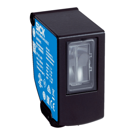
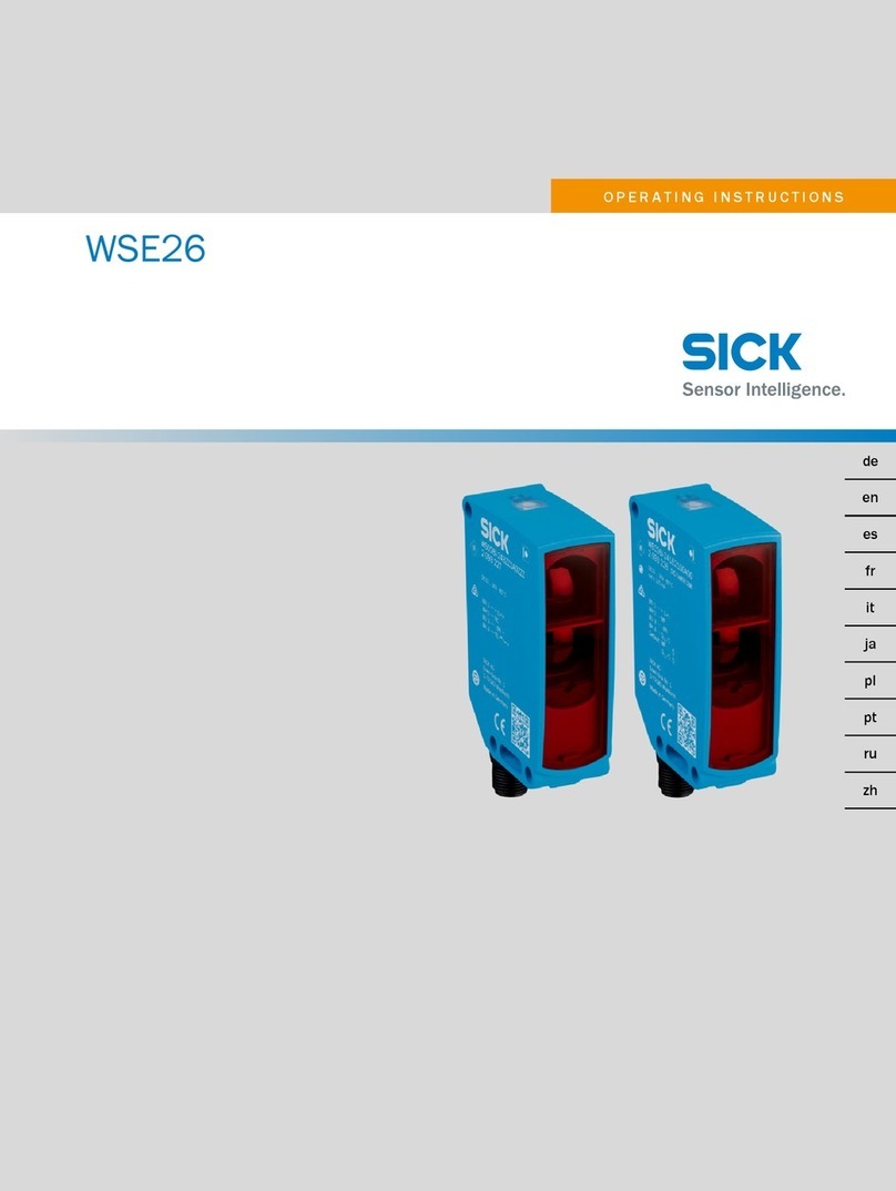
SICK Bulkscan LMS511 User manual

OPERATING INSTRUCTIONS
Bulkscan®LMS511
FLOW SENSORS
Laser volume owmeter for the throughput measurement of bulk goods
en

OPERATING INSTRUCTIONS | Bulkscan LMS511 8014829/ZNC5/2017-06-06 | SICK
Subject to change without notice
2
Copyright
This work is protected by copyright. All rights reserved by SICK AG. Reproduction of this
document or parts of this document is only permissible within the limits of the legal de-
termination of Copyright Law. Alteration or abridgment of the document is not permitted
without the explicit written approval of SICK AG.

OPERATING INSTRUCTIONS| Bulkscan LMS5118014829/ZNC5/2017-06-06| SICK
Subject to change without notice
3
Inhalt
1 About this document .......................................................................................6
1.1 Purpose of this document ........................................................................................6
1.2 Target group...............................................................................................................6
1.3 Information depth .....................................................................................................6
1.4 Scope .........................................................................................................................6
1.5 Abbreviations used....................................................................................................7
1.6 Symbols used ............................................................................................................7
2 On safety............................................................................................................8
2.1 Authorized personnel................................................................................................8
2.2 Correct use ................................................................................................................8
2.3 General safety notes and protective measures.......................................................8
2.3.1 Electrical installation work........................................................................9
2.3.2 Laser radiation...........................................................................................9
2.3.3 Damaging potential equalization currents due to different ground po-
tentials 11
2.4 Quick stop and quick restart ................................................................................. 11
2.5 Environmental protection ..................................................................................... 12
2.5.1 Power consumption................................................................................ 12
2.5.2 Disposalafternaldecommissioning ................................................... 12
2.6 IP technology .......................................................................................................... 12
3 Product description....................................................................................... 13
3.1 Special features of the Bulkscan .......................................................................... 13
3.2 Operating principle of the Bulkscan...................................................................... 13
3.2.1 Measurement principle ......................................................................... 13
3.3 Application examples............................................................................................. 14
3.4 Status indicators .................................................................................................... 15
4 Congurable functions ................................................................................. 16
4.1 Setting the belt speed............................................................................................ 16
4.2 Measurement of the volume ................................................................................. 17
4.3 Measurement of the mass .................................................................................... 17
4.4 Measurementofvolumeowrate ........................................................................ 18
4.5 Measurementofthemassowrate ..................................................................... 18
4.6 Measurement of the bulk density ......................................................................... 19
4.7 Measurement of the bulk height........................................................................... 19
4.8 Monitoring the center of gravity ............................................................................ 20
4.9 Monitoring the bulk edge....................................................................................... 22
4.10 Monitoring the conveyor belt edge........................................................................ 23
4.11 Averaginglter........................................................................................................ 24
4.12 Digital inputs........................................................................................................... 24
4.13 Digital outputs ........................................................................................................ 25
4.14 Analog module BAM100........................................................................................ 26
4.15 Data interfaces....................................................................................................... 27
4.15.1 Ethernet interface................................................................................... 27
4.15.2 Serial host interface ............................................................................... 27
4.15.3 Serial auxiliary interface/USB................................................................ 28
OPERATING INSTRUCTIONS | Bulkscan LMS511 8014829/ZNC5/2017-06-06 | SICK
Subject to change without notice
4
5 Mounting......................................................................................................... 29
5.1 Placing mounting materials ready......................................................................... 29
5.2 Selecting the mounting location ........................................................................... 29
5.3 Mounting the sensor.............................................................................................. 30
5.3.1 Direct mounting ...................................................................................... 31
5.3.2 Mounting with mounting kit 1................................................................ 31
5.3.3 Mounting with mounting kit 2................................................................ 32
5.3.4 Mounting with mounting kit 3................................................................ 33
5.3.5 Mounting with mounting bracket on existing mounting kit LMS2xx.... 34
5.3.6 Mounting with mounting bracket and mast bracket ............................ 35
5.4 Removing the sensor ............................................................................................. 35
6 Electrical installation .................................................................................... 36
6.1 Requirements for the electrical installation ......................................................... 36
6.1.1 Avoiding potential differences ............................................................... 36
6.1.2 Suitable power supply ............................................................................ 38
6.1.3 Cable lengths and wire cross-sections.................................................. 38
6.2 Carrying out the electrical installation on the Bulkscan...................................... 38
6.2.1 Supply voltage connection ..................................................................... 39
6.2.2 Connection of the digital inputs/outputs.............................................. 39
6.2.3 Ethernet interface connection ............................................................... 40
6.2.4 Serial interface connection.................................................................... 40
6.2.5 Mini-USB connection.............................................................................. 41
6.3 Wiring the inputs and outputs to the external components ................................ 42
6.3.1 Wiringnon-oatingdigitalinputs ........................................................... 42
6.3.2 Wiringoatingdigitalinputs .................................................................. 42
6.3.3 Wiring encoder inputs ............................................................................ 43
6.3.4 Input circuits IN1 and IN2...................................................................... 43
6.3.5 Connecting the outputs to a PLC ........................................................... 43
6.3.6 Analog inputs/outpus with analog module BAM100.......................... 44
6.3.6.1 Module design ..................................................................... 44
6.3.6.2 Installation of Bus Terminals on mounting rails ................ 45
6.3.6.3 Power supply BC9050......................................................... 46
6.3.6.4 Analog input terminal KL3454 ........................................... 47
6.3.6.5 Analog output KL4424........................................................ 48
7 Conguration ................................................................................................. 49
7.1 ConguringtheBulkscanwithSOPAS................................................................... 49
7.1.1 InstallingtheSOPAScongurationsoftware......................................... 49
7.1.2 Establishing communication with the Bulkscan................................... 50
7.2 CongurationoftheBulkscanusingtelegrams ................................................... 51
8 Commissioning.............................................................................................. 53
8.1 Teaching-in the reference contour ........................................................................ 53
8.1.1 Compensation of the conveyor belt level .............................................. 55
8.1.2 Optimization for conveyor belts with slits or gaps ................................ 56
8.2 Performing a test measurement ........................................................................... 57
8.3 Setting tolerances .................................................................................................. 57

OPERATING INSTRUCTIONS| Bulkscan LMS5118014829/ZNC5/2017-06-06| SICK
Subject to change without notice
5
8.3.1 Tolerance against vibration.................................................................... 58
8.3.2 Toleranceagainstreection................................................................... 58
8.3.3 Optimization for outdoor applications................................................... 58
8.3.4 Ignore measurement points below the reference contour................... 59
8.4 Monitoring of the contamination degree .............................................................. 60
8.5 Scan frequency....................................................................................................... 61
8.6 Taking a reference measurement (compensation function) ............................... 61
9 Maintenance and care.................................................................................. 64
9.1 Cleaning the front screen ...................................................................................... 64
9.2 Replacing a Bulkscan............................................................................................. 64
10 Fault diagnosis............................................................................................... 65
10.1 Response to errors................................................................................................. 65
10.2 SICK Suport ............................................................................................................ 65
10.3 Error and status indicators on the 7 segment display......................................... 65
10.4 Status indication BAM100 .................................................................................... 66
11 Technical data................................................................................................ 68
11.1 Bulkscan LMS511 data sheet............................................................................... 68
11.2 Analog module BAM100 data sheet..................................................................... 70
11.3 Dimensional drawings............................................................................................ 71
11.3.1 Dimensional drawing Bulkscan LMS511.............................................. 71
11.3.2 Dimensional drawings mounting kits.................................................... 72
11.3.3 Dimensional drawing mounting bracket for existing LMS2xx mounting
kit 75
11.3.4 Dimensional drawing mounting bracket with mast bracket ................ 76
11.3.5 Dimensional drawing analog module BAM100 .................................... 76
12 Ordering information .................................................................................... 77
12.1 Scope of delivery.................................................................................................... 77
12.2 Accessories............................................................................................................. 77
13 Appendix......................................................................................................... 80
13.1 Telegram reference ................................................................................................ 80
13.1.1 Notation and examples .......................................................................... 80
13.1.2 Logging in to the sensor/Logging out of the sensor............................. 82
13.1.3 Savingthecongurationinthenon-volatilememory .......................... 83
13.1.4 Device information ................................................................................. 83
13.1.5 Operating mode/Teach-in ...................................................................... 83
13.1.6 Measured values .................................................................................... 84
13.1.7 Measurement ......................................................................................... 84
13.1.8 System..................................................................................................... 85
13.1.9 Edge monitoring...................................................................................... 86
13.1.10 Digital inputs........................................................................................... 86
13.1.11 Digital outputs ........................................................................................ 87
13.1.12 Reference measurement (compensation function).............................. 88
13.1.13 Service data............................................................................................ 90
13.1.14 Error codes (sFA)..................................................................................... 90

OPERATING INSTRUCTIONS | Bulkscan LMS511 8014829/ZNC5/2017-06-06 | SICK
Subject to change without notice
6
ABOUT THIS DOCUMENT
1 About this document
Please read this chapter carefully before you begin working with this documentation
and the Bulkscan LMS511.
1.1 Purpose of this document
These operating instructions guide the technical personnel during the safe mounting,
electricalinstallation,congurationandcommissioningaswellasduringthemainte-
nanceofthelaservolumeowmeterBulkscanLMS511,referredtoforshortasthe
Bulkscan in the following.
1.2 Target group
These operating instructions are intended for planning engineers, developers and
operators of plants and systems in which the Bulkscan is to be used. They are also in-
tended for people who integrate the Bulkscan into a machine, initialize its use, or who
are in charge of servicing and maintaining the device.
1.3 Information depth
These operating instructions contain information about the Bulkscan on the following
topics:
◦Product description.
◦Mounting.
◦Electrical installation.
◦ Commissioningandconguration.
◦Care and maintenance.
◦Fault diagnosis and troubleshooting.
◦Conformity and approval.
WhenplanningandusingsensorssuchastheBulkscan,specictechnicalskillsare
required that are not covered by this documentation.
When operating the Bulkscan, the national, local and statutory rules and regulations
must always be observed.
YoucanndfurtherinformationontheBulkscanonlineatwww.sick.com.
1.4 Scope
These operating instructions are original operating instructions.
These operating instructions are referring to the following software versions:
Component Function Version
LMS511-20190 Firmware V2.20
SOPAS Single Device Congurationsoftware 3.3.1
For a table overview of user levels and passwords, see Chapter 7.1.2 Establishing com-
munication with the bulk scan.
Note:
Note:

OPERATING INSTRUCTIONS| Bulkscan LMS5118014829/ZNC5/2017-06-06| SICK
Subject to change without notice
7
ABOUT THIS DOCUMENT
1.5 Abbreviations used
Communication Language = proprietäre SOPAS ET communication language (ASCII =
CoLaA or binary = CoLaB)
Checksum
Light Emitting Diode
SICKOPENPORTALforAPPLICATIONandSYSTEMSEngineeringTool=conguration
softwareforthecongurationofmultiplesystemsinasingleproject
SICKOPENPORTALforAPPLICATIONandSYSTEMSSingleDevice=congurationsoft-
wareforthecongurationofasinglesystem
1.6 Symbols used
Recommendations are designed to assist you in the decision-making process with
respect to the use of a certain function or a technical measure.
Notes inform you about special aspects of the device.
Display symbols show the status of the 7 segment display of a sender or receiver:
Constant display of characters, e.g., t.
Successivedisplayofcharacters,e.g.,rst1,then2.
LED symbols describe the status of a diagnostics LED. Examples:
The LED is illuminated constantly.
TheLEDisashing.
The LED is off.
Instructions for taking action are indicated by an arrow. Read carefully and follow the
instructions for action.
Warning!
Awarningindicatesaspecicorpotentialhazard.Thisisintendedtoprotectyou
against accidents.
Read carefully and follow the warnings!
SoftwarenotesshowwhereyoucanmaketheappropriatesettingsintheSOPAScong-
uration software.
CoLa
CS
LED
SOPAS ET
SOPAS SD
Recommendations
, ,
, ,
Take action

OPERATING INSTRUCTIONS | Bulkscan LMS511 8014829/ZNC5/2017-06-06 | SICK
Subject to change without notice
8
ON SAFETY
2 On safety
This chapter concerns your own safety and the safety of the equipment operator.
Please read this chapter carefully before you begin working with the Bulkscan.
2.1 Authorized personnel
The Bulkscan must only be installed, commissioned, and serviced by adequately quali-
edpersonnel.
Risk of damage!
RepairworkonBulkscanmayonlybeperformedbyqualiedandauthorizedservice
personnel from SICK AG.
Thefollowingqualicationsarenecessaryforthevarioustasks:
Activities Qualication
Mounting and mainte-
nance
Basic practical technical training
Knowledge of the current safety regulations in the workplace
Electrical installation
and replacement
Practical electrical training
Knowledge of current electrical safety regulations
Knowledge of the operation and control of the devices in their partic-
ularapplication(e.g.,conveyor)
Commissioning, opera-
tion,andconguration
Knowledge of the operation and control of the devices in their partic-
ularapplication(e.g.,conveyor)
Knowledge of the software and hardware¬ environment in the relat-
ed application
Basic knowledge of the Windows operating system used
Basic knowledge of data transmission
Tab. 1: Qualied safety personnel
2.2 Correct use
The Bulkscan is a non-contact optical sensor for the measurement of volume, volume
owrate,mass,massowrate,determiningthecenterofgravityofbulkonconveyor
belts, monitoring of the bulk edges and monitoring of the conveyor belt edges.
It must only be used by authorized personnel and only in industrial environments.
IntheeventofanyotherusageormodicationtotheBulkscan,e.g.,duetoopeningthe
housing during mounting and electrical installation, or to the SICK software, any claims
against SICK AG under the warranty will be rendered void.
TheBulkscanmustonlybeoperatedinthespeciedambienttemperaturerange(see
"11.1 Bulkscan LMS511 data sheet“ on page 68).
2.3 General safety notes and protective measures
Safety notes!
Observe the following to ensure the correct and safe use of the Bulkscan.
• The notes in these operating instructions (e.g., regarding the use, mounting, installa-
tion or integration into the machine controller) must be observed.
• AllofcialandstatutoryregulationsgoverningoperationoftheBulkscanmustbe
complied with.
Note

OPERATING INSTRUCTIONS| Bulkscan LMS5118014829/ZNC5/2017-06-06| SICK
Subject to change without notice
9
ON SAFETY
• Thenationalandinternationallegalspecicationsapplytotheinstallationanduse
of the sensor, to its commissioning and to technical inspections repeated at regular
intervals, in particular:
◦The accident prevention regulations and work safety regulations.
◦And any other relevant safety regulations.
• The manufacturer and operator of the system in which the Bulkscan is installed are
responsibleforcoordinatingandcomplyingwithallapplicablesafetyspecications
and regulations, in cooperation with the relevant authorities.
• Thechecksmustbecarriedoutbyqualiedsafetypersonnelorspeciallyqualied
and authorized personnel and must be recorded and documented to ensure that the
tests can be reconstructed and retraced at any time.
• These operating instructions must be made available to the operator of the system
inwhichtheBulkscanisused.Thesystemoperatormustbeinstructedbyqualied
safety personnel and read the operating instructions.
• The Bulkscan does not constitute a safety component according to the EC Machinery
Directive (2006/42/EC).
• The Bulkscan is not a device for the protection of people in the context of the related
safety standards for machinery.
• The Bulkscan must not be used in explosion hazard areas.
• Any other use that is not described as correct use is prohibited.
• TheuseofaccessoriesnotspecicallyapprovedbySICKisatownrisk.
2.3.1 Electrical installation work
• Only authorized personnel are allowed to perform the electrical installation work.
• Electrical connections between the Bulkscan and other devices may only be made
when there is no power to the system.
• Select and implement wire cross-sections and their correct fuse protection in accor-
dance with the applicable standards.
Do not open the housing.
Observe the current safety regulations when working on electrical systems.
2.3.2 Laser radiation
WARNUNG WARNING AVERTISSEMENT
Laserstrahlung! Laser radiation! Rayonnement laser !
LASER PRODUKT KLASSE 1 CLASS 1 LASER PRODUCT APPAREIL À LASER DE
CLASSE 1
Wellenlänge: 905 nm
(unsichtbares Infrarotlicht)
EN/IEC 60825-1:2014
Identische Laserklasse für
Ausgabe EN/IEC 60825-
1:2007
Bulkscan® LMS511-20190:
Impulsleistung: 29,6 W
Impulsdauer: 2,9 ns
Wavelength: 905 nm
(invisible infrared light)
EN/IEC 60825-1:2014
Identical laser class for issue
EN/IEC 60825-1:2007
Bulkscan® LMS511-20190:
Puls output 29.6 W
Puls output: 2.9 ns
Longueur d‘onde: 905 nm
(lumière infrarouge invisibles)
EN/IEC 60825-1:2014
Même classe laser pour
l’édition EN/CEI 60825-
1:2007
Bulkscan® LMS511-20190:
Puissance d‘impulse: 29,6 W
Durée d‘impulse: 2,9 ns

OPERATING INSTRUCTIONS | Bulkscan LMS511 8014829/ZNC5/2017-06-06 | SICK
Subject to change without notice
10
ON SAFETY
WARNUNG WARNING AVERTISSEMENT
21 CFR 1040.10 und
1040.11
wird erfüllt, mit Ausnahme der
Abweichungen nach Laser
Notice 50 vom Juni 2007.
Complies with 21 CFR
1040.10
and CFR1040.11 except for
deviations pursuant to Laser
Notice No. 50, June 2007.
Soit 21 CFR 1040.10 et
1040.11 à l’exception de
différences sur les indications
du Laser N° 50, juin 2007.
Die im normalen Betrieb
austretende Strahlung ist
ungefährlich für die Augen
und die menschliche Haut.
The radiation emitted in nor-
mal operation is not harmful
to the eyes and human skin.
Le rayonnement émis en
fonctionnement normal n‘est
pas dangereux pour les yeux
et la peau humaine.
VORSICHT –
Bestimmungsfremder Einsatz
kann zu gefährlichen
Strahlungsexpositionen
führen.
CAUTION –
the use of controls, or
adjustments or performance
of procedures other than
thosespeciedhereinmay
result in hazardous radiation
exposure.
PRUDENCE –
tout usage de commandes,
réglages ou toute application
de procédures autres que
ceux décrits dans ce docu-
ment peut entraîner une
exposition dangereuse au
rayonnement.
Laserwarnschild
Der Bulkscan hat kein
Laserwarnschild am Gehäuse.
Laser warning sign
The Bulkscan has no laser
warning sign on the housing.
Avertissement laser
Le Bulkscan n‘a pas un aver-
tissement laser au boîtier.
Um die Einhaltung der Laser-
klasse 1 zu gewährleisten, ist
keine Wartung notwendig
No maintenance is necessary
to ensure compliance with
laser class 1.
Aucune maintenance n'est
nécessaire pour assurer la
conformité avec la classe
laser 1.
- Gehäuse nicht öffnen
(durch das Öffnen wird der
Laser nicht abgeschaltet).
- Beachten Sie die Laser-
schutzbestimmungen
gemäß
EN/IEC 60825-1:2014.
- Do not open the housing
(opening the housing will
not switch off the laser).
- Pay attention to the laser
safety regulations as per
EN/IEC 60825-1:2014.
- Ne pas ouvrir le boîtier.
(La diode laser n'est pas
désactivée en cas d'ouverture
du boîtier).
- Se conformer aux dernières
consignes de protection en
date contre le rayonnement
laser EN/IEC 60825-1:2014.
Laseraustrittsönung
Die Laseraustrittsöffnung
ist die Frontscheibe am
Bulkscan.
Siehe Abb. 1 auf Seite 11
Laser output aperture
The laser output aperture
is the front screen on the
Bulkscan.
Seeg.1atpage11
Orice de sortie
L'oricedesortiedufaisceau
laser correspond à la vitre
dans son ensemble.
Voirg.1page11

OPERATING INSTRUCTIONS| Bulkscan LMS5118014829/ZNC5/2017-06-06| SICK
Subject to change without notice
11
ON SAFETY
Fig. 1: Laser output aperture of the Bulkscan
Laser power
The laser operates at a wavelength l = 905 nm (invisible infrared light). The radiation
emitted in normal operation is harmless to human skin and eyes.
2.3.3 Damaging potential equalization currents due to different ground potentials
For electrical safety, the Bulkscan has been designed and checked according to IEC
61010-1.
Risk of injury and damage caused by electrical current!
Potential equalization currents between the Bulkscan and the peripheral devices can
have the following effects:
• Dangerous voltages on the metal housing, e.g., of the Bulkscan.
• Incorrect function or irreparable damage to the devices.
• Damage/irreparabledamageofthecableshieldduetoheatingandcableres.
Make sure the devices connected together in a system (Bulkscan, power supply,
encoder, PLC/host, etc.) all have the same ground potential.
Where local conditions are unfavorable and thus do not meet conditions for a safe
earthing method (same ground potential at all grounding points), take measures (see
"6.1.1 Avoiding potential differences“ on page 36).
2.4 Quick stop and quick restart
To stop the Bulkscan, switch it off.
Switch off the Bulkscan power supply or disconnect the M12 supply cable.
The Bulkscan retains parameters stored in the internal non-volatile memory. Parame-
ters that have not been saved as well as the measured values at the interface are lost.
To restart the Bulkscan, switch it on.
Switch on the power supply to the Bulkscan or re-connect the M12 supply cable.
The Bulkscan restarts operation with the last saved parameters.
Window of the front screen

OPERATING INSTRUCTIONS | Bulkscan LMS511 8014829/ZNC5/2017-06-06 | SICK
Subject to change without notice
12
ON SAFETY
2.5 Environmental protection
The Bulkscan has been designed to minimize its impact on the environment. It con-
sumes only a minimum of energy.
At work, always act in an environmentally responsible manner. For this reason, please
note the following information on disposal.
2.5.1 Power consumption
• The Bulkscan consumes a maximum of 25 W in operation without output loads.
• If the operating temperature of the sensor drops below 5 °C, the Bulkscan switches
on the heating. The sensor then consumes a maximum of 90 W.
2.5.2 Disposal after nal decommissioning
Always dispose of unusable or irreparable devices in accordance with the applicable
specicnationalwastedisposalregulations.
Dispose of all electronic assemblies as hazardous waste. The electronic assemblies
are easy to dismantle.
SICK AG does not currently take back devices that are unusable or irreparable.
2.6 IP technology
SICK uses standard IP technology in its products. The emphasis is placed on availability
of products and services. SICK always assumes the following prerequisites:
• Thecustomerwillensuredtheintegrityandcondentialityofthedataandrights
affected by the use of the aforementioned products.
• Inallcases,appropriatesecuritymeasures,suchasnetworkseparation,rewalls,
virus protection, and patch management, is be taken by the customer on the basis of
the situation in question.
Note

OPERATING INSTRUCTIONS| Bulkscan LMS5118014829/ZNC5/2017-06-06| SICK
Subject to change without notice
13
PRODUCT DESCRIPTION
3 Product description
This chapter provides information on the special features and properties of the Bulk-
scan. It describes the construction and operating principle of the sensor, in particular
the different operating modes.
Pleaseread this chapter before mounting, installing and commissioning the sensor.
3.1 Special features of the Bulkscan
• Non-contact,opticalmeasurementofvolume,volumeowrate,mass,andmassow
rate of bulk goods.
• Continuous, delay-free measurement.
• High resolution due to short time between the laser pulses and high angular resolu-
tion.
• Integrated determination of the center of gravity of the bulk good.
• Calculationofvolumeowrateandmassowratewithsummationtoformtotal
volume and total mass.
• Determination of bulk height.
• Monitoring of the bulk edges.
• Monitoring of the conveyor belt edges.
• Scanning range up to 20 m with 3% remission.
• Doesnotrequireaofcialapproval.
• Simple installation.
• Low maintenance costs.
User-friendlyprogramSOPASET(www.sick.com/SOPAS_ET)forthecongurationand
visualization of the parameters under Microsoft Windows®.
3.2 Operating principle of the Bulkscan
3.2.1 Measurement principle
The Bulkscan scans the surface contour of the measured object using a rotating laser
pulse. The Bulkscan calculates the distance of each point measured, and therefore the
surfacecontour,fromthetimethelaserpulsereectedbythemeasuredobjecttakes
to propagate.
During commissioning the Bulkscan initially learns the reference contour (empty con-
veyor belt) and uses this information to calculate the reference area AR(see Fig. 2). In
measuringmodetheconveyorbeltislledwiththebulk.TheareaAMcalculated from
the bulk contour is smaller than the reference area. The cross-sectional area of the bulk
AS is given by the difference between the areas.

OPERATING INSTRUCTIONS | Bulkscan LMS511 8014829/ZNC5/2017-06-06 | SICK
Subject to change without notice
14
PRODUCT DESCRIPTION
Teach-in
Conveyor belt
Measuring mode
Conveyor belt
Fig. 2: Measurement principle
AR = Reference area
AM = Area calculated from the bulkcontour
AS = Cross-sectional area of the bulk
Usingthebulkdensity(xedvalueoranalogvalue)andthebeltspeed(xedvalue,
encoder or analog value), the Bulkscan calculates the required output parameters
volumeowrateandmassowrate,aswellasthetotalvolumeandtotalmass.
3.3 Application examples
The Bulkscan is suitable for non-contact continuous detection of the bulk volume on
conveyor belts.
It can be used, for example, in the following areas:
• Monitoring transport systems for conveying coal or ore, e.g., in open-cast mines
or loading plants for:
◦Minimizing the energy consumption, maximizing the transport performance by
means of maximum loading.
◦Preventing tilted belts.
• Measuring the ash produced in power stations.
• Checking the loading of transport such as lorries, ships, railway trucks.
• Measuring volume and mass in gravel plants and other operations in the con-
struction industry.

OPERATING INSTRUCTIONS| Bulkscan LMS5118014829/ZNC5/2017-06-06| SICK
Subject to change without notice
15
PRODUCT DESCRIPTION
3.4 Status indicators
In measuring mode the sensor operates fully automatically. The diagnostics LEDs and
the 7-segment display indicate the operational status of the Bulkscan.
Fig. 3: Status indicator
Display Meaning
Bulkscan ready and error-free
Error. Pay attention to the 7-segment display.
Slight contamination. Clean the front screen.
Flashing: Heavy contamination. Clean the front screen.
Information: Check ambient conditions. Measurements continue. Pay
attention to the 7-segment display.
Warning. Measures must be taken by the operator. Measurement
has been interrupted. Pay attention to the 7-segment display.
7-segment display The 7-segment display shows diagnostics messages on errors or
faults that occur (see "10.3 Error and status indicators on the 7
segment display“ on page 65).
Tab. 2: Meaning of the status indicators

OPERATING INSTRUCTIONS | Bulkscan LMS511 8014829/ZNC5/2017-06-06 | SICK
Subject to change without notice
16
CONFIGURABLE FUNCTIONS
4 Congurable functions
This section describes the functions of the Bulkscan which can be selected via soft-
ware.
4.1 Setting the belt speed
Inordertomeasuretheow,itisessentialtodeterminethespeedatwhichthebulkis
moving on the conveyor belt.
There are several ways to transmit/transfer the belt speed to the Bulkscan.
• Setaxedandknownbeltspeed.
• Connect an encoder to the Bulkscan.
• Connect a current signal via the analog module (see "12.2 Accessories“ on page
77).
• Transmit the belt speed via telegram (see "13.1 Telegram reference“ on page 80).
The Bulkscan can monitor the belt speed and signal on a digital output if the control
range is left.
How to set a xed value for the belt speed:
Switch to the Measurement tab.
Set Fixed value as the source as in the Belt speed group.
CongureavaluefortheFixed belt speed.
If necessary, you can use a Status signal with the required Logic for the belt opera-
tion (see "4.12 Digital inputs“ on page 24).
How to set an encoder:
Switch to the Measurement tab.
Set Encoder as the source in the Belt speed group.
ConguretheResolutionoftheencoder.Thisiscalculatedfromthecircumferenceof
the measuring wheel (shaft) and the number of lines.
Measuring wheel circumference in mm
Resolution =
Number of lines
Ifnecessary,youcancongureDirectiondetection(positiveandnegativeows)via
phase or level.
How to set an analog value for the belt speed:
Switch to the Measurement tab.
Set Analog value as the source in the Belt speed group.
Congurethe4 mA point as well as the 20 mA point with the associated belt
speeds.
How to congure the belt speed signaling on a digital output:
Switch to the Measurement tab.
ConguretheBelt speed as Encoder or as Analog value.
Switch to the Interfaces tab
Click on Digital outputs to open the Digital outputs tab (see "4.13 Digital outputs“
on page 25).
Select the assignment Belt speed for the required output.
Select the required Logic.
DenetheLower limit, the Upper limit and the associated Hysteresis.

OPERATING INSTRUCTIONS| Bulkscan LMS5118014829/ZNC5/2017-06-06| SICK
Subject to change without notice
17
CONFIGURABLE FUNCTIONS
4.2 Measurement of the volume
The sensor determines the running total of the volume transported.
The sensor calculates the volume from the measured contour and the conveyor¬ belt
speed.
SOPAS indicates this value as a volume sum and the sensor outputs the sum in the
measured value telegram. On the other hand, the volume is signaled as a switching
point per volume quota reached on a digital output, e.g., one switching point per 100
m³.
Youcansmooththemeasuredvalueswiththeaidoftheaveraginglter(see"4.11
Averaginglter“onpage24).
How to congure the calculation of the volume sum:
Switch to the Measurement tab.
ConguretheBelt speed (see "4.1 Setting the belt speed“ on page 16).
ConguretheFlow averaging lter, if required.
How to congure the signaling of the volume quota on a digital output:
Switch to the Interfaces tab.
Click on Digital outputs to open the Digital outputs tab (see "4.13 Digital outputs“
on page 25).
Select the assignment Volume quota for the required output.
Select the required Logic.
ConguretheVolume quota (volume per pulse).
CongurethePulse width.
Ensure that the duration of the pause between pulses is longer than the cycle time
resulting from the scan frequency (see "8.4 Monitoring of the contamination degree“ on
page 60).
4.3 Measurement of the mass
The sensor determines the running total of the mass transported.
The sensor calculates the mass from the measured contour, the bulk density, and the
belt speed.
SOPAS displays this value as a mass sum and the sensor outputs the sum in the mea-
sured value telegram. On the other hand, the mass is signaled as a switching point per
mass quota reached on a digital output, e.g., one switching point per 10 t.
Youcansmooththemeasuredvaluewiththeaidoftheaveraginglter(see"4.13Digi-
tal outputs“ on page 25).
How to congure the calculation of the mass sum:
Switch to the Measurement tab.
ConguretheBelt speed (see "4.1 Setting the belt speed“ on page 16).
Congurethemassowrateasacalculatedvalue.
ConguretheBulk density as Fixed value or Analog value.
ConguretheFlow averaging lter, if required.
How to congure the signaling of the mass quota on a digital output:
ÄSwitch to the Interfaces tab.
ÄClick on Digital outputs to open the Digital outputs tab (see "4.13 Digital outputs“ on
page 25).
Select the assignment Mass quota for the required output.
Select the required Logic.
Note
Note

OPERATING INSTRUCTIONS | Bulkscan LMS511 8014829/ZNC5/2017-06-06 | SICK
Subject to change without notice
18
CONFIGURABLE FUNCTIONS
ConguretheMass quota (mass per pulse).
CongurethePulse width.
Ensure that the duration of the pause between pulses is longer than the cycle time
resulting from the scan frequency (see "8.4 Monitoring of the contamination degree“ on
page 60).
4.4 Measurement of volume ow rate
Thevolumeowrateisthevolumetransportedperunittime.
Thesensorcalculatesthevolumeowratefromthemeasuredcontourandthebelt
speed.
Youcansmooththemeasuredvaluewiththeaidoftheaveraginglter(see"4.13Digi-
tal outputs“ on page 25).
How to congure the calculation of the volume ow rate:
Switch to the Measurement tab.
ConguretheBelt speed (see "4.1 Setting the belt speed“ on page 16).
ConguretheFlow averaging lter, if required.
How to congure the signaling of the volume ow rate on a digital output:
Switch to the Interfaces tab
Click on Digital outputs to open the Digital outputs tab (see "4.13 Digital outputs“
on page 25).
Select the assignment Volume ow rate for the required output.
Select the required Logic.
DenetheLower limit, the Upper limit and the associated Hysteresis.
How to congure the signaling of the volume ow rate on an analog output:
Switch to the Interfaces tab.
Click on BAM 100 to open the BAM 100 tab (see "4.14 Analog module BAM100“ on
page 26).
Select the assignment Volume ow rate for the required output.
Denethe4 mA point and the 20 mA point.
4.5 Measurement of the mass ow rate
Themassowrateisthemasstransportedperunittime.
Thesensorcalculatesthemassowratefromthemeasuredcontour,thebulkdensity,
and the belt speed.
Alternativelyyoucansetthemassowrateasaxedvalueorananalogvalue.The
sensor then uses this value instead of the measured value.
Youcansmooththemeasuredvaluewiththeaidoftheaveraginglter(see"4.11Aver-
aginglter“onpage24).
How to congure the calculation of the mass ow rate:
Switch to the Measurement tab.
ConguretheBelt speed (see "4.1 Setting the belt speed“ on page 16).
ConguretheBulk density as a Fixed value or Analog value.
ConguretheMass ow rate as a Calculated value.
ConguretheFlow averaging lter, if required.
How to congure the signaling of the mass ow rate on a digital output:
Switch to the Interfaces tab.
Note
Note
Note

OPERATING INSTRUCTIONS| Bulkscan LMS5118014829/ZNC5/2017-06-06| SICK
Subject to change without notice
19
CONFIGURABLE FUNCTIONS
Click on Digital outputs to open the Digital outputs tab (see "4.13 Digital outputs“
on page 25).
Select the assignment Mass ow rate for the required output.
Select the required Logic.
DenetheLower limit, the Upper limit, and the associated Hysteresis.
How to congure the signaling of the mass ow rate on an analog output:
Switch to the Interfaces tab.
Click on BAM 100 to open the BAM 100 tab (see "4.14 Analog module BAM100“ on
page 26).
Select the assignment Mass ow rate for the required output.
Denethe4 mA point and the 20 mA point.
4.6 Measurement of the bulk density
The bulk density is the mass transported per unit volume.
Thesensorcalculatesthebulkdensityfromthemeasuredcontour,theconguredmass
owrate,andthemeasuredvolumeowrate.
Alternativelyyoucansetthebulkdensityasaxedvalueorananalogvalue.Thesen-
sor then uses this value instead of the measured value.
Youcansmooththemeasuredvaluewiththeaidoftheaveraginglter(see"4.11Aver-
aginglter“onpage24).
How to congure the calculation of the bulk density:
Switch to the Measurement tab.
ConguretheBelt speed (see "4.1 Setting the belt speed“ on page 16).
ConguretheMass ow rate as a Fixed value or Analog value.
Activate the Bulk density as a Calculated value.
ConguretheFlow averaging lter, if required.
How to congure the signaling of the bulk density on a digital output:
Switch to the Interfaces tab.
Click on Digital outputs to open the Digital outputs tab (see "4.13 Digital outputs“
on page 25).
Select the assignment Bulk density for the required output.
Select the required Logic.
DenetheLower limit, the Upper limit, and the associated Hysteresis.
How to congure the signaling of the bulk density on an analog output:
Switch to the Interfaces tab.
Click on BAM 100 to open the BAM 100 tab (see "4.14 Analog module BAM100“ on
page 26).
Select the assignment Bulk density for the required output.
Denethe4 mA point and the 20 mA point.
4.7 Measurement of the bulk height
The sensor determines the height of the bulk on the conveyor belt from the measured
contour. This function can be used to protect downstream machines from bulk which is
too tall.
Note

OPERATING INSTRUCTIONS | Bulkscan LMS511 8014829/ZNC5/2017-06-06 | SICK
Subject to change without notice
20
CONFIGURABLE FUNCTIONS
Two strategies can be used to calculate the bulk height:
Center point: The point on the bulk contour
which is vertical to the Bulkscan (0° angle)
is used.
Highest point: The point on the bulk contour
with the smallest distance to the Bulkscan
is used.
h
Fig. 4: Bulk height
The bulk height is the distance between this point and the conveyor belt.
The Bulkscan can monitor the bulk height and signal a violation of the control range on
a digital output.
Youcansmooththemeasuredvaluewiththeaidoftheaveraginglter(see"4.11Aver-
aginglter“onpage24).
How to congure the calculation of the bulk height:
Switch to the Measurement tab.
Select the required Strategy.
ConguretheBulk heightaveringlter,ifrequired.
How to congure the signaling of the bulk height on a digital output:
Switch to the Interfaces tab.
Click on Digital outputs to open the Digital outputs tab (see "4.13 Digital outputs“
on page 25).
Select the assignment Bulk height for the required digital output.
Select the required Logic.
DenetheLower limit, the Upper limit, and the associated Hysteresis.
How to congure the signaling of the bulk height on an analog output:
Switch to the Interfaces tab.
Click on BAM 100 to open the BAM 100 tab (see "4.14 Analog module BAM100“ on
page 26).
Select the assignment Bulk density for the required output.
Denethe4 mA point and the 20 mA point.
4.8 Monitoring the center of gravity
The Bulkscan determines the position of the center of gravity of the bulk from the bulk
contour. This enables tilted belts to be detected and prevents malfunctions in the case
ofunsymmetricalbeltllingorunevenmassdistribution.
The value for the position of the center of gravity is calculated in the range from 0.0 to
1.0withintheapertureangle.Theapertureangleisdenedbytheanglesontheleft
and right. A value of 0.5 corresponds to half the aperture angle (see Fig. 6). I.e., if the
h
Table of contents
Other SICK Accessories manuals

SICK
SICK MultiTask RAY10 Series User manual

SICK
SICK NAV310 User manual

SICK
SICK LFC User manual

SICK
SICK UM 18-51111 User manual

SICK
SICK GTB2 Flat Series User manual

SICK
SICK GL6L-P1 Series User manual

SICK
SICK SENSICK UM30-11111/5 User manual

SICK
SICK CS81-P3612S02 User manual

SICK
SICK GTB20 User manual

SICK
SICK UFS User manual
Popular Accessories manuals by other brands

NCTE
NCTE 5000 Series manual

Baxtran
Baxtran BR80 user manual

Minebea Intec
Minebea Intec Pendeo PR 6204 Series installation manual

HB Products
HB Products HBX Vapor Quality sensor Installation and configuration guide

Essentim
Essentim Scope 4 user guide

SunSetter
SunSetter Platinum Plus Series Owner's Manual & Installation Instructions