Innovate Motorsports XD-16 User manual

XD-16_Manual_1.3.doc
XD-16 Digital Universal Dash Display
User Manual

- 2 -
1. Overview......................................................................................................................................................... 3
2. The XD-16 Device .......................................................................................................................................... 3
The XD-16 Module................................................................................................................................................. 3
2.1. Identifying the user interface features of the XD-16 ................................................................................... 4
2.2. Included cables and devices....................................................................................................................... 4
3. Mounting and Connecting the XD-16 ............................................................................................................. 4
4. Using the XD-16 ............................................................................................................................................. 5
4.1. Displayed functions when using XD-16 as AFR/Lambda display............................................................... 5
4.2. Button Functions......................................................................................................................................... 6
5. Programming the XD-16................................................................................................................................. 7
5.1. Installing the LM Programmer Software...................................................................................................... 7
5.2. Setting up the used inputs in LogWorks..................................................................................................... 7
5.3. Connecting the XD-16 device to the computer........................................................................................... 7
5.4. Updating the Firmware................................................................................................................................ 8
5.5. Selecting the display channel ..................................................................................................................... 9
5.6. Programming the Min/Max hold functions ................................................................................................ 10
5.7. Programming the Warning/Alarm function................................................................................................ 11
5.8. Programming the Analog ‘needle’ colors.................................................................................................. 12
6. Changing the gauge face of the XD-16........................................................................................................ 13
6.1. Installing the new gauge face ................................................................................................................... 13
6.2. Create a custom label............................................................................................................................... 14
6.3. Assembly sequence of the XD-16 with foil face........................................................................................ 14
Appendix A: Specifications .................................................................................................................................. 14
Revision History....................................................................................................................................................... 15

- 3 -
1. Overview
The XD-16 is a programmable digital display used as dash mounted instrument for the Innovate Motorsports
sensor devices. The XD-16 fits into a standard 52mm (2-1/16”) gauge hole. Multiple XD-16’s can be daisy-
chained to build and entire programmable dash. XD-16 gauge faces can be user customized. The XD-16 can also
be used to initiate and control recording on the LM-1 or other Innovate Recording devices, can initiate free air
calibration for Innovate Motorsports wideband controllers and indicate wideband controller status.
In addition the XD-16 can be programmed to hold minimum/maximum values of the displayed channel and
provide warnings/alerts depending on programmable warn conditions.
2. The XD-16 Device
The XD-16 set contains the following parts:
The XD-16 Module

- 4 -
2.1.Identifying the user interface features of the XD-16
The analog pointer LED’s (21 total) act as a digital needle. The range and individual colors of this “needle” is
freely programmable.
The Function indicators 1 and 2 are used to indicate between % display (heater warm-up or O2 content) when the
XD-16 is programmed as AFR/Lambda display (default). When used to display other channels, the indicators can
be used to indicate the sign of the displayed value. By using the indicators as sign display (positive or negative)
one of the three numerical displays is not wasted to show a ‘-‘ sign. This functionality is programmable.
The main numeric display shows the numeric value of the displayed channel. When the XD-16 is used as
AFR/Lambda display it will also show the status of the wideband controller.
The light sensor allows the XD-16 to adjust its brightness to the light level of the environment. At night the full on
display would be much too bright and would interfere with the operation of the vehicle. During sunlight the XD-16
will go to maximum brightness to allow readability.
The Control Button is used to control various aspects of the XD-16 and attached wideband controller or recording
device like the LM-1.
The record indicator will blink when a LM-1 or other Innovate Motorsports recording product is attached and
actively recording.
2.2.Included cables and devices
1. XD-16 to LM-1 cable (Mini-DIN 8 to female 2.5mm Stereo). Use with patch cable (#3 below).
2. XD-16 to Computer cable (male 2.5mm Stereo to DB-9)
3. Male 2.5mm Stereo to male 2.5mm Stereo cable
4. XD-16 Terminator plug (single male 2.5mm Stereo plug)
5. XD-16 Mounting bracket, studs and nuts
6. CD with manual and programming software
3. Mounting and Connecting the XD-16
1. If not using a commercial gauge pod, cut a 52mm hole into the intended dash location.
2. Insert and mount the XD-16 and mount it with the included mounting bracket, leaving the XD-16 cables in the
back accessible.
3. Connect the RED wire from the back of the XD-16 to a switched 12V source in your car. A switched 12V
source goes on as soon as the ignition on the car is on or the engine runs. Make sure the connection is fused
with at least a 2A fuse.
4. If connecting to a LM-1, connect the “XD-16 to LM-1 cable” to the LM-1’s Serial Port. Plug the 2.5mm male
stereo end into the XD-16 Serial IN port (female 2.5 mm socket marked “IN”).
5. If connecting to an LC-1 or LMA-3, connect the male 2.5mm Stereo to male 2.5mm Stereo cable between the
Serial OUT port of the LC-1 or the Serial OUT of the LMA-3 to the Serial IN port of the XD-16.

- 5 -
6. If using a computer to datalog or download LM-1 data, connect the XD-16 to Computer cable between the
Serial OUT port of the XD-16 and the computer’s serial port.
The following diagram show how to connect multiple Innovate Motorsports devices to form a logging and display
chain. The example chain consists of a LM-1, a LC-1, a LMA-3 and 2 XD-16’s. In this case the chain has 12
channels (6 from LM-1, 1 from LC-1 and 5 from LMA-3).
4. Using the XD-16
When the XD-16 powers up it will go briefly through a sequence where it lights up all its LEDs. This is a function
and diagnostic test. Holding down the Control button during power-up will continue to light up all LEDs until the
button is released.
4.1.Displayed functions when using XD-16 as AFR/Lambda display
1. Sensor Warm-up
For example, this would indicate that he heater is warmed up to 56%. The Function Indicator 2 is lit.
2. Heater Calibration
The last digit is the count-down of the heater calibration.
3. Free air calibration in process
When shown steady, free air calibration is in progress. If blinking and not going away after 5 seconds, the LM-1
requests a free air calibration as happens after a heater calibration.
Blinking CAL can also happen if the control button is pressed rapidly 3 times. Pressing it then again, initiates a
free air calibration. If this is unintentionally pressed, the CAL request goes away after 5 seconds.
4. Normal Operation
With function indicator 1 lit this shows AFR.
5. Normal Operation very lean mixture or free air

- 6 -
Switching between and
Shows the free air content of the gas the sensor sees.
5. No Connection detected
If the display shows:
The XD-16 cannot receive data from the LM-1 or other devices. Check the cables.
4.2.Button Functions
1. Start/Stop Recording
Press the Control button once to start recording. The Record indicator light will blink.
Press the Control button again once to stop recording. The Record indictor will switch off.
2. Clear Recording Memory of LM-1
Press and hold the Control button until for Reset shows.
3. Review Min/Max hold
Press the Control button twice rapidly. The XD-16 will show the last minimum value indicated. Note that the XD-
16 will remember the minimum value even if power is switched off.
Minimum value is indicated by alternating between:
and the minimum value stored.
Holding the Control button down for a few seconds while this is displayed will reset the minimum value.
Press the Control button instead only briefly will show the maximum value indicated. It is indicated by alternating
between:
and the maximum value stored.
Press the Control button again briefly to return to normal operation.
Holding the Control button down for a few seconds while this is displayed will reset the maximum value.
3. Initiating a free air calibration
Press the Control button three times rapidly. The display will show a blinking:
If the button was press accidentally three times, wait for 5 seconds. The XD-16 will return to normal display mode.

- 7 -
Pressing the Control button while the blinking CAL is displayed will initiate a free air calibration on ALL connected
wideband devices.
5. Programming the XD-16
You will need:
1. XD-16 to Computer cable (male 2.5mm Stereo to DB-9)
2. XD-16 Terminator plug (single male 2.5mm Stereo plug)
3. A laptop computer
4. When powered by the car, the ignition of the car must be on to power the XD-16. Alternatively you can power
the XD-16 with a suitable power source between 8V and 25V. A normal 9V battery can be used to power the XD-
16.
5.1.Installing the LM Programmer Software
Put the included CD in your CD-drive on your computer and follow the instructions on screen. The Software will
be installed including pre-set directories for log-data and downloaded software. The LM Installer also puts entries
for the LM Software in the Start-Menu of your computer under the heading ‘Innovate!’.
The following items will be installed on your hard-drive
1. LM Programmer Version 3.0
This is used to program the XD-16
2. LogWorks
This is a comprehensive datalogging and analysis package to download and analyze engine data
recorded with Innovate devices. It also allows real-time logging and display.
LogWorks allows to program the relationship between sensor voltages recorded by the LM-1 or LMA-3
and the indicated values. This relationship will be programmed into the XD-16 for the selected
channel/input.
3. This manual (XD-16 Manual)
4. The LogWorks Manual
Describes how to use LogWorks for datalogging and engine analysis.
5. The RPM converter (LMA-2) Manual
Describes how to operate and use the LMA-2 RPM converter and how to connect different engine
sensors. Used for LM-1 users.
6. The current firmware for the XD-16
7. An example datalog file
5.2.Setting up the used inputs in LogWorks.
Make sure the input channels to be used by the XD-16 are correctly programmed in LogWorks as they would
show up on the LogWorks screen. Refer to the LogWorks manual for details. When programming the XD-16 the
current real time settings of LogWorks are used to program the XD-16.
- 8 -
5.3.Connecting the XD-16 device to the computer
1. Connect the Serial OUT connection with the included 2.5mm stereo to DB-9 cable to a serial port on your
laptop.
2. Connect the terminator plug (2.5mm male plug with no cable) into the Serial IN connection of the XD-16.
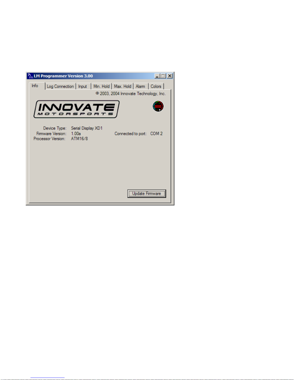
Start the LM-Programmer software. The screen should look like this:
5.4.Updating the Firmware
Click the 'Update Firmware' in the main page to upgrade to the latest firmware for the XD-16. Firmware for the
XD-16 has the extension dld. You can also download the latest firmware and software (LM Programmer and
Demo) from the Innovate! Motorsports web-site at
http://www.tuneyourengine.com
If your computer crashes during a firmware upgrade, the XD-16 has a recovery mechanism where it will be able
to retry the download again and not be disabled by half loaded firmware. Switch the XD-16 off and on again and
then try to restart the LM Manager software. The recovery mechanism is designed to be able to recover 99.9% of
the time. While we don’t anticipate this occurring, it is possible that the XD-16 will not recover correctly and may
need to be serviced at our factory. If you suspect this is the case, contact Innovate support.
- 9 -
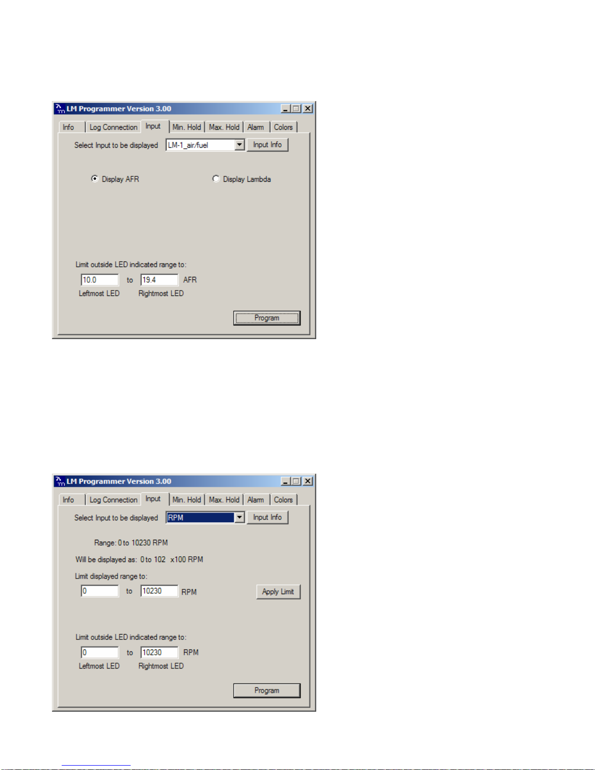
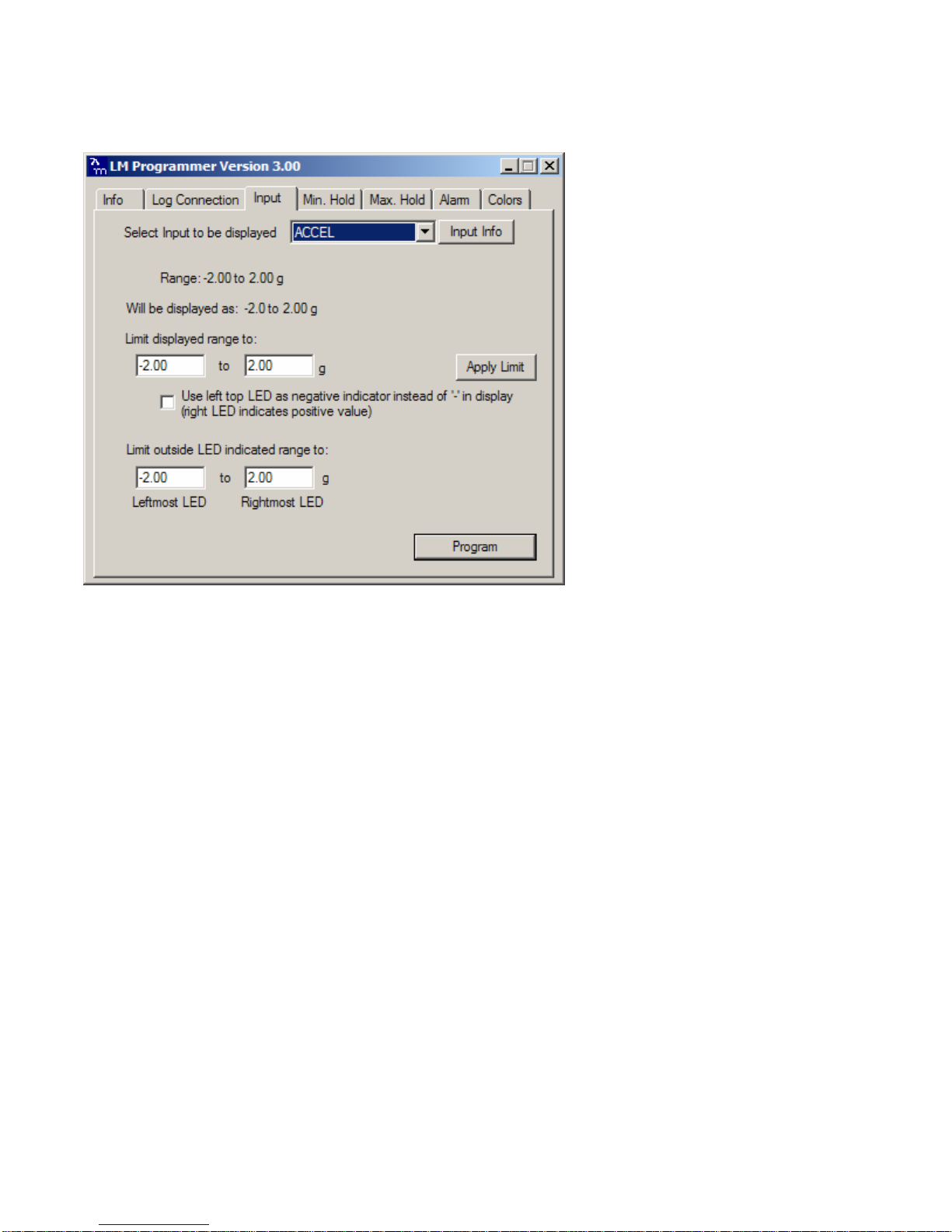
5.5.Selecting the display channel
Click on the Input Tab at the top of the window. The following screen will appear:
You can select the input channel to display, whether Lambda or AFR is displayed (when selecting a wideband
Lambda/AFR channel) and also you can set the range of the analog ‘needle’ LEDs. Press the program button
when you are finished.
If you select something other than a Lambda/AFR channel you will first need to connect all your MTS
devices or LM-1 to LogWorks and complete a real-time log. LogWorks compiles channel information
through this process. Exit LogWorks and reconnect to LM Programmer. The list of available
devices/channels will be now be selectable from the ‘Input’ tab. If you select something other than a
Lambda/AFR channel, the display will change to:
- 10 -
As you can see here, the display will indicate in 100 RPM. This might be too coarse for many applications. The
limit is there because the XD-16 can only display 3 digits. By applying a limit (for example to 0…9990 RPM the
XD-16 can display the RPM in multiples of 10 RPM. If a channel is selected that has both positive and negative
values, a different screen will show:
This allows you to use the Indicator 1 and 2 LEDs as negative value indicators to preserve the 3-digit resolution of
the XD-16.
5.6.Programming the Min/Max hold functions
Click on the Min. Hold or Max. Hold Tab on the top of the window. The following screen will show up:

- 11 -
Programming the Min or Max hold function should be pretty self evident. You can enable the function. You can
also make the hold function depending on another channel. In this example the Max hold function will be
programmed so that the leanest AFR is only stored during WOT operation and only if the condition persists for
more than 0.2 seconds. In this case AFR was used as input and you don’t want to store the leanest AFR during
closed throttle where the injectors cut off. Any channel can be programmed as dependency. You can program
any minimum persist time between 0 and 10 seconds.
5.7.Programming the Warning/Alarm function
Click on the Alarm tab on the top of the screen.
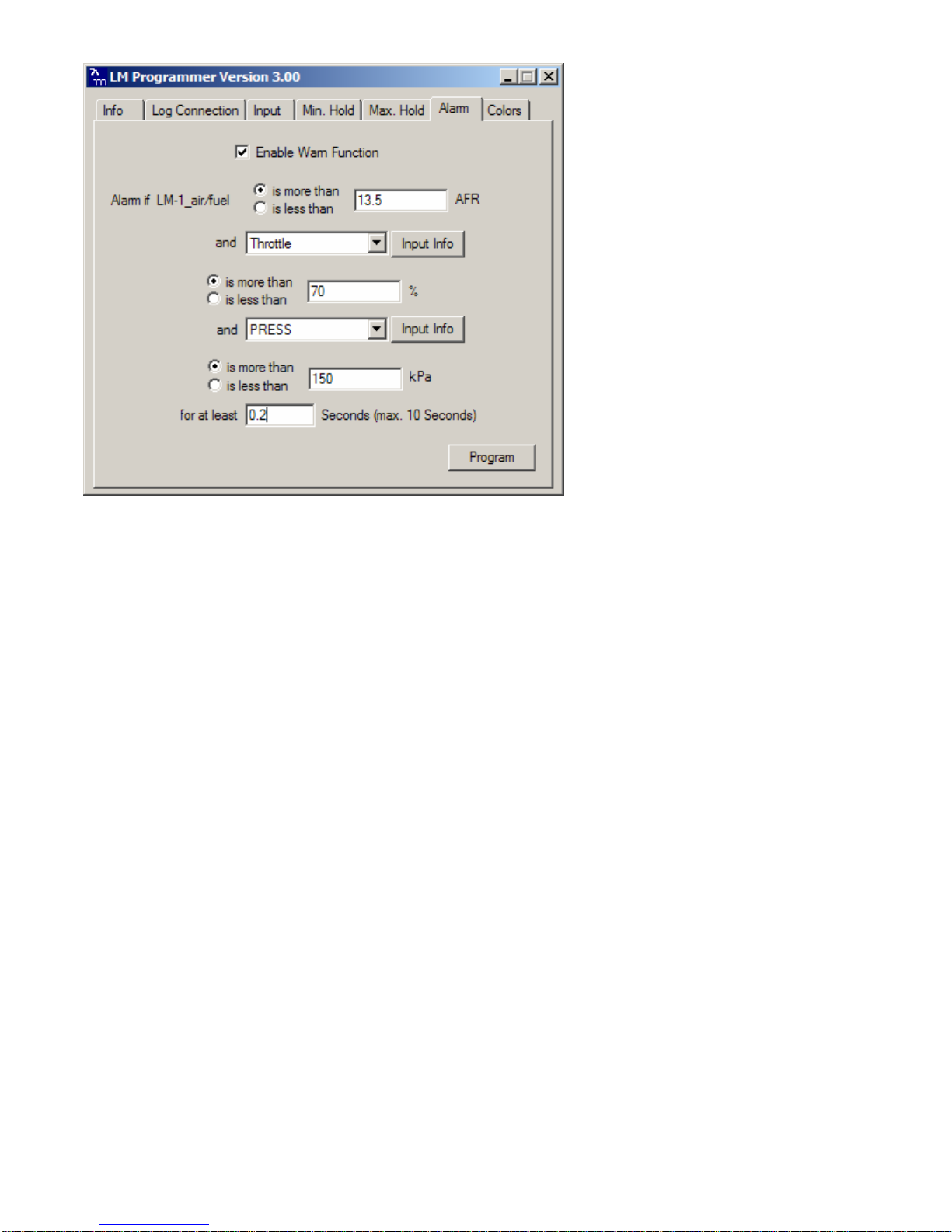
- 12 -
Again, the programming is very similar to the Min/Max hold programming as described in 4.6.
Except here the Alarm condition can be programmed to be dependent on two other channels and time.
During an Alarm the XD-16 will flash the indicated value and the analog needle LEDs at maximum brightness until
the Alarm condition goes away.
- 13 -
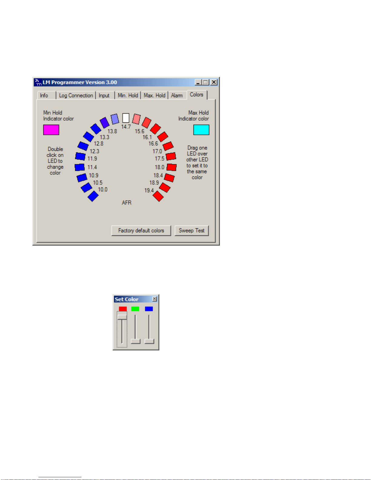
5.8.Programming the Analog ‘needle’ colors
Click on the Colors tab.
This shows the current color settings for all the 21 LEDs plus the indicator colors used when reviewing Min/Max
hold.
To change the color of an individual LED, double-click with your mouse on the LED to change. The following
dialog box will show up:
The currently selected LED is also highlighted.
By changing the sliders for red, green and blue any color out of a set of 32767 colors can be created. Any color
can be created by mixing red, green and blue light at varying ratios. The XD-16 can be programmed for 32
different values for each red, green and blue. And 32x32x32 is 32768. But black (all off) is hardly used.
While moving the sliders the simulated LED on the screen changes color and also the appropriate LED on the
XD-16 at the same time. Because computer screens use a different technology to create colors than the XD-16,
the actual colors on the XD-16 can be different than the screen colors.
With the sweep test button the XD-16 will sweep through all LEDs from left to right to give you and indication on
how the color scheme you programmed will look in real life.
To change multiple LEDs to the same color, just program one LED. Then drag this LED over the other LEDs you
want to program to the same color.
- 14 -
6. Changing the gauge face of the XD-16
When you use the XD-16 to display different channels than AFR or Lambda, you very likely want to change the
gauge face. As the LM-1/MTS system can be programmed for any 0..5V sensor, the possibilities are endless.
Because not every possible use can be anticipated, the XD-16 is designed to allow user customization.
6.1.Installing the new gauge face
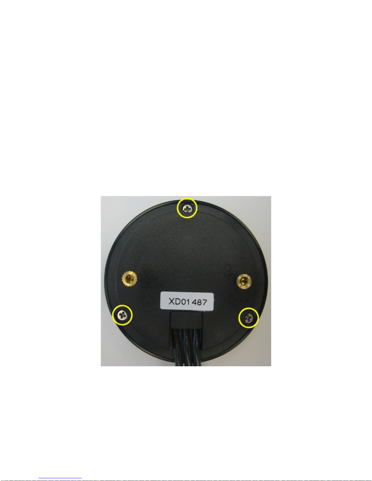
1. Lay the XD-16 face down on a table and remove the three Phillips screws from the outside rim of the
back plate.
2. Carefully lift out the back plate with the electronics package from the bezel.
3. Laying the electronics package on its back, first place the gauge face followed the glass and bezel. *Be
sure to remove protective film from the gauge face. This can be done easily with a piece of scotch
tape. Make sure every piece is positioned correctly on the button shaft.
4. Carefully flip the complete assembly and line up the screw hole of the bezel with the screw hole of the
back plate ensuring that everything slides into the bezel correctly.
5. Holding the assembly together with one hand, test the operation of the button and as necessary, adjust
by rotating bezel, glass, and gauge face.
6. Reinstall the 3 Phillips screws.

- 15 -
6.2.Create a custom label
Note:
To customize you will need to use a blank white gauge face (supplied with every XD-16).
Innovate Motorsports will provide downloadable .pdf file templates for the most common sensors at:
www.innovatemotorsports.com.
Print these templates on clear overhead foil suitable for your printer. Any stationary store carries those.
Depending whether you use an inkjet or laser printer, different foils will be needed.
1. ExactoTM knife or razor blade (or scissors)
2. Piece of plywood or sturdy cardboard as cutting background. (Do not use the kitchen table).
3. A 1/8” hole punch. Leather equipment stores or horse tack stores carry those.
4. A small Phillips screw-driver.
5. Blank white XD-16 face (included)
6.3.Assembly sequence of the XD-16 with foil face
Appendix A: Specifications
Supply voltage range 8V to 25V
Current draw < 600 mA *
Weight 3oz / 82g
Serial port speed 19.2 kb
Max serial port cable length 15 ft.
* Current draw depends on outside brightness and number of LED segments lit.

- 16 -
Revision History
1.0 – 2/5/05
Initial release
1.1- 3/16/05
Corrected misc. errata.
1.2- 4/11/05
Corrected section 2.2
1.3 – 2/06/06
Added XD-16 information
Table of contents


