INON Z-240 User manual
Z-240
Type4
User Manual
(Basic Operation)
Optical Connection"
S-TTL
"Simple Shooting
Be su
re
that you have read and understood "Safety Precautions"
desc
ri
bed
in
separate paper before using Z-240.
This English Manual
is
provided only far INON approved export products.
This produci carries officiai customer support (technical suppo
rt
,
wa
r
ra
nty
service and repair/overhaul)
by
INON authorized distributors/dealers or
by
INON
lnc.
via
INON authorized distributors/dealers. Please contaci your INON
authorized distributor/dealer when you need customer support.
Features not mentioned
in
th
is manual are explained
in
separate User
Manual (Advanced Operation) .
Be
fore reading t
he
separate ma
nu
al,
complete understanding and familiarization with contents of
th
is Basic Manual
is
highly recommended
lntroduction
Thank you
lor
purchasing
IN
ON
Z-240 Type 4.
The Z-240 Type 4
is
an
underwater S-TTLAuto Strobe with Guide Number 24(air
IS0100
/m). Main features of Z-240 are as follows;
• Equipping Nikonos V type 5 pin synch connector supports conventional
electrical connection with a camera system as well as optical
co
nnection
where the Z-240 flashes
in
sync wilh camera's built-in flash or other
external strobe.
• Fully automatic exposure control (S-TTL Auto* )
wi
lh compatible digitai
cameras.
• Wireless connection capability (* l triggered by camera's built-in flash
without a fiber op
ti
cs.
• External Auto C* )IManual
C*l
exposure control
lor
sop
hi
sticated lighting.
• Con
ve
ntional TTL-Auto exposure(
*l
available tor compatible film
ca
mera
system
un
der optical1electrical connection.
• Manual+TTL Auto(* ) exposure controls maximum flash
ou
t
pu
t and
eliminale overexposure
in
particular situation where
co
nventional TTL
exposure has problem to get righi exposure.
• Shutter linked auto
OFF
Focus Light support
i.ng
auto/manual focusing.
Usable as independent diving light wilh 180lumen inlensity/20°coverage.
• Clear Photo System(PAT P.
*l
compatible. Clear Photo System
effectively eliminates "backscatter", reflec
ti
on of suspended particles
• Advanced Canee! Circuii (
PAT
P
.*
) supporting easy and comfortable
External Auto/Manual shooting
lor
1 -2 time pre-flash type digitai camera
Please refer separate User Manual "Advanced Operat
io
n" far detalls
of
each feature
Make
sure
to
complete
from
STEP1
through
STEP
4
before
starting
to
use
Z-240
[STEP 1] Check equipments I accessories of Z-240 and necessary optional parts
[STEP 2] Read carefully I Safety PrecautionsJ I Compatible battery, operational
limitation on flashing/Focus LightJ on separa
te
paper.
[STEP 3] Being familiar with
yo
ur camera/housing
[STEP 4] Master Basic operalion of Z-240
(Th
is manual)
[STEP
5]
MasterAdvanced operation of Z-240 (Separale Manual)
l
All
119111
•••••v•d
N o
o•n
o r 1111•
manu•I
,.,.,
O•
1•0•0<111c10
or
1<•ntm111ea
1n
•ny
l
orm
or
o,
•"1
m
ea
n •
•l•c11on1c
or
mec11an1ca1
1ncl110•n11
p1101ocooy
record•n11
on
enr
1nlorme
1
1on
uorage
•no
rer11e••I
ty$1e
m
no
•
-nown
or
10
be
lnven1e<I
w11110111
o•rm11
..
on
In
"""'"I
!rom
!NON
lnc
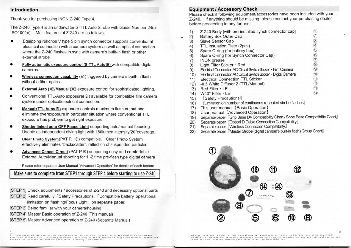
Equipment
I
Accessory
Check
Please check
il
following equipment/accessories have been included with your
Z-240.
li
anything should be missing, please contaci your purchasing dealer
before proceeding
lo
any further.
1) Z-240 Body [with pre-install
ed
synch connector cap] G)
2) Battery Box Outer Cap
(g)
3)
Slave Sensor Cap @
4) TTL lnsulation Plate (2pcs) @
5) Spare O-ring (tor battery box) @
6) Spare O-ring (lor Synch Connector Cap)
~
7) INON grease ([)
8)
Light
Fi
lter Sticker · Red ®
9)
Electr'cal
Conredion
AC
Cirrun
5'Mtd1
Sicker
·
Film
Camera
@
1o)
Electr'cal
Conredion
AC
Cirrun
Swttch
Sicker
.
Digilal
Camera
(@
11
) Electrical Connection TTL Sticker
([j)
12) -0.5 White Diffuser 2 (TTUManual) 1
13) Red
Fi
lter ·
LE
@
14) W40° Filter ·
LE
@
15)
rr
satety PrecautionsB
16l
rr
umitation
on
number
ot
continuous
repeated
strobe flashesB
17)
Th
is
user manual (Basic Operation]
18) User manual (Advanced Operation]
19)
Separate
paper
rr
Gnp
B
ase
D4
Compatibility
Chart
I
Shoe
B
ase
Compatibility
Cha
~
20)
Separate
paper
rr
optical D
Cab
le
Connection
Compatibility
B
21
l
Separate
paper
rrw
ireless
Connection
Compatibi
l
ity
B
22)
Separa
te
paper
rrMa
ster
Strobe
(
digilal
camera
's
built~n
flash
)
Group
Cha
~
@)
® @
•
=~
@ :@
.
(/)
.
..
__
.....
@
@ -
o -
@ @
@)
®
All
t1gn1
••••'"•"
N o
piri
ot
1n11
m•nu•I
m•y
be
••P•ottuc•tt
or
ll•nsm111ett
In
•ny
lorm
O•
by
•ny
me•ns
•l•C
l
ton•c
o•
mecllanlcal
1nc1utt1ng
pllorocopy
••cortt1ng
on
•ny
lntorr•,.1ton
slOlllJ•
1no
••lll•w•I
•Y•l•m
now
known
or
to
bo
1nven1oa
w11llou1
P•rm1111on
on w
ttr1ng
trom
I N O N
!ne
Confirming
Necessary Optional
Products
Please check if you have necessary optional items below
to
use the Z-240.
a) 4 x
AA
size battery :
AA
"eneloop"(HR-3UTG)
is
recommended
=>P.20
b)
When using with a
com
pact digitai camera
Refer
to
P.
15
to
determine connection method and prepare necessary
compatible products lor connection and Z-240 installation.
<D
~
Wireless
Connectionn
1)''Wi
rel
ess Connection Compatible Base Set"
2)"Wireless Connection Kit"
~
~
Optical
D Cable Connectionn
=}P.
16
=}P.
17
1) "Wireless Connection Compat
ibl
e Base Set'
',
=}P.
17
or "Base" parts + "Arm" parts =}P.18
2) "
Optical
D
Cable
"
parts
(+optional
parts
to
connect "
Optical
D
Cab
le"
parts)
=}P.18
c)
When using
with
a camera system/external strobe other than compact digitai
camera systems
Referto (Basic Operation]
P.15
/ (Advanced Operation] P. 18 to determine
connection method and prepare necessary compatible products
lor
connection and Z-240 installation.
As
of July 2009
• Z-240 is designed and manufactured for use in severe conditions. Before shipping, all
strobes are pressure
te
sted in water and fully checked for proper function.
lo
ensure your
Z-240 maintains optimum performance, in
addition
to
the
pre
and
post
dive
handling
recommendations
,
maintenance
procedures
,
and
recommended
storage
conditions
,
it
is
also
necessary
that
the
strobe
rece
ive
periodic
overhaul
at
INON
.
• INON lnc. cannot indemnify anyone for any loss/damage regardless of whether
il
is
directly/indirectly caused by malfunction/fiooding of the produci.
• Please take test shots before using Z-240 underwater to make sure
il
works properly
especially before taking important shot(s).
• All company names and product names
in
this manual are registered trademarks and/or
trademarks
of
their respective owners.
AH
11ghl
r•111-.•o
No
p•rt
ot
lh
t•
m1n
..
1I
may
b
fl
reproaue
ell
or
1111n1m1nea
In
tny
torm
or
by
1ny
mean•
1lec11onle
or
mechanlc.i
1nclu01n9
pho
l
ocopy
reeorO
•
ng
on
1ny
•n!O•m•11on
1101age
ano
reu1ev11
•Y•lem
now
~nown
Of
IO
b•
lnv1nlld
w!ll'I
OU I
pefmt111on
in
wrillng
!
rom
I N O N
ln
e
Manual Organization
Th
is
Manual (Basic Operation)
is
organized
as
follows.
,
To
ensure proper use, before using please read this Manual thoroughly, and
understand the product's features and limitations with each camera system.
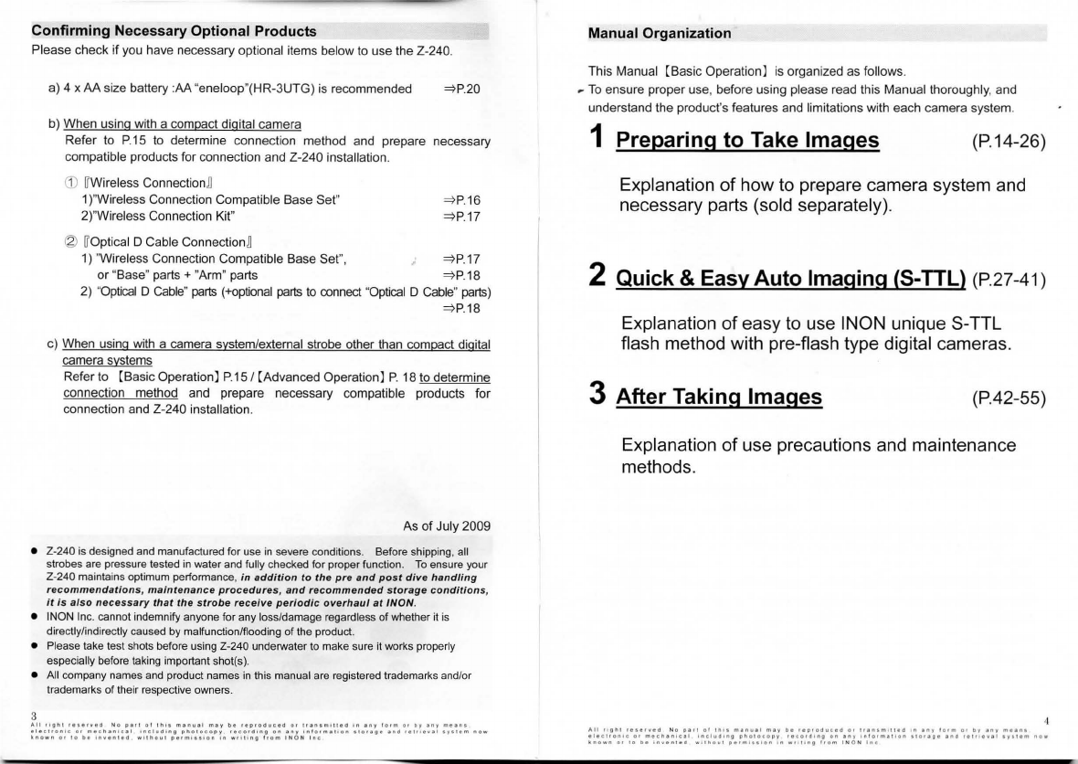
1 Preparing
to
Take lmages (P.14-26)
Explanation
of
how to prepare camera system and
necessary parts (sold separately).
2 Quick & Easy Auto lmaging (5-TTL) (P.27-41)
Explanation
of
easy to use INON unique S-TTL
flash method with pre-flash type digitai cameras.
3
After
Taking lmages (P.42-55)
Explanation
of
use precautions and maintenance
methods.
Alt
11gn1
1111,.ed
N o
peri
ot
lhts
manu11
mty
be
••proo
..
citll
or
1f1n1m11uo
on
1ny
rorm
or
by
any
meant
•leelron!e
o•
meen1nleal
1nclud•n9
pho1ocopy
recordlng
on
any
1nlorma11on
Hor1g1
1no
r11nev1t
•y111m
now
iinown
01
lo
bi
1n-.1nUd
w l
lhOu!
perml1l!Ot1
lii
w11t1ng
!rom
INON
lne

Contents
Contents
..
Z-240 Names of Parts .
Measu
re
s
lo
Prevent Accidental Flooding
........... 5
......... 6
......
11
1 Preparing
to
Take
lmages
..
...
....
....
...........15
Explanation of Compatible Camera Systems
..
......... 16
Parts necessary for connection I attachment (sold separatel
y)
....
18
"Wireless Connection compatible base" set . ················ ......... 18
Wireless Conenction
Kit
.
"Optical O Cable"product..
...
.
"
Ba
se
" parts + "Arm" parts .
..
.
Z-240 compatible "AA" batte
ri
es
..
lnstalling Batteries
Checking O-ring
Attaching I Connecting
to
Camera System
.............. 19
..... 19
19
.......
21
.22
............
23
. 24
2 Quick & Easy Auto lmaging......................28
3
5
Ba
sic Light Adjustment Methods
...
....... 29
Limitation
on
Focus Light continuous mode and flashing ....................
..
....
...
31
Shooting with S-
TIL
Auto Exposure..
Adjusting Strobe Output
in
S
-TIL
Auto
. 32
.. ..
...
37
After Taking lmages .......
..
..
.
..
..............
....
.43
Handling .
Alter-use maintenance
...
Storage Method ........................
Regarding Batteries
..
Overhaul
Alter Service .
...... 44
............. 46
..... 47
...
48
....... 50
........
51
"Il
ngn
1
••••fvlO
No
p111
ol
rn
1•
m1n<11I
may
b•
••oroo<1c1a
or
Lt1nsm11110
'"
1ny
!
orm
01
n,
any
means
11tc11onteo
01
m1cllanlc1I
111c1uo1n11
01101ocooy
•ecordong
on
any
111lo•m111on
s 1
o••!I•
1nd
r1t111v11
•yHem
now
\no"'"
(H
10
bi
111•111110
wll~out
p11mll•<On
In
wlillng
!
rom
I N O N
lnc
Z-240 Names
of
Parts
ISee separate manual (Advanced Operation]
lor
detail of each partj
2
3
1: Flash
Tu
bes
2:
Focus
Light
3:
Light
Adjustment
Sensor
4: +1/4EV
Compensation
Switch
1
4
5
When using External Auto Mode, with strobe's Aperture Switch set to a
particular
va
lu
e, add
+1
/4EV light output compensaiion
to
thai set value.
5:
Slave
Sensor
Attach
an
"Optical Cable/Optical O Cable/Optical O Slave Cable" from
here
to
th
e camera I housing I ano
th
er external strobe for optical
co
nn
ection or attach a "Mirror Unii (strobe
)"
included
in
optional Wirefess
Connection
Kit..

7
86
12
14
1315
17
~
·-
(
•
7
18
;
6:
Main
Mode
Switch
Turns the Z-240 ON/O
FF
a
nd
swit
ch
between
IT
S-
TTL Auto] ,
IT
S-TTL Auto
"Low"] ,
IT
External Auto] , and
IT
Manual] I
IT
Manual + TTL Auto] modes.
7:
EV
Contrai
Switch
Adjust
li
ght output in
IT
S-TTL Auto] ,
IT
S-TTL Auto "Low"] modes. Set
aperture
va
lu
e
in
IT
External Auto] mode. Set light output
in
IT
Manual]
mode and maximum
li
g
ht
output
in
IT
Manual + TTLAuto] mode.
8:
Focus
Light
Switch
Switch between below three modes:
*O
FF
mode (without using Switch}
*Single mode (push Switch once and release)
*Continuous mode (push Swit
ch
and rotate
lo
lock}
12:
Battery
Box
13:
Battery
Box
lnner
Cap
14:
Battery
Box
lnner
Cap
Screw
15:
Battery
Box
Outer
Cap
16: 6mm
threaded
socket
tor
Adapter
I
Joint
17:
Synch
Connector
18:
Synch
Connector
Cap
:1
1
~:
1
1
~
0
11
~
,;•:,•
•,;::
n
a~
~
e:~'
1
1
n°c
11
~~:
~gm;
~
:i"o
1c
::;
~!c'o
'
rPo',~~
u
~:d e~~
:~~
;~;!',\!
~
1
s~
o~,~~
:0
.'
;'o
",',
tDr
~.
~:r
~·
s
~: ~
n o w
known
or
10
b"
•n•en
l
ed
w•lhoul
pe1m1•
•
•on
1n
W1t1'n11
!rom
IN
O N
lnc
-----10~
7
g
8
9:
Advanced
Cancel
Circuii
Switch
Press and lock the button lo turn Advanced Cancel Circuii O
FF
,
when
in
IT
External Auto] and
IT
Manual] modes under optical
co
nnection.
In
[S-TTLAuto] m ode Advanced Cancel Circuii
is
automatically deactivated so swit
ch
operation
is
noi necessarv.
When using elec
tri
ca
l
co
nnection, set depending
on
your
camera/camera system and flash mode you use.
10:
Strobe
Ready Red
Lamp
Monitoring charge status and
sh
in
es wh
en
strobe charge complete.
11
:
"AUTO
OK
" Green
Lamp
Shines
in
dicating proper flash
in
g with
in
auto exposure range
in
IT
S-TTL Auto] ,and
IT
External Auto] modes.
8

9
Al!
11gn1
,.,.,
...
.,
No
P•rl
01
1n11
man11al
may
oe
1epr11<111ceo
o•
1ran1monell
1n
any
torm
o•
l>y
any
means
elecuon1c
O•
mecn1n1c1I
1nc!11C1•n11
pnotocopy
recordln9
on
1ny
1n l
o1mellon
1101•11•
end
re
1
11e•••
1yitem
now
~nown
or
10
be
rn•
ented
w11no111
P••1'lll1•on
In
wt111n11
!rom
I N O N
lnc
19
20
.
INO
...
21
-e.
1
S1<1<>
e
.
•
.
~9~
23
(
24
19
: -0.5
White
Diffuser
2 (TTL/Manual)
20: Red
Filter
· LE
21
: W40°
Filter
· LE
22:
Sensor
Cap
23:
Battery
Box
Spare
O-ring
24:
Synch
Connector
Cap Spare O-ring
25: INON Grease
26: TTL
lnsulating
Plate
29
25
:
26
27
9
30
28
-
27: Electrical Connection
AC
Circuit
Switch Sticker • Film Camera
28: Electrical Connection
AC
Circuit Switch Sticker · Digitai Camera
29: Electrical
Connection
TTL
Sticker
30:
Light
Filter
Sticker
• Red
Adhere
lo
Focus Light for proper light control for ultra macro shooting
in
[S-TTLAuto] I [S-TTLAu
to
"Low"] modes.
Also attach
so
Focus Light does noi frighten shy subjects
as
much.
lO
"''
•lgh!
••••••ed
N o
pet1
"'
1n11
m1nu11
may
11e
1ep•oauceo
or
11en1m111ea
'"
any
lo•m
111
by
eny
means
elec1ron1c
ot
mecnen1c1I
1ncl11111ng
pllotocopy
1eco•<l•n11
on
eny
1ntorma11on
11ora9e
ano
••tfl•••'
1y.iem
now
•nown
ot
10
be
1n•ent1111
w11ne1111
perm111lon
I n
wrl11ng
l1om
!N
O N
lnc
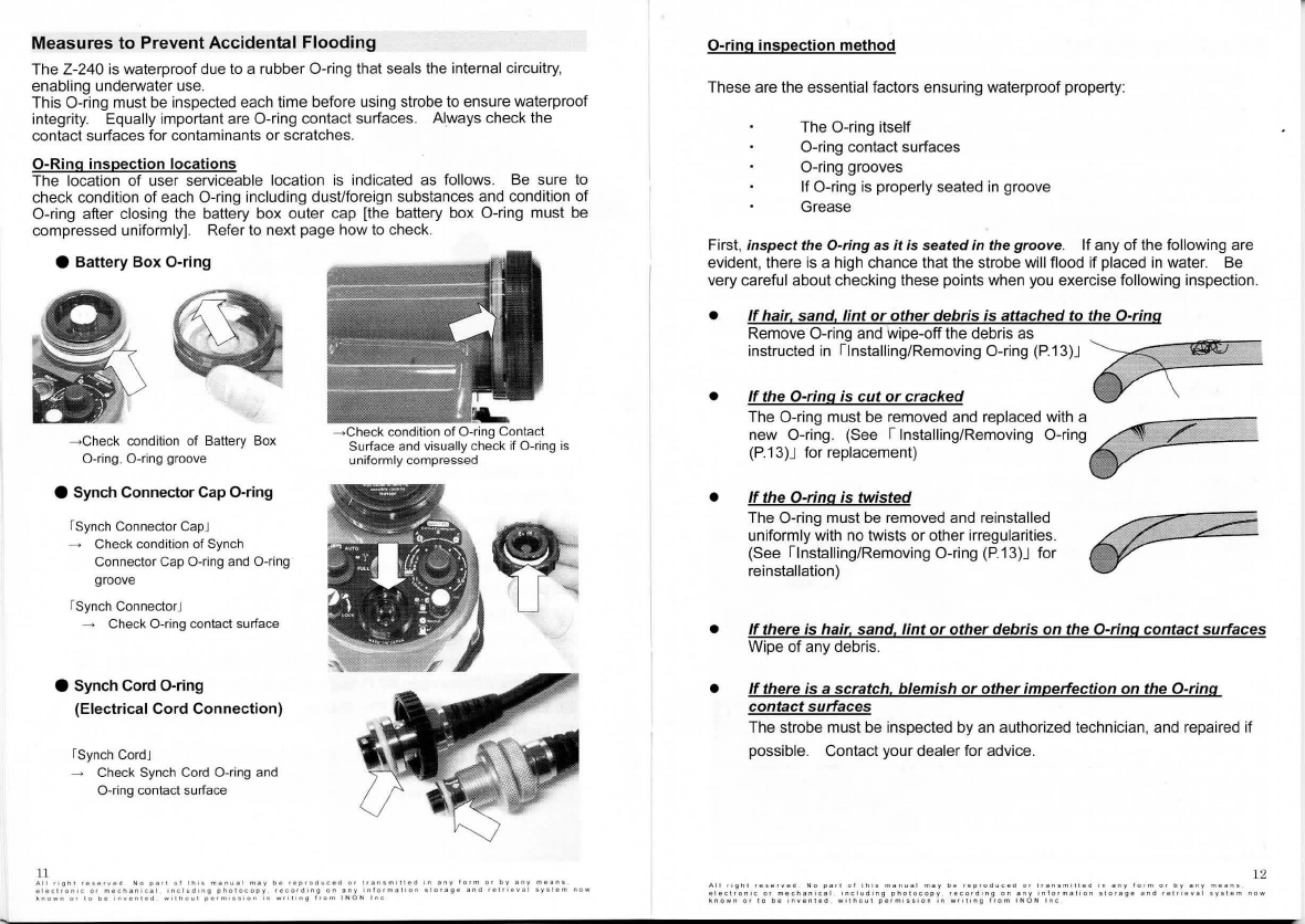
Measures
to
Prevent
Accidental
Flooding
The Z-240
is
waterprool due
to
a rubber O-ring that seals the internal circuitry,
enabling underwater
us
e.
Th
is
O-ring must be
in
spected each time belore using strobe to ensure waterprool
integrity. Equally important are O-ring contaci surfaces.
Al
_ways check the
contaci surfaces
lor
contaminants or scratches.
O-Ring
inspection
locations
The
lo
cation
ol
user serviceable location is indicateci as lollows. Be sure
to
check condition
ol
each O-ring including dust/loreign substances and condition
ol
O-ring alter closing the battery box outer cap [the battery box O-ring must be
compressed unilormly]. Reler
to
next page how
to
check.
11
e Battery
Box
O-ring
-+Check condition of Battery Box
O-ring, O-ring groove
e Synch ConnectorCap O-ring
rsynch Connector CapJ
Check condition
of
Synch
Connector Cap O-ring
and
O-ring
groove
rsynch ConnectorJ
~
Check O-ring contaci surface
e Synch Cord O-ring
(Electrical Cord Connection)
rsynch CordJ
Check Synch Cord O-ring and
O-
ring contact surface
-Check conditi
on
of O-ring Contact
Surface and visually check if
O-r
ing is
uniformly compressed
A
ll
rlgn1
•e•e•veO
N G
P•rt
o !
1n11
man
.. a l
may
be
•ep1oa
..
ce<I 01
tr~n1m111ea
In
an
y
!orm
Ot
by
""Y
mean1
elec11on1c
o•
mecnanlcal
•ncl
..
du>g
photocopy
reco•Olng
on
any
ln
l
ormal!on
1
lorage
ana
reuleval
1y1
1em
now
k
nown
o< l o
be
lnvfln1ed
wllnou!
pe1mo1slon
In
W!il•ng
!•Om
I N O N
lnc
O-ring
inspection
method
These are the essential lactors ensuring waterprool property:
The O-ring
it
se
ll
O-ring contaci
su
rfaces
O-ring grooves
Il
O-ring
is
properly seated
in
groove
Grease
Fir
st,
inspect the O-ring as
it
is seated in the groove.
Il
any
ol
the lollowing are
evident, there is a high chance thai the strobe will fiood
il
placed
in
water. Be
very careful about checking these points when
you
exercise
lo
ll
owi
ng
inspection.
•
•
•
•
•
lf
hair. sand,
lint
or
other
debris
is
attached
to
the
O-ring
Remove O-
rin
g and wipe-off the debris as
in
structed
in
linsta
lling/Removing O-ring (P.13)J
~
lf
the
O-ring
is
cut
or
cracked
V \
The O-ring musi be removed and replaced with
a~
new O-ring. (See 1lnstal
lin
g/Removing O-ring_
..
_·
.
/"._
(P.13)J
lor
replacement)
··•
•.··.·
lf
the
O-ring
is
twisted
The O-ring musi
be
removed and reinsta
ll
ed
uniformly with no twists or o
th
er irregularities.
(See ilnstalling/Removing O-ring
(P
.13)J
lor
reinstallation)
lf
there
is
hair
,
sand
,
lint
or
other
debris
on
the
O-ring
contact
surfaces
Wipe of any debris.
lf
there
is
a scratch,
blemish
or
other
imperfection
on
the
O-ring
contact
surfaces
The strobe must be inspected
by
an authorized technician, and repaired if
possible. Contaci your dealer lor advice.
12
All
ngn
1
re1etYaa
N o
pari
o!
tn
os
manual
may
be
1eproaucea
or
1tan1mt1tea
on
any
lotm
or
DV
any
mean
s
elecnonoc
or
mecnan
1c a l
onclud•ng
pno1ocopy
feco
r d 1
nQ
o n
any
ontormaloo
n 1
torag
e
and
1e1
ri
e•al
sys
tem
now
~nown
o•
to
be
1n~entea
wltnout
permlss•on
'"
w•ot•ng
l•om
INON
lnc

O-ring Maintenance Method
Periodically
re-grease the
0-rings
fil1l.y
using
the
supplied
/NON Grease, to
protect
O-ring
and
increase
water
resistance
.
/NON
yellow
0-rings
are
compounded
with
a
special
type
of
oil
which naturally
migrates
to
the O-ring surface, but which
is
not compatible with a
li
grease types.
Do
not
use anv other qrease
or
other oil/fat containinq materiai, which
may
cause the 0-rings
to
swell
or
deform, causing poor sea/ and water /eakage.
Use
of
non-INON grease will void warranty.
e .
Svnch
Connector
Cap
O-ring,
Svnch
Cord
O-
ring
Apply a little amount of grease on protuberant part of O-ring as it
is
seated
in
th
e groove. Be careful not to apply any grease on the electrical connector
or terminals of the Synch Cord.
e
Battery
Box
O-ring
13
The battery box O-ring may be cui or damaged by friction, so add a
little
extra
grease
lo
the O-ring as
it
is
seated
in
the
groove
, and a little
on
Battery Box Cap O-ring contaci surface.
Also, slow/y
rotate
the battery box cap
whenever opening/closing Battery
Box
,
making sure you don't
feel
any
excessive resistance, which could
mean the O-ring
is
binding or bearing
too
much friction.
Be
sure
to
complete
inspection
of
O-ring
de
sc
ribed
in
previous
section
before
greasing
and
confirm
there
is
no
contaminants
andlor
no
damage
on
O-ring
.
O-ring itself
could
degrade
in
result of deformation, wear
or
aging
.
Periodica!
overhaul.al
INON
service facility
is
recommended
also
lor checking other
parts
not
serv1ceable
by
user.
Please
see
1
3.
Alter
Talking
lmages -- Overhaul
(
P.49
)J
for detail.
:
~~o~'to~;t;
;te:
•
::~;::~:::~
·~~:c:1i:}~Pi~~51:
.
1:',co~;
in
~:.~·~~•:d~
~f
,
uo:;a
l
•
N
~
jJ'n
l
~n:c:;~
ti
li~~
1.~
o•,:~
:o;
;'a
o,'o
lb•
~o::r
;'~o·~=~
now
lnstalling
and
removing
O-ring
Your Z-240 strobe has been pressure tested, inspected and passed before
sh
ipping. Il
is
now your responsibility
lo
prevent any water leakage by
properly maintaining the O-ring. lt may
be
necessary to remove the O-ring,
for cleaning
or
replacement. Accordingly, p/ease
follow
the
next
steps
carefully
.
To
remove, lightly squeeze from the sides
so it bulges out from one side, grasp and
pull off, as
in
figure at righi.
Clean any residuai grease or debris from
the O-ring groove and contaci surface, and
check the condition of both surfaces. Wipe
off O-ring to see if it
is
sti
li
useable or noi.
Using your fingertips, apply a thin uniform
film of INON grease
on
the O-ring. Use a
new O-ring if the old one shows any cracks,
cuts or other degradation.
Gently install the O-ring
in
the O-ring groove,
not stretching it too much, and making
su
re
it
is
seated uniformly and not twisted.
lf
you see any twists, take off and re-install.

Explanation of preparation steps before taking images.
1
Preparing
to
Take
lmages
Explanation of Compalible Camera Systems .
Parts necessary
lor
connection I attachment (sold separately)
"Wireless Connection compatible base" set .
Wireless Conenction Kit..
"Optical D Cable"product .
"Base" parts + "Arm" parts
Z-240 compatible "AA" batteries
lnstalling Batteries
..
Checking O-ring
..
Attaching I Connecting to Camera System
..
..... 16
..... 18
. 18
...... 19
.
..
19
.. 19
....
21
... ...
22
..... .... 23
..
..
24
Explanation
of
Compatible Camera
Systems
The Z-240 has many funclions.
Il
is
compalible wilh:
· 4 camera system I strobe system types
· 5 connection methods; 1) Wireless connection
2) Optical D Cable connection
3) Oplical Cable connection
4) Optical D Slave Cable connection
5) Electrical Cable connection
· 5 flash output adjustment methods
This Section
[1
"Preparing to take images"] explains necessary parts and
preparation
lor
connecting
lo
:
· Compact digitai camera systems
· Digitai single-lens reflex camera (DSLR)
[Camera system emits built-in strobe light like INON X-2]
using two connection methods below according to chart on next page.
• rroptical D Cable connectionJ using optional dedicated fiber optics produci
to
connect the Z-240 and a camera system.
· Expandability with wide range of strobe arm without any limitation.
· Less affected by ambienl light like sunlight or other strobe.
· Compatible with INON unique Clear Photo System
to
prevent "marine snow
phenomenon" caused by reflecting light !rom suspended particles
in
front of
a lens.
· Necessary to prepare dedicated fiber optics produci etc.
• rrwireless connectionJ using optional universal type Wireless Kit with specific
strobe arm to link the Z-240 and a camera system.
· Easy to start external strobe shooting only with compatible strobe arm and
universal type "Wireless Connection Kit" without optional dedicated fiber
optics produci.
· Compatibilily confirmed only with specific strobe arm ("wireless connection
compatible base" set). (Theoretically other strobe arms are compalible but
not tested)
· Possibly affected by ambient light or maladjustment.
16
A!I
llg1'
1
reserv
ed
N o
pari
o!
lh
ll
manu31
may
be
reprodueed
'"
lran•m•!led
1n
any
!orm
Of
oy
any
mean1
alocironlc
o•
m
ec
i'r
a
nical
lnclu
d
lng
pi'rolocop
y ,
rocordlng
on
any
Jn
t
orma11on
1 1
orago
and
re111
o
val
•r11em
n
ow
known
or
10
oe
1nvon
lod
wl11'ou1
perm
l11>on
ln
wt
lll
ng
!rom
I N O N
ln
c
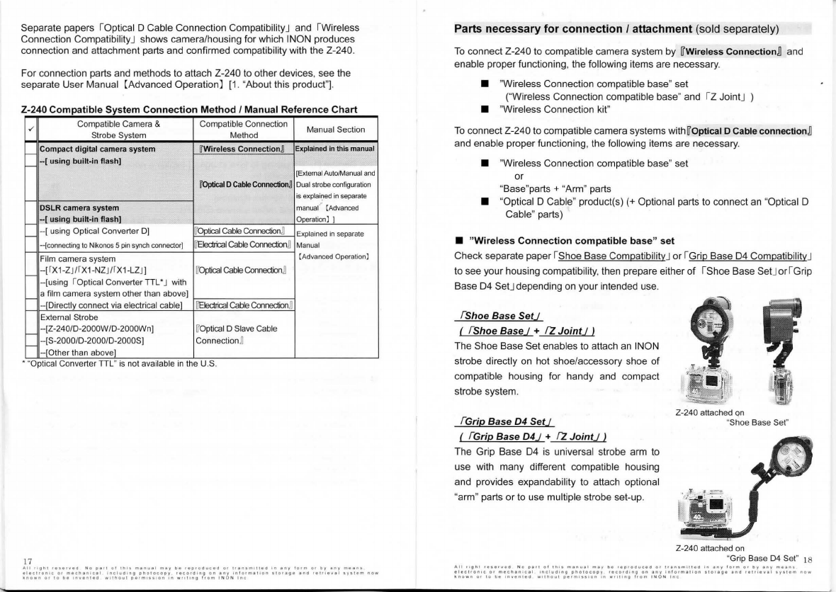
Separate papers IOptical D Cable Connection CompatibilityJ and
IWire
less
Connection CompatibilityJ shows camera/housing
lor
which INON produces
connection and attachment parts and confirmed compatibility with the Z-240.
For connection parts and methods to attach Z-240
to
other devices, see the
separate User Manual [Advanced Operationl [1. "About
th
is produci"].
Z-240
Comp
atible System
Connection
Me
thod
I
Ma
nual Reference Cha
rt
,,
Compatible Camera & Compatible Connection Manual Section
Strobe System Method
f-1
Compact digitai
ca
mera system UWireless
Conn
ect
i
o
n
~
Explain
ed
in
this
man
ual
f-1
- [ using built-in flash]
{Ext
erna1
Auto/Manual and
IT
O
ptical
DC
able
Co
nnectionJl
Dual strobe configuration
is explained
in
separate
DSLR
ca
mera system
manua
(
(Advanced
r-
-[
using bu
ilt
-in flash] Operation] ]
f--
-[
u
si
ng Optical Converter D]
lf0p
tica1
Cable
Connedion
n Explained in separate
--(connecting lo Nikonos 5 pin synch connector)
ITEledrica
1
eab1e
eonnection
n Manual
Film camera system [Advanced Ope
ra
tion]
f--
-[fX1-ZJ/fX
1-NZ
J/fX
1-LZJ]
IT
Opticai
Cable
Connection
n
-[using
IOptical
ConverterTIL"
J with
f-- a film camera system other than above]
-[Directly connect v
ia
electrical cab
le
] li'Eledrical
Cable
Connection
n
External Strobe
f-
--[Z-240/D-2000W/D-2000Wn]
IT
Optical D Slave Cable
f-
- [S-2000/D-2000/D-2000S] Connectionn
--[Other than above]
• "Optical Converter TTL" 1s not ava1lable
1n
the U.S.
17
"Il
•lghl
•••••v•O
No 11••1
o!
1hlt
"''""•I
"''Y
be
'"o•oOuced
or
t•
11n•rT1•1!•0
'"
'"'
101
m
or
bJ
anJ
means
elecuon1c
or
mlc~an•cel
1ncl1101ng
onolocopy
recordlng
on
eny
1n l
1>rme1ton
• •
ora11e
enO
retr<ev"I
•y1!em
now
known
01
10
oe
1nvent•O
w1tno
.. 1
o••m1••1on
'"
w"''"ll
!rom
I N
ON
lnc
Parts
necessary
for
connection
I
attachment
(sold separately}
To
connect Z-240
lo
compatible camera system by W
Wi
reless
Con
n
ec
ti
o n~
and
enable proper functioning, the following items are necessary.
• "Wireless Connection compatible base" set
("Wireless Connection compatible base" and rzJointJ
• "Wireless Connection kit"
To
connect Z-240 to compatible camera systems
withW
Optical D Cable
co
n nect
i
on
~
and enable proper functioning, the following items are necessary.
• "Wireless Connection compatible base" set
or
"Base"parts + "Arm" parts
• "Optical D Cable" product(s) (+Optional parts to connect
an
"Optical D
Cable" parts)
• "
Wireless
Connection
compat
ible base" set
Check separate paper IShoe Base CompatibilityJ or I Grip Base D4 CompatibilityJ
to see your housing compatibility, then prepare either of IShoe Base SetJorl Grip
Base
04
SetJ depending on your intended use.
{Shoe Base Se
t)
( {Shoe Base) +
rz
Join
tJ
I
The Shoe Base Set enables to attach
an
INON
strobe directly on hot shoe/accessory shoe of
compatible housing
lor
handy and compact
strobe system.
{
Gr
ip
Ba
se D4 Se
t)
( {
Grip
Base D4) +
rz
Join
tJ
I
The Grip Base
04
is
universal strobe arm t_o
use with many different compatible housing
and provides expandability to attach optional
"a
rm
" parts or
to
use multiple strobe set-up.
Z-240 attached on
"Shoe Base Set"
Z-240 attached on
"Grip Base
04
Set" t8
Ali
1111nr
•••••••O
No
1>•'1
ot
1n11
manu.i
may
111
•eprooucea
o•
'""""'il!ed
In
any
lo•m
o•
llJ
1ny
meen1
elect<on1c
or
m•chan1cal
1nclud1n11
11no1ocooy
•eco<d•"ll
on
any
1nformar1on
11a••11•
ano
re1t1eval
1y.iem
now
~no
w
n
or
10
oe
onvente<I
wHhout
111rm1111on
1n
'"''""Il
from
I N
ON
!ne
•wireless
Connection
Kit
Optional !Wireless Connection KiU is necessary when using
~
wireless
connection
~
for this produci to link to compatible camera system.
Please check separate paper IWireless Connection CompatibilityJ
if
your
underwater housing allows to use
~
wireless
co nn
ection
~
.
• "
Optical
D Cable"
product
(+optional
parts
to
connect
"
Optical
D
Cable
"
product
Specific "Optical D Cable" products are available for each camera system.
See the separate IOptical D Cable Connection Compatibi
li
tyJ and prepare
appropriate "Optical D Cable" produci and an optional pari to attach the "Optical D
Cable" produci (if necessary) for your housing.
• "Base" parts + "Arm" parts
Prepare both
of
"base" parts and "arm" parts for your particular undérwater
housing according to below chart.
"Optional Arm Set" is used together with "Necessary Arm Parts" to widen strobe
positioning for various subjects and shooting conditions, and to suit different
attachment lenses. See P.19 for actual examples.
lnon "arm" is a strobe arm to attach between "base" parts and the Z-240 to
suppor! ftexible
li
ghting for various subjects, shooting conditions or attachment
lens configurations. See next page for actual examples. We recommend starting
out with minimum set-up and then expand your arm system with the op
ti
onal "arm"
parts as necessary.
"
Base~rts
+
"
arm
"
~rts
com_E!ltibili!l_
,/
Camera
Mfr
,
Housing
Mo
del
"B
ase
"
parts
"A
rm
"
parts
Sy
s
tem
Compact
Genuine housing
GripBase
D4
d.!.9.!tal
camera
Digitai
SLR
Olympu
s
PT
-E
03
,
PT-E05
PT-E0
6 Ho
ld
er
Il
Set
or
DirectArm Z S
et
or
r--1
INON
Ho
lder
Il
·
Gr
ipSet
Arm
SS/S/M/L
Set
Z
X
-2
for
EOS
100 [
*J
X-2
for
EOS
200
X-2lor
EOS
300
X-2
for
EOS50D/40D
[
?.::
] See INON Arm
11
leaflet or INON web site for deta
rl.
19
11111
"11"1
••l••••d
No
P••1
ol
lh•I
m•nuel
m•y
be
•eprod
..
ced
o•
11e111m1
11
ed
'"
eny
lorm
o•
oy
any
mear
..
elec1ton1c
or
mec11an1cal
1ncludtflll
pholocopy
record1ng
on
any
1nlo<ma11on
1 \
o•ege
1nct
r1111evel
1y11em
now
~
nown
orto
be
1nven1e11
w11nout
perm1111on
"'
wfltong
"om
IN
O N
lnc
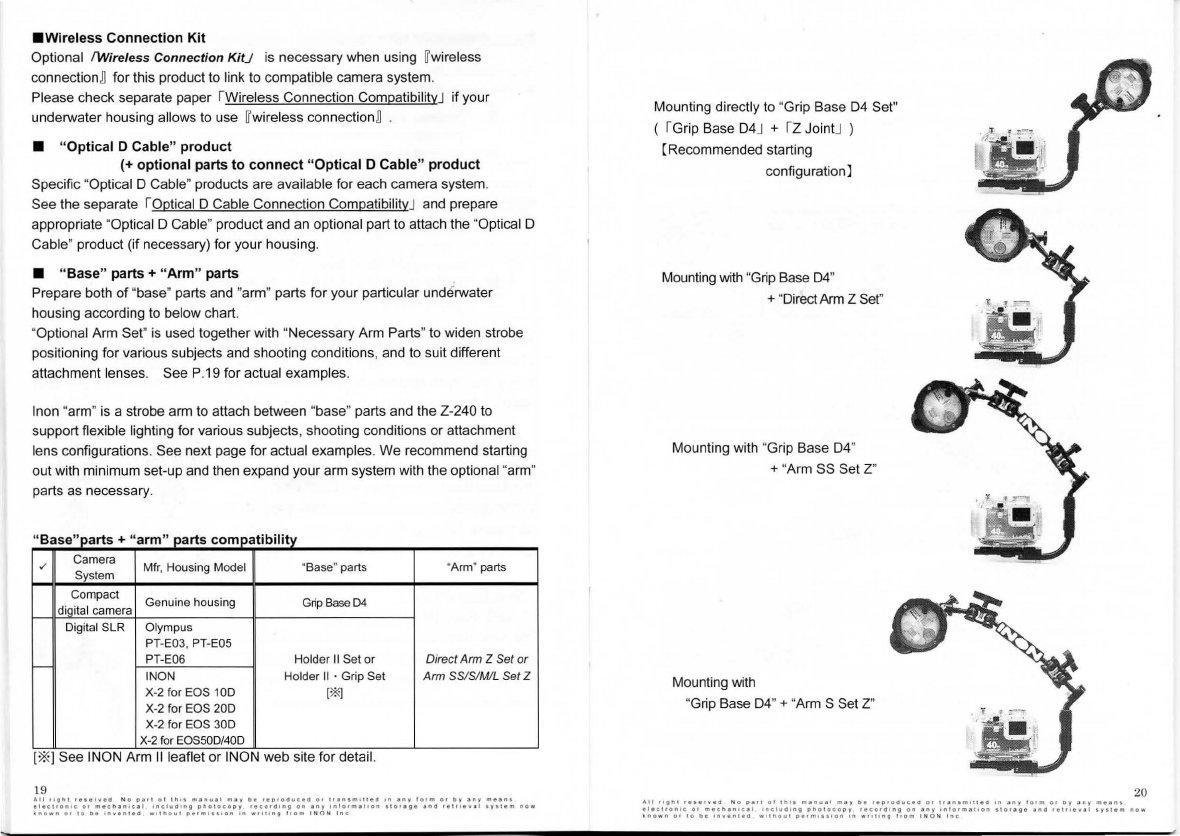
Mounting directly to "Grip Base
D4
Set"
(
IGrip
Base
D4
J + I Z JointJ )
(Recommended starting
configurationl
Mounting with "Grip Base
04
"
+ "DirectArm Z Set"
Mounting with "Grip Base
04
"
+ "Arm SS Set Z"
Mounting with
"Grip Base
D4
" + "Arm S Set Z" "
a;'
·'.
...
,
..
I
..
~
·
-
20
All
11gn1
••s••••ll
No
pali
ol
lhtf
menual
m;oy
oe
•eoroduceo
or
11en1m1ued
•n
any
lorm
or
1>y
env
mean1
elec•ro
nlc
O•
mechanu:al
1nclud1ng
olla1acopy
record1ng
on
any
1n101mat1on
Ho••&•
ano
1e111eval
•Y•lem
now
~nown
O•
lo
be
•n•enud
wil~oul
oe•m!•••on
1n
w1111ng
!
rom
INON
lnc
Z-240
compatible
"
AA
" batteries
Four "AA" battery types(li:i) can
be
us
ed w
ith
th
e Z-240, as
in
chart below.
After selecting what battery you will use, prepare tour batteries of same type,
same manufacturer and same model.
IN
ON
recommends using
fourIT
AA "eneloop" rechargeable battery (HR-3UTG)n
(0
0 )
Z-240
Compatible
Battery
Chart
Re
-c
harg
eable Type Characteristics
Noi
re
-chargeable
Re-chargeable
AA
"eneloop"Baaeries
[Recommended]
Eas~
to obtain
{HR-3UTG){l!!l!!J_
AA
Ni
MH
Batteries
I(1.2V][good
quality
ll_
l!!l!!
®_
(U
seabl
e)
Easy lo obtain
One
-
time
use
AAA
lkaline Batteries
{Useable)
E
asy
to obtain, low cost.
(
not
re-chargeab1e
)
(1
.S
V)
21
AA Uthium Batteries I[Useablel
c~~~:
t~~~;
~~~~~~~r;~ratures
.
(1
.
SV)
Extr
eme
l
Jjg_
htwei hLJP5% wei hl of Alkaline batteries
Some
AA
battery has bigger size comparing to conventional standa
rd
AA
battery to
carry higher capacity, which can not
be
used
lor
INON strobes.
So
far, Nexcell
offers this type
of
bigger size
of
AA
battery.
lncluding "
new
generation" NiMH batteries ("eneloop" type) having less
self-discharging and heat generating characteristic comparing to
"
co
nventiona
l
~
or
"high-capacity" NiMH, below listed NiMH batteries h
ave
been confirmed compat1ble
so
far as "
new
qeneration" NiMH batterv.
·
SA
NYO
Electric
Co
.,
Ltd
Model
nam
e : eneloop
[re
co
mmend
e
d]
Model code : HR
-3UTG
·
Sony
Corp.
Model
name
: Cycle Energy Blue
Model code : NH-AA-2
BKA
,
NH-
AA-4BKA
· Panasonic Corporatlon
Model n
ame
: Rechargeable Ni-MH (AA)
Model code : HHR-3MPS
· Maha Ene
rg
y
Co
rporation
Mode
l name : IMEDION
Model code :
MHRAAl4
·
GP
Batte
ri
es
lnternational Limited
Model name : ReCyko+
Model code :
210AAHCBE
·
ANSMANNAG
Model
name
:
max
E
Model code : 5030991 , 5030992, 5035052
· Electrochem Automation lnc.
Model
name
: NEXcell energyON
Model
code
: n/a (AA 2000mAh)
Some
~
conve
ntional
"
or "high-capacity" NiMH r
ec
hargeable batteri
es
have significant
self-discharge and heat-generating cha
ra
cte
ri
stic resulting difficulty to keep
th
eir
performance during usage.
We
r
eco
mmend using r
eco
mm
ended batteries.
Ali
rig
h l
r1t1rv11d
N o
PI"
ot
11111
man
.. 1 1
mar
01
11proa
u
ce<I
o<
tr1n1mlnea
•n
1ny
form
O•
by
eny
m1an1
1l1c1ronlc
01
m1c111nlc•I
1ncluct1ng
pno1ocopy
r1coro1ng
on
any
1n l
o1ma1lon
11or111•
and
r11rl1val
ay1
1
1m
now
~nown
or
IO
DI
ln•enle
O
w1ll\1tul
pe1m111IDn
1n
w•lr1n11
!rom
I N O N
lnc
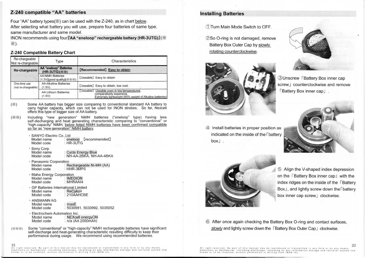
lnstalling
Batteries
G)
Turn Main Mode Switch to OFF.
~
So
O-ring is not damaged, remove
Battery Box Outer Cap by slow
ly
rotating counterclockwise.
@
Un
screw
IBattery
Bo
x inner cap
sc
re
wJ
counterclockwise and remove
IBattery Box inner
ca
pJ
@ lnsta
ll
batteries
in
proper position as
indicateci on
th
e inside of the
lbatte
ry
boxJ
@ Align
th
e V-shaped index depression
on
the IBattery Box inner capJ with
th
e
index ridges
on
the inside of
th
e I Battery
Bo
xJ
, and l
ig
htly screw down the lbatte
ry
box inner cap screwJ clockwise.
@ After once again checking the Battery Box O-ring and contaci surfaces,
slowlva
nd
lightly sc
re
w down
the
IBattery Box Outer CapJ clockwise.
22
All
"Il"
'
r111iveo
N o
pa!I
01
liii•
m•nu•I
may
oe
r1pro<1uc11a
or
1r1n1mi11
1 0
>n
•nr
lorm
or
Dy
any
m
o1
n1
el1cl•on1c
or
mechan1c1I
lr"ludlng
pllo1oce1
p y
recor01ng
on
ilny
1n
l
ormiltoon
llO•age
ano
r•lr+•v•I
•Y•l•m
now
~nown
or
10
be
111venl•O
w11110~1
perm1111on
on
w•!ling
hom
I N
ON
lnc
Alter
installing
batteries,
leave
Main
Mode
Switch
setto
OFF.
For
the
sake
of
safety
,
do
not
turn
ON
until
Optical
O
Cable
is
connected
or
wireless
connection
is
ready
to
use.
Whenever
opening
or
closingrBattery
Box
Outer
Cap
J,
always
check
battery
box
O-ring
and
O-
ring
contact
surfaces
tor
cracks
,
scratches,
contaminants
etc.,
and
maintain
as
necessary
.
See
P.
10
rMeasures
to
Prevent
Accidental
Flooding
"J
for
reference.
Make
sure
to
sufficiently
grease
the
O-ring
and
open/close
the
cap
slowly.
Otherwise
Battery
Box
O-ring
may
bind
or
twist
,
likely
causing
serious
water
leakaqe
.
Use
caution.
Do
not
use
manganese
or
non-specified
batteries
to
prevent
accident
andlor
damage..
Far
battery
precautions,
see
rsatety
Precautions
J
described
in
another
paper
, r 1.
Preparing
to
Take
lmages
--
Parts
necessary
fòr
connection
I
attachment
(P.17)J
and
rJ.
Alter
Taking
lmages
--
Regarding
Batteries
(P.
47)
J
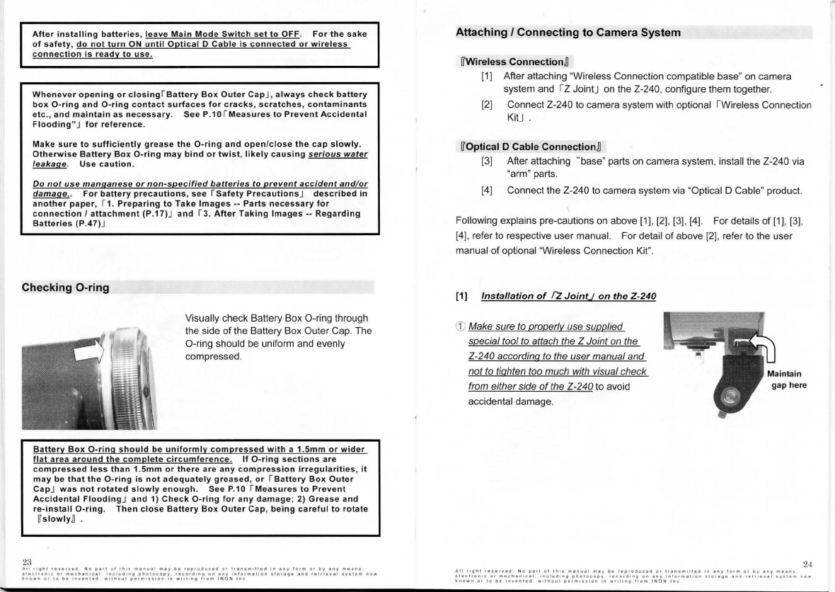
Checking
O-ring
23
Visually check Battery Box O-ring through
the side of the Battery Box Outer Cap. The
O-ring shou
ld
be uniform a
nd
eve
nl
y
compres
sed
.
Battery
Box
O-ring
should
be
uniformly
compressed
with
a 1.Smm
or
wider
flat
area
around
the
complete
circumference.
lf
O-ring
sections
are
c
ompressed
less
than
1.Smm
or
there
are
any
compression
irregularities,
it
may
be
that
the
O-ring
is
not
adequately
greased
,
or
r B
atte
ry
Box
Outer
Cap
J
was
not
rotated
slowly
enough.
See
P.10
rMeasures
to
Prevent
Accidental
Flooding
J
and
1)
Check
O-ring
for
any
damage
;
2)
Grease
and
re-install
O-ring
.
Then
close
Battery
Box
Outer
Cap
,
being
careful
to
rotate
h
lowly
D .
Al1
"IJhl
••••rv•a
Na
p•!1
or
lh'"
,,,.nu•I
may
b•
••pooauc•a
or
lf•n•m•ll•d
' "
any
!01m
o•
oy
any
m•a•u
•
l•ct•on1c
or
mecnan•c•I
1nclu<11ng
pho!ocopy
reco•d•nu
on
•ny
1nlorm•t•on
t!O••ll•
ana
••!•l•••I
•vatem
now
'nown
or
IO
Oe
•nvenl•d
w1thout
p11m1111on
'"
W
f!\lng
!rom
INO N
lnc
Attaching
I
Connecting
to
Camera System
~
Wireless
Connection
~
[1] After attaching "Wireless Connection compatible base"
on
camera
system and rz JointJ on the Z-240, configure them together.
[2] Connect Z-240
to
camera system with optional rwireless Connection
KitJ
~
Optical
D Cable
Connection
~
[3] After attaching '"base" parts
on
camera system, install the Z-240
via
"arm" parts.
[4] Connect the Z-240
to
camera system
via
"Optical D Cable" produci.
Following explains pre-cautions on above [1]. [2], [3]. [4]. Far details of [1], [3].
[4]. referto respective user manual. Far detail of above [2], r
eferto
the user
manual
of
optional "Wireless Connection Kit".
[1]
lnstallation
of
fl
JointJ
on
the
Z-240
(j)
Make sure
to
properlv use supplied
special tool to attach the Z Joint on the
Z-240 according
to
the usermanua/ and
not
to
tighten tao much with visual check
from eitherside
of
the Z-240
to
avoid
accidental damage.
24
IU!
11ght
••••r.•a
No
part
01
lh••
manual
m•y
b•
••111oaucea
or
t1•n1m111ea
1n
eny
!orm
01
oy
any
mean1
etectron•c
o•
mechan
lce
l 1..
c1ua1ng
photocopy
recoralng
on
•"Y
lnt<>rm•Hon
H0••11•
ena
re111eve1
•J•Um
now
known
o<
10
O•
1nv•n
1
ea
w
11
nou1
oerm1111on
'"
w'"'"ll
l•om
! N
ON
lnc

[2]
Connecting
to
the Z-240
by
!Wireless
Connection
kit
J
G)
To
use S-TTLAuto mode under
[3)
25
IT
Wireless Connection
],
IT
Camera
Camera
Mi
rror2
Mirror] ["Mirror Sticker (camera)" or
"Mirror Unii (camera
)"
(Camera
CameraMirror1
Mirror 1 or Camera Mirror 2)
included
in
optional I Wireless
Connection KitJ ]
is
necessary.
Check necessary
IT
Camera Mirror]
and preparation according to separate paper IWireless Connection
CompatibilityJ and attach the mirror as instructed
in
the user rnanual
of
the
IWireless Connection KitJ . "Clear Photo Film"
is
not usable for
IT
Wireless
Connection]
Methods
and
precaution
when
attaching
Z-240
to
"
Arm
"
parts
G) According to the user manual of each produci, prepare the specified
necessary screw/washer etc.
Caution: Not using the specified
screw
lwas
her
mav result in damaqe to
Z-240 strobe.
(g)
Slowly screw
in
clockwise,
making sure
it
does not contaci
the Z-240 body. Always make
sure there
is
a gap between the
end of the screw and strobe body.
f
Ma
= n
gap here
G) Confirm that the ISynch Connector CapJ
is put onto thelSynch ConnectorJ. lf not,
be
sure to put
it
in
piace in accordance
with the instructions below:
1) Referto IMeasures
to
Prevent
Accidental
Fl
ooding J on P.1O
of
this
manual [Basic Operationl and
conduci [inspection] and
[grease-up] of the O-ring, O-ring
grooves, and O-ring contacfsurface.
2) Piace the ISynch Connector CapJover the ISynch ConnectorJ.
En
sure thai
the cap
is
properly
al
ign
ed
(i.e
.,
straight),
and
then push
in
the
center pari.
3)
As the center pari
is
being pushed
in
, turn the screw pari clockwise, and
fully tighten
it
until
it
comes
to
a stop.
Caution: fai/ure to
push
al/ the way in
or
diaqonal threadinq
of
the
screw
may
result
in water /eakaqe
(g)
Check
you
r "Optical D Cable" parls
to
see if it
is
current
IT
Type U and its
ISensor Plug(strobe side cable connector)J
is
"wireless type" which
is
compatible with
th
e Z-240 [Type 4)
lf
yours
ISensor
PlugJ is "non-wireless type
",
it
is
necessary
to
replace
it
with
supplied Iwireless type Sensor PlugJ provided with
IT
Type L] "Optical D Cable"
products.
Refert
o the instruction manual ofthe "Optical D Cable" products for
detail of the replacement of the Sensor Plug.
lf you use non-"Type L" Optical D Cable products, some modification
is
necessary to use supplied Sensor Cap. Referto next page for detail of the
modification.
Current
~
Type
U "Optic
al
D Ca
bl
e'' products Non nype
L
~
"Optic
al
D Cable" products
Right: Wireless type - compatible -Not compatible
Left: Non-wireless type - Not compatible
26
Al!
"11111
rt•ttwe<I
N o
D•!l
ot
lh•a
m•n11•I
mty
bi
H•orod11c10
or
l!
e
nam111cd
1n
any
!orm
o•
by
any
"'''"'
t11c11onlc
o•
m•c"an•C•I
1nclu<11n11
photocopy
record•n'OI
on
'"Y
1
..
101me
!
lon
110••11'!
ano
"trlew•I
ays1em
1>ow
-
nown
or
10
be
1nwen11<1
w11hou1
oerml111on
•n
"''"'"Il
hom
I N O N
lnc

@
In
accordance with camera system
and
"Optical D Cable" user manual,
connect and fix Optical D Cable
ba
re fiber
end
to your camera system.
@ Piace Sensor Plug
end
of "Optical
D Cable" directly over !Slave
Sensor
J , lightly push
on
, and
screw down until lightly snug, but
not too tight.
When attaching and removinq, be
carefu/ not
to
exert excessive force
or
SensorPlug and/or Slave
Sensormav be damaged.
How
to
replace Sensor Plug
· Remove the E-ring (metal retaining ring) !rom
bottom pari of supplied ISensor CapJ
by
a screw
driver etc.
as
shown
in
righi image
Sensor
Plug
~
· We use the pari ( ISensor Plug · WirelessJ )
indicateci by the arrow
in
the left image. Make
sure not to loose other component parls
· With a precision screw driver, loosen screws of
your IOptical D CableJ products to remove
pre-installed non-wireless type Sensor Plug
then attach the ISensor Plug · WirelessJ
· Hold inside ofthe ISensor Plug · WirelessJ with
your finger
to
keep aligned screw holes and
tighten screws completely
to
fasten
on
the
IOptical D CableJ products •
Whenever
attaching/removing
to/from
Z-240 and camera
system
,
always
make
sure
both
camera
svstem
power
and
Z-240 Main
Mode
Switch
are
setto
OFF.
27
Ali
rog
hi
r•••r.•a
No o a r 1
or
1
n1s
manu11
m:ay
be
1ep1oduç1d
or
1ran•m
ll
!IHI
1n
1ny
lotm
or
by
:any
meant
el1cl•on1c
or
mech1>n•cll
1nclud1ng
pholocopy
recora1n11
on
any
ln
!
1>rm111on
s!o11ge
and
1e111ev1I
sysum
now
-
nown
or
10
De
lnven
!ed
wllhoul
perm1111on
'"
w"l"'ll
! •
om
l'ION
lnc
Configuring Z-240 with pre-flash type camera
and shooting
in
S-TTLAuto.
Quick
&
Eas
Auto
Ima
(S-TTL)
Basic Light Adjustment Methods
...
..
........................................ 29
Limitation
on
Focus Light continuous mode and flashing .......
30
Shooting with S-T
TLAut
o Exposure
..
..............
...
.............
..
........... ........
31
Adjusting Strobe Output
in
S-TTLAuto ... 37
28
All
•lg
ht
•etl<Yld
No p e
ti
a l l
hll
m•nu•I
may
be
•ep•C>duced
or
111n1m111ea
on
eny
lorm
or
Dy
any
m"'"'
1!1cnon1c
o r
mocnanlc•I
1nc!11clln11
oho1o
copy
••co<cllnll
on
any
1n !
orm•l•On
1to•age
""a
••tfl&v•
I
1y11em
now
~nown
or
lo
be
onvenlecl
Wllhoul
oetm111
lon
In
w11 1
1ng
l<om
I N O N
lnc
Basic
Light
Adjustment
Methods
Z-240 has many available functions, compatible with:
· 4 types of camera/strobe systems
· 5 connection methods
· 5 ftash output adjustment methods
1) S-
TIL
Auto mode
2) External
Au
to mode
3)
TI
LAuto mode
4) Manual + TTL Auto mode
5) Manual mode
This section explains how
to
configure compact digitai camera system I DSLR
camera system (emits built-in flash like INON X-2) and shoot in simple and easy
W
S-TI
L AutoJ mode. (shaded region of a chart
in
next oaqe)
•
S-TI
L
Au
to mode
S-TTLAuto
is
INON unique exposure control method to suppor! hig
hl
y
accurate yet easy strobe shooting. S-TTLAuto basically provides fu
ll
y
automatic exposure control based on informati
on
from camera system.
Al
most any diçiital camera supported
by
WWireless
Conn
e
ct
i
on
~
or WOptical
DCable
Conne
cti
on
~
is
compatible with S-TTLAuto mode (0 ).
Also the Z-240 connected to S-TT
LAuto
operating INON strobe
by
W
Op
tical
DSlave
Connectio
n~
, works in S-TTLAuto mode.
(0 ) A digitai camera making total
2
~
3
fl
ashes
(1
~
2
pre-ftash + 1 main
ftash) and confirmed compatible
by
INON.
S-TI
LAuto compatible camera/housing are listed in separate paper rMaster
Strobe (digitai camera built-in fiash) Group Char!J Listed camera/housing has
dedicateci accessories lo connect and install INON strobe,
so
INON confir
ms
~
S-T
T
L
AutoB compatibility as whole of camera system.
For using other strobe control modes, and connection methods other !han
WOptical D Cable connectionB I WWireless connectionB , including setting and
preparation, see separate user manual [ (Advanced Operation) 1. About This
Produci].
29
All
r1gn1
•••••••"
No
p•H
ol
1n11
m•nu•I
m•r
1>•
reprottue.ed
01
l••,.•mluoo
111
any
1orm
"'
by
any
maant
ete~t1on1c
or
mec1u11.,c.i
1ncl11d•n11
p1101ocoor
•ecora1n11
on
eny
•nl1Hme11on
olorage
and
relnew•I
•r•Um
now
~nown
orto
be
11iwe11ua
w1lllo111
perm••••Oll
1n
wri!lng
trom
tNON
lnc
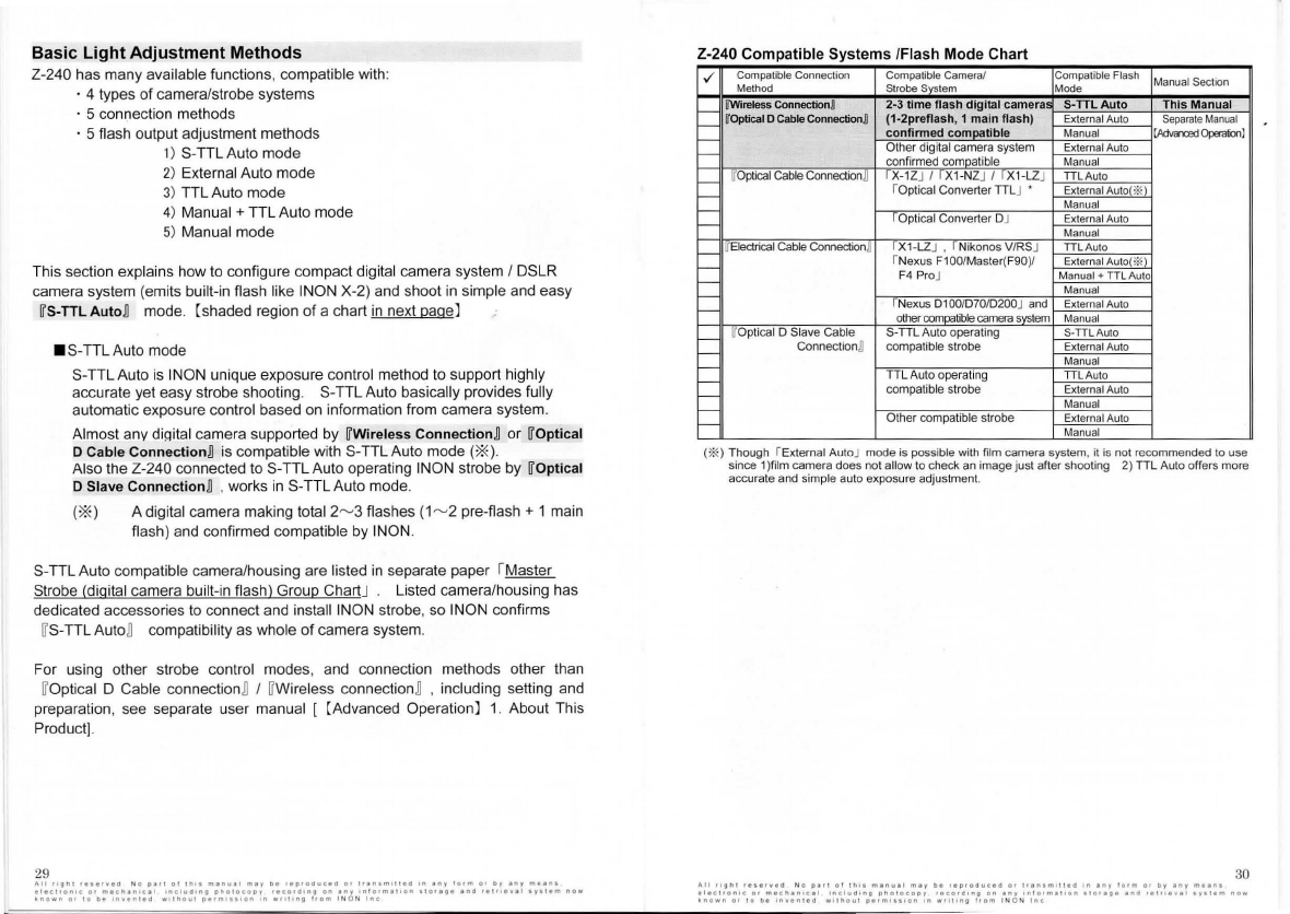
Z-240
Compatible
Systems
/Flash Mode Chart
./
Co
mpatible
Co
nn
ection Compatible Camera/ Compalible Flash Manual Section
Melhod
S
t
robe
~
e
m
Mode
1--
ù'Wireless
Connectionn 2
·3
t
ime
flash
d
igitai
cameriiSI
S·TTLAuto
This Manual
1--
~
Optica
l
o Cable
Connec1ion
n
(1-2prenash
, 1
main
flash)
External Auto
Separate
Manual
r--
c
on
fi
nTi
ed
com~ible
M
an
ual
[Mvarced~)
r--
Other digitai camera system External Auto
confirmed
co
~t
ib
l
e
Manu
al
1--
~
Op
tica
l
Cable ConnectionD r x -1ZJ I r x
t-N
ZJ I r x 1-LZJ
TIL
Au
to
r--
rOptical
Co
nverter TTLJ • ExternatAuto(*
_l_
r--
Manual
ÌOptic
al
Co
nv
erter DJ
Ex
ternal Auto
r--
Ma
nual
1--
WElectri
ca
l Gabk! ConnectionD rx t -LZJ , f Nikonos V/RSJ TTLAuto
fNexus F100/Master(
F9
0)/
Ext
e
rn
alAut
o<
*
.l
r--
F4 ProJ Manual +
TTL
Auto
r--
Manual
1--
rNexus 0 1OO/D70/D200J and External Au
to
1--
other
co
~bk!
ca
mera
~
e
m
Manual
r--
l[
Optical D Slave Cable
S-TIL
Auto operating S
-TTL
Auto
1--
Conn
ec
tion] compatible strobe External Au
to
Ma
nu
al
1--
TIL
Auto operating
TTLA
uto
r--
r--
co
mp
atible strobe Extern
al
Auto
Manual
r--
Oth
er
compatible s
tr
obe External Auto
1--
Manu
al
(* ) Though rExternal AutoJ mode is possible
wi
th film camera system, it is
no
t rcco
mm
ended to use
si
nce 1)film camera does not allow to check an image just after shooting 2)
TIL
Auto o
ff
ers more
accurate a
nd
simple auto exposure adjustment.
30
,t,11 11g11t
res•,.•CI
No
par!
ol
Il"•
m•n11•I
may
b•
••1>roauc•C1
or
t••nlml\\ed
'"
any
lo•m
or
1>y
;ony
m1an1
•l•c1
•
1>n1c
o•
m•chan1cal
1ncluaong
pnotocopy
••cordong
on
any
•nlo•ma
!
oon
01<111ge
and
••P••••I
•yt11m
now
~n
own
orto
bi
lnve"lld
wotllOu\
pt1mo101on
In
WfH•ng
!rom
I N O N
lnc
Limitation
on
Focus
Light
continuous
mode
and
flashing
•Focus
Light
continuous
mode
limitation
The Focus Light should NOT continuously turn ON more than 30 minutes and
make sure
lo
cool down its LED
unii
and inner electrical circuii by turning OFF
the Focus Liqht at least 1Ominutes .
For maximum battery life, the Focus Light should be turned ON only when
necessary
lo
minimize heat generation and battery drain.
•
Limitation
on
repeated
flashes
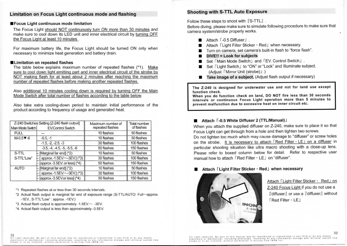
The table bel
ow
explains maximum number
of
repeated flashes
(*1
).
Make
sure
lo
cool down light emitting part and inner electrical circuii
of
the strobe by
NOT makinq flash
lor
at least about 2 minutes alter reaching the maximum
number
of
repeated flashes before making another repeated flashes.
Also additional 1
O minutes cooling down is reguired by turning OFF the Main
Mode Switch alter tota! number
of
flashes according to the table below.
Also take extra cooling-down period to maintain initial performance
of
the
produci according to frequency
of
usage and generated heat.
Z-240
Switches
Setting
[Z
-2
40
fla
sh
output]
Maximum number
of
Total
number
Main
Mode
&Mtd1
E
V.Co
ntrol
Switch
repeated
fla
shes
offlashes
FULL
-10flash
es
50flashes
M-0.5
1'
-6 -0
.
5,
,, 10flashes 50flashes
-1
.5,-
2,
-2.5
,
-3
30
flashes
100
flashe
s
-3
.5,4 ,
4.5
,
-5
,
-5.5
,
-6
50flashes
150flashes
S-TIL
[Marginai
far
end]
(•2)
10
flashes
50flashes
S.TTL"Low
" [
approx
.
- 1
.5
EV.
~
-3EV.
]
(*3)
30
flashes
100flashes
[
approx
.
-3
.
5EV
.orl
ess]
r4)
50flashes
150fl
as
h
es
AUTO
[Marginai
far
end]
(*2)
10flashes
50flashes
[
approx
.
-1
.
5EV.~3EV.]
r3)
30
flash
es
100flashes
[appro
x.
-3
.
5EV.or
less]
(*4)
50flashes
150flashes
'1
Repeated
flashes
al
or
less
than
30
seco
nd
s
interv
als
.
•2
Actual
flash
output
is
marginai
far
end
of
expos
ur
e ra
ng
e
(S-
TIU
AU
TO
:
Full
~
approx
.
-1EV
.,
S-TIL"
Lo
w
":
approx
.-
1E
V.)
•3
Actual
fla
sh
output
is
ap
p
roximate
l
y-
1
.5
E
V.
~
-3EV.
•4
Actua
l
flash
outp
ut
is
less
than
approximately
-3
.
5EV
.
Shooting
with
S-TTL
Auto
Exposure
Follow these steps to shoot with
IT
S-TTU
Before diving, please make sure to simulate following procedure to make sure thai
camera system/strobe properly works.
• Attach r-0.5 DiffuserJ
• Attach ILight Filter Sticker · RedJ when necessary.
• Turn on camera, set camera's built-in flash to "force flash
".
• DIVE!! =
Look
for
subjects
• Set IMain Mode SwitchJ and r
EV.
Contro! SwitchJ
• Set ILight SwitchJ to "ON"
or
"Lock" and Illuminate subject.
(Adjust IMirror Unii (strobe)J )
• Take
image
of
a
subject.
(Adjust flash output
if
necessary)
The
Z-240
is
designed
tor
underwater
use
and
not
far
land
use
except
function
check.
Wh
en you do function check
on
land,
DO
NOT
fire less !han
30
seconds
intervals
or
continuous
Focus
Light
operation
more
than
5
minutes
to
prevent
malfunction
due
to
excessive
h
eat
on
inner
circuit
etc
.
•
Attach
1-0.5
White
Diffuser
2
(TTUManual)J
When you attach the supplied diffuser on Z-240, make sure to piace it so thai
Fo
cus Light can gel through from a hole and then tighten two screws.
Do not tighten too much which may cause damage
lo
"diffuser" or screw holes
on the strobe.
lt
is necessarv
lo
attach
IRed
Filter · LEJ
on
a diffuser
in
particular shooting situation like ultra macro shooting with a close-up lens.
Please refer to boxed column below
lor
detail. Refer to respective user
manual how to attach rRed Filter · LEJ
on
"diffuser'
'.
•
Attach
ILight
Filter
Sticker
• RedJ
when
necessary
Attach r
ught
Filter Sticker · RedJ
on
Z-240 Focus Light
if
you do not use a
IT
diffuser
~
or use a
IT
diffuser
~
without
IRed Filter · LEJ
32

33
::\<i
Il
is
not necessary
to
use
rne
d Filter ·
LE
B and
~
Light
Filter Sticker ·
Red
B
together. Either of them will previde necessary effect. Refer
lo
the box
column
in
this page lor detail of function
of
the filter and when
you
need
them.
Since
Z-240
has
higher
power
, it is
likely
to
have
overexposed
image
when
using
a
digitai
camera
equipping
ordinary
metering
performance
on its
built-in
strobe
(does
noi
allow
lo
make
small
flash)
under
particular
shooting
situation
below
;
e
correct
exposure
can
be
obtained
with
ambient
natural
light
e
macro
shooting
with
open
aperture
The
overexposing
can be
prevented
in
most
case
by
attaching
r
-0
.5
Whte
Diffuser
2
(TTL/Manual)J
which
also
helps
to
widen
flash
beam
angle
from
1oo·
lo
11
o·
and
soften
light
quality.
So
generally
we
recommend
to
attachr-o
.5
Diffuser
2 Jon
Z-240
except
you
encounter
insufficient
flash
light
.
Please
refer
lo
P. 42
of
separate
manual
[
[Advanced
Operation]
1.
About
This
Produci
-
Z-240
Name
of
Parts
-19.
-0.5
White
Diffuser
2(TTL/Manual)]
lor
detail
of
supplied
"
diffuser
".
The
r
Red
Filler
·
LEJ
and
rLight
Filter
Sticker
·
RedJ
has
two
main
funclions.
[Function
1]
Helps
noi
lo
scare
away
shy
subjects.
[Function
2)
Enables
more
accurate
~
S-TTL
n
Auto
Exposure
by
minimizing
influence
of
Focus
Light
on
camera
's
automatic
exposure
calculation
in
ultra
macro
shooting.
Roughly
,
ultra
macro
shooting
with
shooting
distance
less
than
5cm/2in.(less
than
10cm/4in.
belween
strobe
and
subject)
in
[
S-TTL
n
auto
mode
without
using
rRed
Filter
·
LEJ
I
rught
Filter
Sticker
·
RedJ
may
result
underexposure
.
For
strobe
control
modes
other
than
[
S-TTU
,
il
does
noi
matter
il
the
rRed
Filter
· LEJ I
rFilter
Sticker
·
RedJ
is
attached
or
noi.
So
first
take
a
shot
without
the
filter/sticker
and
attach
it
if
you
need
benefits
of
the
filter/sticker
described
above.
Please
see
P.42
of
separate
manual
[
(Advanced
Operation]
1.
About
This
Produci
--
Z-240
Name
of
Parls
-20.
Red
Filter
·
LE/30.
Light
Filter
Sticker
·
Redl
lor
detail.
Ali
119n1
•eser.•O
No
1>••1
ol
1n+ •
many.i
m;q
De
reproauce<t
o•
transmltied
In
any
torm
or
by
any
mean•
•l•c1ronlc
or
m•chan•cal
•nclu01n9
phoTocopy
••cora1ng
on
anr
1n
torm
ar
lon
•
1c<a
ge
a
no
re\•lev
a l
•Y•1'1m
now
b1own
or
10
De
lnvenreo
w11nou1
permiss1on
In
w1111ng
!rom
I N O N
lnc
• Turn
on
camera,
set
camera's flash
to
"
force
flash
"
Set the camera's built-in strobe flash mode lo "farce flash
".
Do
noi
set "red eye reduction"
to
ON.
Some camera models only allow "Force Flash"
in
some shooting modes. (For
example, with some Canon models "farce flash"
is
not possible except
in
~
M
modeB
".)Se
t your camera
lo
a shooting mode which allows "farce flash".
Also,
in
a separate menu, some cameras allow setting the "red eye reduction"
feature. Make
su
re
this function
is
setto
~
OFF
B
Referto your camera instruction manual lor details.
With
cameras
thai
permit,
set
the
"ALL
RESET"
feature
lo
OFF
,
so
thai
even
after
you
turn
the
camera
power
off
,
the
built-in
strobe
settings
you
choose
will
remain
and
not
be
cleared.
For
example
,
with
some
Olympus
cameras,
in
[
Mode
Menu
n
'set
"ALL
RESET"
to
[
OFF
n .
• DIVEll
=Look
for
.
subjects
Working
temperature
range
is [0°
C-30
°C/ 32°F.......,86°F](water
temperature)
EV(+;..)
Controller
A B C
O,.---·--.......O
(
/
"\
-0.5
M
.,
- 6
FUL
First set IEV Contrai
SWitchJ
lo
[ Bn ,
then
setlMain
Mode SwitchJ
to[STIU
00
11
may be preferable to set rMain Mode
SwitchJ I rEV Contr
ai
SwitchJ
other
than
[
STTU/
[ Bn depending
on
camera system
(especia
ll
y when using point and shoot
compact digitai camera tor beginners
).
See
next page
lor
detail.
Swilching
the
Main
Mode
Switch
lo
any
position
except
[
OFF
n
will
turn
on
Z-240
power
,
indicated
by
rstrobe
Ready
Light
J
shining
red
.
34

• Set
ILight
SwitchJ
to
"ON"
or
"Lock"
and
illuminate
subject.
(Adjust
IMirror
Unit
(strobe)J
position)
Adjust strobe aiming
lo
illuminate subject with
Focus Light, by
~
pressing
Light Switçh onceB
for (Single Mode) or
~
pushing
and turning
to
"Lock" B
lor
(Continuous Mode).
To
ensure
Z-240
proper
performance
il
is
important
to
properly
aim
Z-240
at
a
subject.
Be
sure
to
confirm
strobe
aiming.
Also
"
Focus
Light
"
assists
and
quickens
camera's
auto
focusin
Q
so
you
can
obtain
better
images.
With
Focus
Light
set
lo
"
Continuou
s
Mode
"
the
light
will
automatically
shut
off
in
sync
with
camera's
preflash
,
and
then
automatically
turn
on
again
0.5
seconds
later
.
Therefore
,
far
shutter
speed
longer
than
0.5
seconds,
light
of
Focus
Light
may
be
exposed
in
the
image.
In
this
case,
set
Focus
Light
to
"
Single
Mode
" .
When using
~
Wireless
ConnectionB , "Mirror Unii (strobe)" musi
be
adjusted
according
to
the strobe position. For detail, reler
to
IWireless Connection
KitJ
user manual.
lt
is
essential
to
aim
the
strobe
to
a
su
bject
properly
and
point
the
r
Mirror
Unit
(strobe)J
to
the
"Mi
rror
Unit
(camera)"
to
ensure
proper
op
erati
on
and
enhance
5-TTL
accuracy
.
Make
sure
lo
adjust
the
Mirror
Unii
(strobe)
properly
whenever
you
change
strobe
position
.
35
All
<19111
••••rv
•O
No
P•tl
ot
11111
ma11<1a1
may
t>e
reproouceo
o•
11a1umllte<I
'"
any
lorm
or
"'
an~
means
a1ectron1c
or
mec"antCll
•nCl<1!11"g
ono1ocooy
reco•Oong
on
•ny
onform•Hon
1
10119
1
•nd
relrleval
1y111m
now
~nown
or
10
01
1nven1111
w11no111
011m,..,on
'"''"''""Il
l<om
!N
O N
lnc
Il
is
recommended
lo
turn
[OND
the
Z-240
righi
before
shooting
and
turn
il
[
OFF
D
soon
alter
shooting
when
you
use
[
Wireless
Connection
D .
The
Slave
Sensor
of
the
Z-240
is
ultra
sensitive
and
could
be
triggered
by
other
strobe,
ambient
light
like
reflecting
sunlight
on
the
surface.
• Take image
of
subject
. (Adjust flash output
il
necessary.)
Take the image with not exceeding liimitation on number
ol
continuous
repeated strobe llashesJ described
in
previous section/separate paper
to
avoid
heating /degradation
ol
light emitting part or inner electri
ca
l circuii. Check the
monitor to see
il
image
is
properly exposed.
In
most cases
no
lurther
ad
ju
stment
is
ne
cessary. However, lor some camera models and shooting
conditions it may be necessary to adjust setting
ol
Z-240.
~
For
actual
adjustment
method, see
next
page.
The
flash
precision
of
[
S-TTL
Auto
n
is
basically
the
same
as
the
camera
's
built-in
strobe.
lf
the
camera
's
basic
flash
precision
is
poor
,
or
the
camera's
underwater
flash
precision
is
low
,
full
auto
exposure
control
may
be
d
iffi
cult
,
and
il
may
be
necessary
to
adjust
according
lo
the
shooting
conditions
.
For
details
see
next
page
.
Ple
ase
check
following
3
points
tirsi
before
you
go
lo
next
section,
if
you
ob
s
erve
[too
brighi
(overexposed)
I
too
dark
(underexposed)]
image(s)
by
5-TTL
Auto
mode+
[
Wireless
Connection
D .
1)
Check
if
the
"
Mirror
Unii
(strobe)
"
is
properly
adjusted.
2)
Check
if
the
"
Camera
Mirror
"
is
properly
attached.
3)
Check
if
there
is
any
obstacle
between
the
"
Mirror
Unii
(strobe)
"
and
the
"
Camera
Mirror
"
(it
could
be
your
finger!)
.
Ref
er
to
optional
r
wireless
Connection
Kit
J
user
manual
tor
detail.
36
All"ll"
••
•••
•
veO
N
op•f1ol1n11m1nu
a
lm
a
ybereor1>0<1c100•1t1n1m1
11
eo1n1ny
lo•mo•
t1yen1mflan1
1lec1ron1c
01
m1cn1n1cal
oncluO•ng
pno
c
oco
o y
rfrcordong
on
1ny
1nlorma11on
sto••g•
ano
••l,.eval
sya11m
now
~nown
or
10
oe
1nven11<1
••lftoul
oe•m•asoon
'"
w"llng
l•om
INON
l
nc
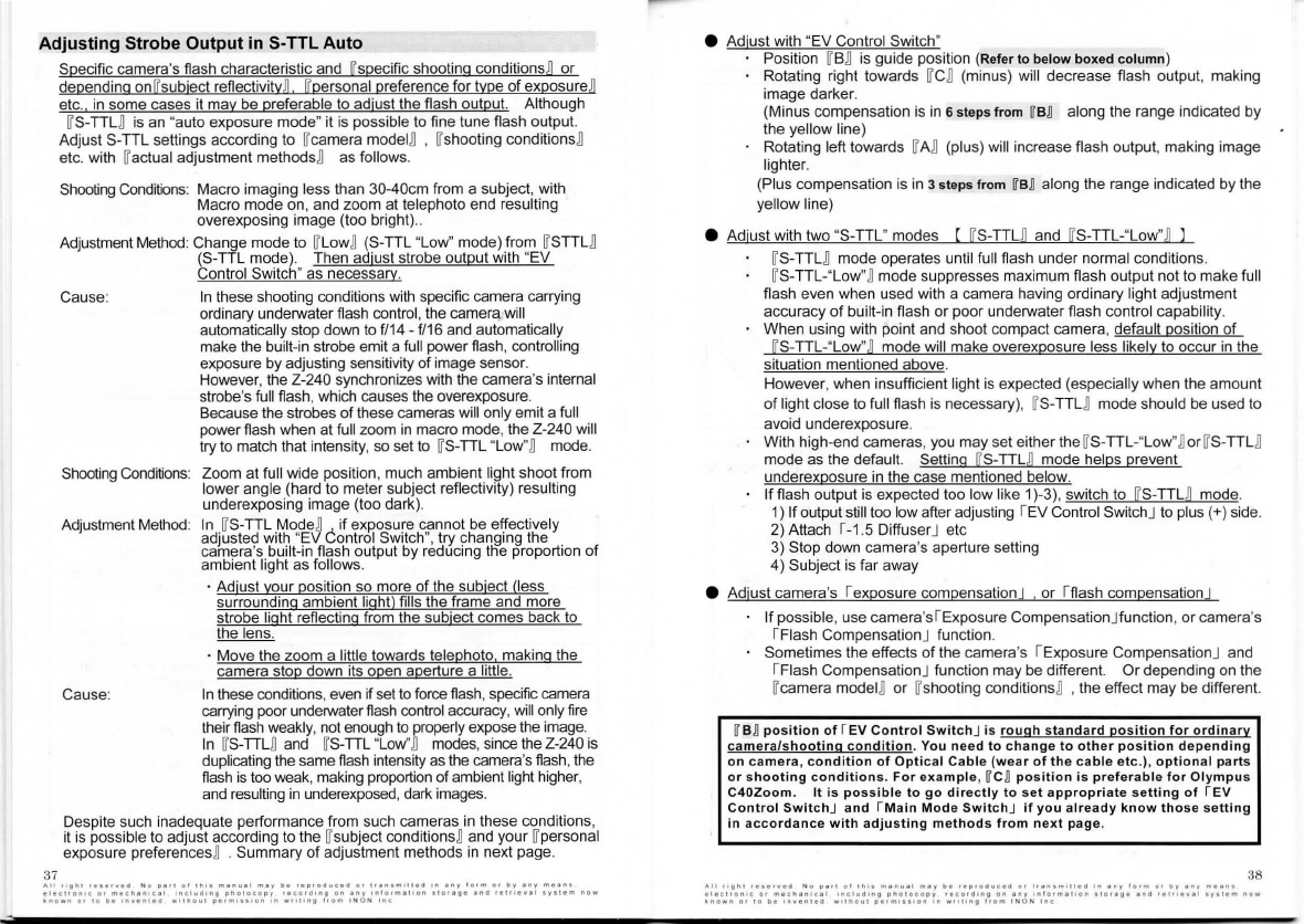
Adjusting Strobe Output
in
S-TTL Auto
37
Specific camera's flash characteristic and [specific shooting conditionsB or
depending on[ subject reflectivityD [personal preference tor type
of
exposureB
etc.
in
some cases it may be preferable to ad
ju
st the flash output. Although
WS-TTU is an "auto exposure mode" i! is possible to fine !une flash output.
Adjust S-TTL settings according
!o
Wcamera modelB , Wshooting conditionsB
etc. with Wactual adjustment methodsB as follows.
Shooting Conditions: Macro imaging less !han 30-40cm from a subject, with
Macro mode
on
, and zoom a! telephoto end resulting
overexposing image (too brighi)
..
Adjustment Method: Change mode
!o
WL
ow
B (S-TTL "Low" mode) from WSTTU
(S-TTL mode). Then ad
ju
st strobe output with "EV
Control Switch" as necessary.
Cause:
Shooting Conditions:
Adjustment Method:
Cause:
In
these shooting conditions with specific camera carrying
ordinary underwater flash control, the camera.wi
ll
automatically stop down to f/14 - f/
16
and automatica
ll
y
make the buil!-in strobe emit a full power flash, controlling
exposure by adjusting sensitivity
of
image sensor.
However, the Z-240 synchronizes with the camera's internal
strobe's full flash, which causes the overexposure.
Because the strobes
of
th
ese cameras w
ill
only emit a full
power flash when at full zoom
in
macro mode, the Z-240 w
ill
try !o match thai intensity, so
setto
WS-TTL "Low"B mode.
Zoom at full wide position, much ambient light shoot from
lower angle (hard to meter subject reflectivity) resulting
underexposing image (too dark).
In
WS-TTL ModeB if exposure cannot be effectively
adjusted with "EV èontrol Switch
",
try changing the
came
ra
's built-in flash output by reducing tlìe proportion
of
ambient light as follows.
· Adjust your position so more
of
th
e subject (less
surrounding ambient light) fills the frame and more
strobe light reflecting from the subject comes back to
the lens.
· Move the zoom a
Jittle
towards telephoto makinq the
camera stop down its open aperture a little.
In
these conditions,even if setto torce flash, specific camera
carrying poor underwater flash control accuracy,
wìll
only lire
their flash weakly, no! enough
to
properly expose the image.
In
WS-TTU and WS-TTL "Low"B modes, since the Z-240
is
dup
li
cating the same flash intensity
as
the camera's flash,the
flash
is
too
weak, making proportion ofambient light higher,
and resulting
in
underexposed, dark images.
Despite such inadequate performance from such cameras
in
these conditions,
i! is possible to adjust according to the Wsubject conditionsBand your Wpersonal
exposure preferencesB . Summary
of
adjustment methods
in
next page.
All
.,
111
1'11
r••••v•O
N o
P••I
o!
1n11
m1nu11
m1y
oe
reproduceo
or
11
e
n1m11teo
'"
1ny
!orm
or
oy
any
meen•
elec1ron1c
or
mecn1n1c11
1ncludt
1>Q
pno
1
ocopy
rocc,,a1ng
on
any
1n
l
o1me11on
1101111•
anot
rel,..,val
1yst•m
now
\nown
or
10
oe
1n,.en1ea
w11no1u
11e•m111•on
'"
w
rlllng
trom
I N O N
lnc
e Adjust with "EV Control Switch"
Position WBB is guide position (Referto below boxed column)
Rotating righi towards WCB(minus) will decrease flash output, making
image darker.
(Minus compensation is
in
6steps trom WBR along the range indicated by
the ye
ll
ow
line)
Rotating left towards WAB (plus) will increase flash output, making image
lighter.
(Plus compensati
on
is
in
3steps
from
WBRalong the range indicated by the
yellow line)
e Adjust with two "S-TTL" modes ( [ S-TTU and [ S-TTL-"L
ow
"D l
WS-TTU mode operates until full
fl
ash under normai conditions.
WS-TTL-"Low"Bmode suppresses maximum flash output no! to make
fu
ll
flash even when used with a camera having ordinary light adjustment
accuracy
of
built-in flash or poor underwater flash control capability.
When using with point and shoot compact camera, default position
of
[S-TTL-"Low
"n
mode will make overexposure less
li
kely to occur
in
the
situation mentioned above.
However, when insufficient light is expected (especially when the amount
of
light close to full flash is necessary), WS-TTU mode should be used to
avoid underexposure.
With high-end cameras, you may set either the WS-TTL-"L
ow
"BorWS-TTU
mode as the default. Settinq [S-TTU mode helps prevent
underexposure
in
the case mentioned below.
lf
flash
ou
tput
is
expected too low like 1)-3), switch to [
S-TTU
mode.
1)
lf
output stili too low after adjusting IEV Contro! SwitchJ to plus (+) side.
2) Attach
1-1
.5 DiffuserJ etc
3) Stop down camera's aperture setting
4) Subject is far away
e Adjust camera's rexposure compensation I , or ltlash compensa
ti
onJ
lf
possible, use camera'sl Exposu
re
CompensationJfunction,
or
camera's
!Flash CompensationJ function.
Sometimes the effects
of
the camera's I Exposure CompensationJ and
I Flash CompensationJ function may be different.
Or
depending
on
the
Wcamera modelB or Wshooting conditionsB ,
th
e effect may be different.
WBRposition
of
f
EV
Control SwitchJ is rough standard position
tor
ordinary
camera/shooting
condition.
You
need
to
change
to
other
position
depending
on
camera
,
condition
of
Optical
Cable
(wear
of
the
cable
etc.),
optional
parts
or shooting conditions. For example, WCRposition is preferable
tor
Olympus
C40Zoom.
Il
is possible
lo
go directly
lo
set appropriate setting
of
f
EV
Control SwitchJ and fMain Mode SwitchJ
if
you already know those setting
in
accordance
with
adjusting
methods
from
next
page.
38
All
righ
i
r••••V•d
No
o•fl
ol
!h
ls
m•11u•1
m•y
be
rep•oduced
01
1t•n1m•1t•d
•n
•"Y
lo1m
o•
Oy
•"Y
me•nt
e •
ecironlc
or
mech•n!cal
includlng
pno1ocoo1
•ecord1ng
on
eny
ln
lormali
on
1 1
01•11•
and
1e111evel
1y11em
now
~nown
or
10
O•
'
""'"l
tlt:I
w.inoul
aerm1111on
on
w"ling
l
<om
I N O N l
nc
Other manuals for Z-240
1
Table of contents
Other INON Camera Accessories manuals


Popular Camera Accessories manuals by other brands


Trojan
Trojan GC2 48V quick start guide

Calumet
Calumet 7100 Series CK7114 operating instructions

Ropox
Ropox 4Single Series User manual and installation instructions

Cambo
Cambo Wide DS Digital Series Main operating instructions

Samsung
Samsung SHG-120 Specification sheet

Ryobi
Ryobi BPL-1820 Owner's operating manual