INON Z-240 User manual
Z-240
Type4
User Manual
(Advanced Operation)
Optical Connection (advanced)
Electrical Connection
Be sure that you have read and understood "Safety Precautions"
described
in
another paper before using Z-240.
This English Manual
is
provided only for INON approved export products.
This product carries official customer support (technical support, warranty
service and repair/overhaul)
by
I
NON
authorized distributors/dealers or by
INON
In
c.
via
INON authorized distributors/dealers. Please contact your INON
authorized distributor/dealer w
hen
you need customer support.
Features
no
t mentioned
in
this manual are explained
in
separate Use Manual
[Basic Operation]. Before reading this manual, complete understanding and
familiarization with contents of [Basic Manual]
is
essentially recommended.

Manual Organization
This Manual (Advanced Operation]
is
organized
as
follows.
To
ensure proper use, before using please read "About this product"
(P.4)
to
thoroughly confi
rm
the product's features and limitations with
each camera system.
1
2
3
4
l
About
this
product
(P.4-43)
Explanation
of
Z-240 features, parts and
configuring with camera systems.
Preparation (ExtemalAuto/Manual/TIL) (P.44-55)
Explanation
of
preparation for External Auto I
Manual I TTL mode.
Using the Z-240 (P.56-71)
Explanation
of
operating method for each Z-240
control.
Reference (P.72-83)
Specifications, options, support.
A l l
1111111
re•••Yld
N o
o••
1
or
tllil
m1n.,1I
may
1>1
reproduc1a
or
u
an1mr
u e o '
"a
ny
l
o•
m
Of
by
a n y m 1 a111
el1c1ronlc
or
m1cll1n1c
a t
lncl11dr11g
pllo
t
ocopy
r1cor
d
•ng
on
any
1nlorm111on
510
•1
!11
a
nd
1
1\r
l
eval
1y111m
now
~nown
or
ID
be
•llYllllld
wlllloul
pe1mu1
10
11
111
wrltong
lrorn
IN
O N
Inc
Contents
Manual Organization
Contents
..
............
..
..
......... 1
············· 2
1 About this product....................................4
Z-240 Main Functions
..
............................
...
5
"S-
TIL
Auto" Flash Mode 5
Slave Strobe Function("S-
TIL
Auto
"/
"External Auto" Flash Modes) ......... 5
Wireless Slave Function (wireless "
S-TIL
Auto"
Fl
ash Mode)
.. ..
5
Flash Function ("TTL Auto
"/
"External Auto" Flash Modes) ......... 6
Shutter Linked Auto-Of! Focus Light.. .....
...
....... ... .
...
6
Clear Photo System Compatible .................... ..................... ......... 6
Advanced Cancel Circuitry
..
..... 7
"Manual + TTL Auto" Flash Mode ............................................................. 7
Reference
(j)
rAutomatic
Fl
ash Adjustment
of
External StrobesJ . ...
....
8
Reference
~
rn TLJ - What is it?J .........................................................
10
Reference @
rW
Pre-flashJ - What is it?J ..................
10
Reference @ r"External Auto" (External Automatic
Flash Exposure Adjustment)J ............ 10
Reference @
rw
s-TI
U What is it?J
.....
......
11
Reference @
rW
Master Strobej and WSlave Strobe
JJ
........
..
11
Reference
<J)
rAdvanced Cancel CircuitJ ................................................ 12
Reference @ rc1ear Photo SystemJ
..
. 12
Reference ® r WManual +
TIL
AutoJ What is it? J................................. t3
Connecting Z-240 to Camera System ............................ ...........
14
Optical D Cable Connection ................. ...........
14
Wireless Connection ................. ..........................
14
Optical Cable Connection .. ................................................................. 15
Electrical Cable Connection
..
.. ....... 15
Optical D Slave Cable Connection ..............................
..
............ 16
Items to confirm before using Z-240 ................................... .
..
18
Confirming how to use the Z-240 .....................................................
..
..... 18
Confirming camera system I master strobe I housing
..
............
18
Confirming useable functions . ........ 22
Confirming attachment method
..
............. 26
Connection example
in
dual strobe configuration ............................. 27
Reference
(j])
rHandy multi strobe set-up with WExternal AutoJ I WManualJ
and WWireless
Conenction
~
J ...................... 35
Description
of
Parts & Controls ....
...
. ......... .
..
36
2
All
ng111
•••e•veG
N o
part
of
""'
man111I
rn•y
bl
repro<1uc10
or
111111m1
11
eo
111
any
l
otm
or
Dy
any
m11ns
eleclronoc
o•
mecl!•nlc•I
1ncl11d1n11
pl!o
l
ocopy
reco1d1n11
on
•
ny
on l
o•m•llon
HOr•ge
•nd
relrleve!
system
no
.,
~
n
own
o•
10
b"
l
n••ntod
w111!0111
po<mi•tlon
1n
wr
i
ting
!tom
I N O N I
nc

2 Preparation....
...
........
...
...........................44
Before starting preparation ...........................
..
....
..
..
..
............................. ......... 45
Camera System Preparation .... 46
When using with connecting to digital camera's built-in strobe ..... 46
Using with
IN
ON Optical Connection compatible camera syste
ms
..
. 48
Using another external stro
be
as a slave strobe ...................................... 48
When using the
El
ectrical Connection with the camera system. . ..... 49
Strobe Preparation . ..............................................
..
...
......................
52
Setting Advanced Cancel Circuit ........................................ .
...
...
...
52
Setting Main Mode Switch I E
V.
Control Switch and
+1/4EV. Compensation Switch .................................................... ......
..
...
55
3 Using the Z-240......................................
56
Main Mode Switch Setting Method
...
.....
..
..
57
Focus
Li
ght Switch use
···
·············· ...............
..
...
59
How
to
use Advanced Cancel Circuit Switch ......................
..
...........
.
....
..
..
..
. 60
E
V.
Control Switch,
+1
/4E
V.
Compensation Switch use .......
61
External Auto shooting tips
..
. ............................................................
..
....
..
. .
..
65
Reference @ rExposure when using strobesJ ..
.....
............................. 69
Reference ® fDifferences between using external strobes
with digital cameras and film camerasJ
...
..... 70
Reference @ rCharacteristics of External Auto Exposure
Adjustment systemsJ ......... 70
Setting flash output
in
Manual mode and
maximum flash output
in
Manual +TTLAuto mode .............
71
4 Reference ......................................
...
....
72
Accessories (Sold separately) ..........
..
..... . 73
Specifications ............................................................... ..................... ............. 77
After Service ...................
..
............................................................................ 78
After Service
...
...................
..
.................. ............... 79
3
Al
l
t!Qhl
t11o
er."d
N O
pa<l
ol
!hi
•
m•nuel
ma
y
be
reproduced
or
! f a
no
m l
l!
e d
in
a n y t
orm
Ot
b y
•n
y m
ean1
.
eteclfo
n1c
or
me
chanica
l
1nclud1ng
pnatocooy
teco<d•ng
on
any
•n
l
o1mat
1
on
s 1
01age
and
1e
11
1e •
al
s
yo
1
em
now
~nown
o<
10
he
,n.
ented
w'1nout
pe11
ni
o
•1on
'"
w111
..
1g
!
ram
IN
O N
Inc
Explanation
of
Z-240 features to confirm before
taking images.
1 About this product
Manual Organization .................
....
...
............ ..................
...
..
.....
....
.
..
................1
Z-240 Main
Fun
ctions ................
..
... ·············
····
················ .................. 5
Connecting Z-240 to Camera System ...... ....
..
... ..................
14
Items
to
confi
rm
before using Z-240 ............
..
.... ............... 18
Confirming how to use the Z-240 ...........................................
..
.............
..
18
Confirming camera system I master strobe I housing ................. 18
Confirming useable functions
..
.
...
......... .... ........
...
.
..
.....
..
..
..
.
...
..
..
.....22
Confirming attachment method ........................................
..
... .................. 26
Connection example
in
dual strobe configuration ..............
..
.........
......
..... 27
Description of Parts & Controls
..
... ...
.....
...
.
.....................
...
...
..
...
..
....
..
...
.
36
All
rt
9n1
reserveo
N o
pan
of
1
n1s
m11nua1
may
'
"'
1eproauceo
or
1r
an
1
m111ea
In
any
lorm
01
ay
any
m
eans
eleclfon1c
or
mechanica
l
<nclud1ng
photocopy
recoro1ng
on
any
1n
f
ormat•on
s1orege
and
1e1,.eve
l
1y11em
now
~
nown
or
10
~
-
onvented
w l
lh
o
ul
p•rmo
sslon
'"
wrl1
lng
from
! N O N
Inc

Z-240 Main
Functions
The Z-240
is
designed and manufactured
to
be
a high perfo
rm
ance, multi-function
underwater strobe with features such as "S-TTL Auto
",
"wireless connection"
capability without using a fiber optics, high-intensity power LED underwater light
providing 1801umen/20° coxerage, "Manual + TTL Auto" mode and several others
explained in summary below.
"S-TTL
Auto
"
Flash
Mode
By optically connecting to pre-flash type digital cameras (with
an
"Optical D
Cable" or by "
wi
reless co
nn
ection"), the Z-240 enables
to
shoot
in
"TTL Auto
exposure" supporting a wide range of cameras, regardless of make or
model. The Z-240 carries more sensitive slave sensor comparing
to
existing models enabling highly accurate exposure control.
Slave Strobe Function("
S-TTL
Auto"I "ExternalAuto" Flash Modes)
When connected
to
another (master) strobe, the Z-240 flashes
in
synch with
the master strobe. Connecting to compact digital camera is also employ
slave system to camera's built-in strobe (master strobe).
When connecting to pre-flash type camera, the Z-240 itself automa
ti
ca
ll
y
adjusts for proper exposure
in
IS-TTL AutoJ mode. Other slave flash
modes are !External AutoJ mode, which does not need a strobe control
signal from
th
e camera, and IManualJ mode with 13 adjustable steps of
flash output control.
Wireless Slave
Function
(wireless "S-TTL
Auto
" Flash Mode)
The Z-240 has ultra sensitive slave sensor
to
receive master strobe flash
light without "fiber optics" to support handy wireless slave strobe set-up with
compatible strobe arm. Under wireless circumstance with pre-flash type
digital camera, either of IS-TTL AutoJmode where strobe controls exposure
as like ''TTL Auto
",
I External AutoJ mode where the Z-240 controls flash
output by itself without camera's control orlManualJmode
to
provide 13 step
manual flash adjustment,
is
usable
All
<l11h1
••••r•ld
No
Pit!
of
lh11
m1n.,1!
ma,
b1
"'P•o<luceo
or
1ransm1111d
1n
1ny
torm
0 1
by
any
m
11
n s
elecnonlc
O•
"'ech1n1c11
<nclud1ng
p h
olocopy
reco•dln11
on
any
1n
! o
1m.i1on
sto••111
1
na
re1fl
ev•I
•v•tam
now
~no•n
o•
1o
be
1nve
nt1d
w11ho11t
11erm11s1on
"'
w1111n11 f
rom
IN
O N
Inc
Flash
Function
("TTL
Auto
" I "
External
Auto"
Flash
Modes)
When
ca
mera shutter
is
released the Z-240 flashes proper amount of light
in
synch with the camera system. Nikonos 5 pin type synch connector enables
"electrical cable
11
connection in addition to existing "optical connection".
When using with compatible camera systems the Z-240 operates
in
"Nikonos"
type ITTLAutoJmode common
in
conventional film camera systems, !Manual
+ TTLAutoJ mode combined system of advantages ofTTLAuto and Manual
mode, !External AutoJ mode, which does not need a strobe control signal
from the camera and IManualJ mode with 13 adjustable steps of flash output
contro
l.
Shutter
Linked
Auto-Off
Focus
Light'
The Focus Light has two main functions. First it shines light on the subject,
in
creasing reflectivity/contrast so both Manual and Auto Focusing are easier.
Also, it helps aim the strobe's beam axis
on
or
near the subject.
Th
e Focus
Light uses Cree high-intensity power LED (XR-E "Q5") which
is
useable as
independent diving light providing
1801m
and 20° coverage. Upon activating
the Focus Light Switch, the Focus
Li
ght
wi
ll
tu
rn
on, and upon sensing the
camera's internal strobe flash,
wi
ll
automatica
ll
y turn off so no light from the
Focus Light
is
recorded
in
the image2. Also the Focus Light can
be
set to turn
off automatically
in
about eight seconds if the Focus Light Switch is not pressed
again.
Clear
Photo
Svstem
Compatible
"Clear Photo System" allows the external strobe (Z-240) to
be
more effectively
used as a Slave Strobe, and enables cleaner, higher quality images by
reducing
th
e amount of backscatter3 caused by light coming from the camera's
built-in stro
be
illuminating suspended particles
in
front of the lens.
Clear Photo System was designed into the Z-240. "Clear Photo Film
",
included with INON "Optical D Cable/Cap Set" available for various cameras I
housing systems, enables Z-240 utilize Clear Photo System by connecting
IN
ON
Optical D Cable/Cap Set4.
1
Fo
r act
ua
l operation method, refer to r
3.
Us
in
g the Z-240 - Focus Light Switch use (P.61)J .
2 When shooti
ng
with shutter speeds slower than 0.5 seconds, the Focus Light
ma
y be recorded
in
the
image. Also, with some camera systems the Focus Light may be
re
corded in the image.
~ee
r3.
U
si
ng
th
e Z-240 -
Fo
cus Light Sw
it
ch u
se
(P.61)Jandr 1. About This Pro
du
ct -
It
ems to
co
nfirm before
us
ing
Z-240 -Confirming usable functions (P.23)J for reference.
3 Small
pa
rticles
su
spended
in
water be
tw
een lens and subject. which if illuminated by strobe, re
fl
ect
into
th
e lens and appear as
wh
ite specs or "snow".
4 Compatible only
wi
th
~
O
p
ti
c
al
D Ca
bl
e Connectionn . Not usable for
~
Wir
e
l
ess
Co
nn
ec
ti
onn .

Advanced
Cancel
Ci
rcu
i
try
Used when Z-240 connected
to
pre-fl
ash
type digital cameras, and shooting
in
I External AutoJ or IManua
lJ
modes. A special
ci
rcu
it
in
th
e Z-240 which
utilizes the pre-flash type camera's light adjustment principles
to
suppress the
camera's main ftash with following benefits:
• Shortens camera's internal strobe recycle time, allowing quicker
• fo
ll
ow-up shots. •
Reduces
ca
mera's battery consumption,
so
more images can be taken
per set of batteries.
Advanced Cancel Circuit
ry
turns OFF
in
IS-
TTL Auto J mode. which
reproduces the pre-ftash camera's fl
ash
adjustment method ITTL Auto J
mode and !
Manual+
TTL
Au
t
oJ
mode.
"
Manual+
TTL
Auto
"
Flash
Mode
"Manual + TTL Auto"
is
a function that
can
significantly avoid overexposu
re
caused
by
TTL er
ro
r or inappropriate
Ma
n
ua
l setting
by
a
ll
owing maximum
flash output of the TTL Auto mode
to
be set manually. "Manual +TTL Auto"
is
available
fo
r TTL Au
to
compatible camera/camera syst
em
under "Electrical
Cable" connection.
Referen
ce
G) r
Autom
atic
F
las
h
Ad
justme
nt
of External St
rob
esJ
When using external strobes,
in
order to automatically adjust the amount
of
flash output
and properly expose the subject, it is necessary to calculate and control the strobe's flash
duration (light output amount) using the following information.
• ISO sensitivity
• Aperture value
• Reflectivity
of
the subject
Of
this information, depending on the method
of
measurement and part
of
the subject
being measured for reflectivity, the methods of automatic flash output adjustment can
be
classified as follows:
1. During exposure the camera meters {measures) in real time
• Subject reflectivity measured
TIL
(Through The camera's Lens)
in
real time: strobe
quenches (turns off) at time of "proper" exposure.
(Real
Tim
e
TIL
Au
to
Ex
po
s
ur
e Adju
st
ment)
• Using a light sensor on the camera. subject reflectivity
is
measured
in
real time;
strobe quenches at time of
~p
rope
r"
exposure.
(Real Time
Auto
Ex
po
su
re
Adju
stme
nt)
2. Before exposure camera meters (measures) a "pre-flash"
• Camera's internal strobe fires a small
~
pre-fla
sh
n
to illuminate the subject. During
pre-flash, subject reflectivity measured
TI
L; based
on
this information. second (main)
flash duration
is
calculated, and then strobe fires main flash quickly afterwards, only
for the calculated duration. (Pre-flash
TIL
Au
to E
xp
os
ur
e
Adju
s
tm
ent)
3. During exposure strobe itself measures in real time
• Using a light sensor in the strobe, subject reflectivity measured
in
real time, with
strobe quenching at time of "proper" exposure.
(E
xte
rn
al Au
to
Flash E
xp
osure Adjustme
nt
)
For each of these automatic flash adjustment methods to work, besides a signal
instructing the external strobe to fire, following information is necessary. Also the
various combinations
of
cameras (and master strobes) and external strobes must be
compatible with each other's signal transmission methods and have connection method.
-In case of 1) above: Camera -External Strobe Instruction to stop flash
-In case
of
2) above: Camera -External Strobe Instruction to stop flash or
Instruction for flash duration
External Strobe -Camera External strobe information
-In case of 3) above: Camera -External Strobe ISO Sensitivity information, and
Aperture value information
As of April 2009, the majority
of
consumer digital cameras use r Pre-f
las
h
TIL
Auto
Ex
po
s
ur
e
Adju
s
tm
e
nt
J Unlike conventional 35mm film camera systems with the
widely adopted I Real
Time
TTL
Auto
Fl
ash
Adju
s
tm
e
nt
J , most current digital cameras
cannot use such automatic exposure adjustment with external strobes designed for Real
Time
TIL
(such as SB-105, YS-120 etc.). Likewise, except for some dedicated land
strobes for certain camera brands, there are no external strobes yet available fully
compatible
of
functioning with the various r
Pr
e-
fl
as
h
TIL
Auto
E
xpos
ur
e Adju
stme
ntJ
type cameras available.
8
All
,.11111
re•••Y•a
N o
paf1
or
th
••
man1111
may
be
•ep•od11cea
o r
1r1n•m1L1ed
111
any
1arm
o•
by
eny
mean•
elec1<on1c
or
mecn1n1c1I
l11cludl
n g p
hotocopy
11cord1
n g
on
any
1n1orm111on
s101age
and
r1tr1evll
•y.iam
now
•
nown
01
10
bl
!n•e
n
ted
w1
1
no11t
p11ml•11on
1n
wri11n11
from
I N O N I
nc
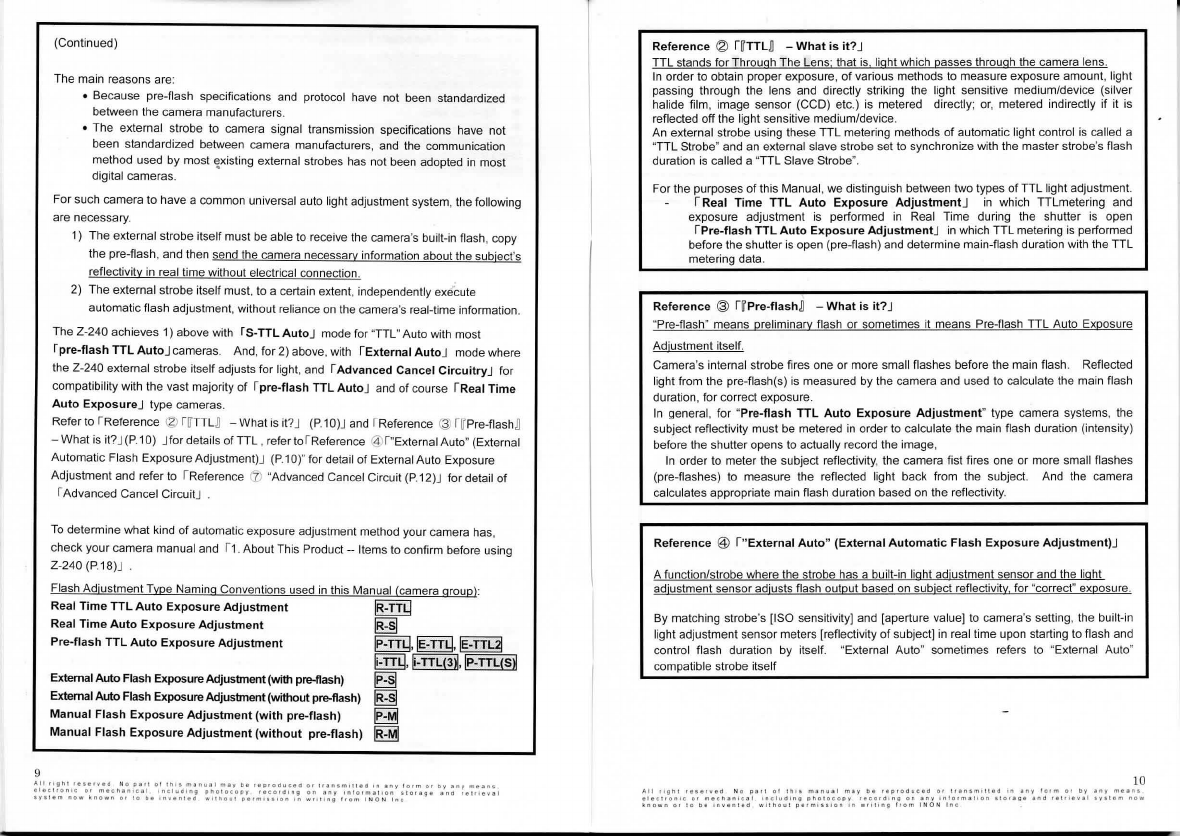
(Continued)
The main reasons are:
• Because pre-flash specifications and protocol have not been standardized
between the camera manufacturers.
• The external strobe to camera signal transmission specifications have not
been standardized between camera manufacturers, and the communication
method used by most
~xist
ing
external strobes has not been adopted in most
digital cameras.
For such camera to have a common
un
iversal auto
li
ght adjustment system, the
fo
ll
owing
are necessary.
1) The external strobe itself must be able to receive the camera's built-in flash, copy
the pre-flash, and then send the camera necessary
in
formation about the subject's
reflectivity in real time without electrical connection.
2) The external strobe itself must, to a certain extent, independently
exe"cu
te
automatic flash adjustment, without reliance
on
the camera's real-time information.
The Z-240 achieves 1) above with
fS-TTL
AutoJ
mode for "TTL"Auto with most
f
pre-flash
TTL
Auto
J cameras. And, for 2) above, with IExternal
Auto
J mode where
the Z-240 external strobe itself adjusts for light, and f
Advanced
Cancel
Circuitry
J for
compatibility with the vast majority
of
r pre-flash TTL
Auto
J and of course
fReal
Time
Auto
Exposure
J type cameras.
Refer to !Reference @
rn
TL
D - What
is
it?J
(P
.1
O)
J and !Reference
~
f~
Pre-flash
D
-What is it?J(P.10) Jfor details of TTL , refer !ofReference @ f "External Aut
o"
(External
Automatic Flash Exposure Adjustment)J
(P
.1
O)
" for detail of External Auto Exposure
Adjustment and refer to fReference "Advanced Cancel Circuit (P.12)J for detail of
f Advanced Cancel CircuitJ
To
determine what kind of automatic exposure adjustment method your camera has,
check your camera manual and r1.About This Product
--
It
ems to confirm before using
Z-240 (P.18)J
Flash Ad
ju
stment Type Naming Conventions used
in
this Manual (camera group):
Real
Time
TTL
Auto
Exposur
e
Adjustment
IR-TTQ
Real
Time
Auto
Exposure
Adjustment
Pre-flash
TTL
Auto
Exposure
Adjustment
External Auto Flash Exposure Adjustment(with pre-flash)
External Auto Flash Exposure Adjustment(without pre-flash)
Manual
Flash
Exposure
Adjustment
(with
pre-flash)
Manual
Flash
Exposure
Adjustment
(without
pre-Hash)
~
IP
-TTQ, IE-TTQ,
IE-TTL~
li-TTQ,
l
i-
TTL(3~
,
IP-TTL(S~
~
~
~
~
Reference @ f
IT
TTLD -
What
is
it?
J
TTL stands for Throuah The Lens that 1s light which passes through the camera lens.
In
order to obtain proper exposure,
of
various methods to measure exposure amount, light
passing through the lens and directly striking the light sensiti
ve
medium/device (silver
halide film,
im
age sensor (CCD) etc.)
is
metered directly; or, metered indirectly if it
is
reflected off the
li
ght sensitive medium/device.
An external strobe using these TTL metering methods of automatic light control
is
called a
"TTL Strobe" and
an
exte
rn
al slave strobe set to synchronize with the master strobe's fla
sh
duration
is
ca
ll
ed a "TTL Slave Strobe
".
For the purposes
of
this Manual, we distinguish between two types
of
TTL light adjustment.
f Real
Time
TTL
Auto
Exposure
Adjustment
J
in
wh
i
ch
TTLmetering and
exposure adjustment
is
performed
in
Real Time during the shutter is open
f
Pre-flash
TTL
Auto
Exposure
Adjustment
J
in
which TTL metering
is
performed
before the shutter
is
open (pre-flash) and determine main-flash duration with the TTL
metering data.
Reference @
fIT
Pre-ftashD -
What
is
it?
J
"Pre-flash" means preliminary flash or sometimes
it
means Pre-flash TTL Auto Exposure
Ad
ju
stment itself.
Camera's internal strobe fires one or more sma
ll
flashes before the main flash. Reflected
li
ght from the pre-flash(s) is measured by the camera and used to calculate the main flash
duration, for correct exposure.
In general, for "
Pre-flash
TTL
Auto
Exposure
Adjustment
" type camera systems, the
subject reflectivity must be metered
in
o
rd
er
to calculate the main flash duration (intensity)
before the shutter opens to actua
ll
y record the image,
In
order to meter the subject reflectivity, the camera fist fires one or more small flashes
(pre-flashes) to measure the reflected
li
ght back from the subject. And the camera
cal
cu
lates approp
ri
ate main f
la
sh
duration based
on
th
e reflectivity.
Reference @
["External
Auto
"
(External
Automatic
Flash
Exposure
Adjustment)
J
A function/strobe where
th
e strobe has a built-in light adjustment sensor and the light
adjustment sensor
ad
ju
sts flash output based
on
subject reflectivity
fo
r "correct" exposure.
By matching strobe's [ISO sensitivity) and [aperture value) to came
ra
's setti
ng
, the built-in
light adjustment sensor meters [reflectivity of subject]
in
real time upon starting to flash and
control flash duration by itself. "External Auto" sometimes refers to "External Auto"
compatible strobe itself
10
All
t1g
h1
re1erveo
N o p
ar!
o r t
h••
m•nu•I
""Y
lie
reptoauce11
ot
H•n1m11ua
I n
any
farm
or
lly
any
mean\
11ee\1onoe
or
meenano
c
al
•n
cludlng
phclo
cc
p y
••co
1a
lng
on
any
ln
!
orm
al
•on
Horag
e
an
d '
•l•
le
val
•
Y•tem
now
known
ot
lo
be
ln
v""'"O
wlthoul
pa
1
m111lon
In
w
"1ong
lr
om
INON
In
c

11
Reference @
rIT
S-TTLn
What
is
it?
J
S-TTL
is
an abbreviation
of
Optical Synchro
TTL
INON unique automatic light control system
in
INON Z-240 strobe providing "TTL Auto
Flash" with pre-flash TTL Auto type cameras by transmitting flash/quench information from
strobe
to
camera
via
an optical signal
in
stead of a camera maker specific elect
ri
cal signal
and
electrical
cord
.
Reference @ r
IT
Master
Stroben and
IT
Slave Strobe
nJ
"Master"
and
"Slave" are
terms
corresponding
to
"
which
strobe
is
the
contro
lling
device"
and
"
which
strobe
is
be
i
ng
controlled
".
When using two strobes (including the case
of
the camera's internal strobe
and
the Z-240),
where both the camera's strobe and Z-
240
are directly connected
to
the camera/housing,
and
are
control
l
ed
by
the
same
signal
.
since
there
is
no
difference
in
function
,
there
is
no
distinction
between Master
and
Slave.
However,
it
is
possible
to
connect
only
one
of
the
strobes
directly
to
the
camera/hous
ing
,
with
the o
th
er strobe connected
to
the first strobe.
The
strobe connected
to
the
camera/housing (Master) receives control signals directly from the camera and flashes.
At that time, the other (Slave) strobe is activated by the master strobe's flash.
"Master" and "Slave" terms are used when the two strobes have such definite master/slave
relationship.
This user manual uses following connection method terminology depending
on
master
strobe type.
IT
Optical D
Cable
Connection
~
Master strobe
is
camera's built-
in
flash.
IT
Optical D Slave Cable Connectionn Master strobe is
an
external strobe.
Reference
(J)
r
Advanced
Cancel
Circuit
J
Uti
li
zing the light control theory of pre-flash TTL Auto type digital cameras, compared
to
conventional strobes with a simple pre-flash cancel circuit which cause the camera's
internal strobe
to
emit a full discharge
on
the second, main flash, the Z-240 Advanced
Cancel C
ir
cuit effectively reduces the camera's main flash which shortens internal strobe
recycle time
fo
r faster follow-up shots and reduces camera battery consumption
so
more
images can be taken per set of batteries.
IT
External Auld mode and
IT
"Manualn mode can utilize Advanced Cancel Circuitry.
IT
S-TI
L Auton mode reproduces camera's pre-flash and pre-flash non-compatible
IT
TTL
Auton mode I
IT
Manual
+TTL
Auton mode does not require the Advanced Cancel Circuitry
and automatically turns OFF.
Reference @ rc1ear Photo SystemJ
A system where Z-240 flash control uses infrared light, not visible light. Attaching a
IT
Clear Photo Filtern , which
is
included with all INON Optical D Cable/Cap Set,
to
the
camera's internal strobe a
llo
ws
just the infrared light signal pass,
whi
ch
is
then transmitted
by fiber optic to the strobe. The result
is
reliable and consistent external strobe slave
flash, and suppression of backscatter, resulting
in
clearer better mages.
C:~:D
Currently, rs-2000J , rz-240J , r
o-2ooow
J , r o-2000WnJ , r o-2000J , rD-2000SJ
rD
-180J , rD-180SJ , I Z-220J ,
IZ
-220SJ and IZ-220FJ strobes have been tested and
confirmed compatible with this system.
For actual details of using this system and
its
benefits, see user manual included
with
Optical
D Cable/Cap
Set
Type L for
you
r camera system/Clear Photo System.
(lli)
Compatible only with
IT
Optical D Cable Connectionn .
Not usable for
IT
Wireless Connectionn

Refe
renc
e @ r
IT
Manu
a
l+
TTL
Auto
n
Wh
at
is
it? J
"Manual +
TT
L Auto"
is
a strobe or a
fu
nction that can
sig
nifi
can
tl
y avoid overexposure
caused by
TTL
error or inappropriate Manual se
tt
in
g
by
a
ll
owi
ng
maximum flash output of
th
e TTL Auto mode to be set man
ua
l
ly
.
In
IT
Manual
+TTL
Auton . the flash duration in
IT
TTL Auton obta
in
ed from the
camera/camera system and the.flash duration of Z-2
40
IT
at
fl
ash output set
manua11y
n ," are
co
mpar
ed
.The
sma
l
ler
of
t
he
two
amounts
of
flash
o
utput
is
u
se
d
con
trolling
the
actual
fla
sh
emission.
Even
und
er
conditions
unsuitable
for
conventiona
l
TTL
Auto
mode
,
such
as
when
sh
ooting
a
mid
-
rang
e s
ubject
, fu
ll
-power e
mi
ss
ion
will
be
prevented
by
manual
ly
setting
required
fl
ash output for
th
e subject which suppress
fla
sh output at
th
e preset value even
when
TTL e
rr
or
occ
ur
s.
Th
is
wi
ll
co
nsiderabl
y
reduce
overexposure
,
and
increase
the
numb
er of u
sab
le i
ma
ges
.
In
addition, using this mode as an alternative to Manual
fla
sh
wi
ll greatly reduce
overexposure
caused
by
i
nappropriat
e fl
ash
o
ut
p
ut
se
tt
in
gs
, a
nd
w
ill
lessen a
burden
re
quired
for
expos
u
re
ca
lcul
ation
for
every
sho
t.
13
Al l
11gn1
•••••v•ll
No
pit!
or
1n11
m•nu•I
ma1
D•
1ep1oauceo
o•
1,.nsm•!l•O
+n
•ny
lo•m
or
Dy
1n1
m1111n•
11l11c1ronlc
o•
mecn1noc•I
1ncluO•n11
p1>01oco111
•tcooc1111g
on
1ny
1nlo•m111on
11011111•
1y1um
now
~
nown
01
10
oe
1nven1eo
wllhoul
perm1111on
1n
wHllng
l
•om
I N O N
Inc
Connecting Z-240 to Camera System
The Z-240 can receive strobe control signals several ways. Depending on how
you intend to use the Z-240
wi
ll
determine the control signal
re
ception method,
and the way of
co
nnecting the Z-240 to
yo
ur
ca
mera system/master
strobe/housing. Before attempting to use
yo
ur strobe,
it
is
important to
understand the connection method
re
levant for your situation.
When
using
as a slave
strobe
to a
digital
camera's
built-in
strobe
(master
strobe/
f()ptical D Cable Connection!
Transmit camera's built-in strobe light to !Slave SensorJ of Z-240
via
optional Optical O Cable Tvpe L5
to
fl
as
h
in
synch with master strobe.
In
addition
to
connect
in
g to compact digital came
ra
system or digital SLR
ca
mera system (enables
to
emit built-in strobe like INON X-2)
to
shoot
in
"S-TTL auto" mode, explained
in
det
ai
l
in
the separate manual [ [Basic
Operation) 11. Prepari
ng
to
Tak
e lmagesJ (P.14)], shooting
in
"External Auto"
or "Manual" mode
by
co
nn
ecting
th
e
ca
mera's built-in strobe or co
nn
ecting 2
strobes inc
lu
ding Z-240, falls under this connection method.
There
is
no
limitation on strobe arm selection
to
support w
id
e variety of strobe
a
rm
co
nfiguration depending on a subject or
an
attachment lens.
!Wireless Connection!
Transmit camera's built-in flash light to the Z-240 via optional Wireless
Connection
Kit
to
easily flash
in
synch with master strobe.
In
addition to attaching single Z-240 to came
ra
system with speci
fi
c strobe a
rm
not using dedicated fiber optics to shoot
in
"
S-
TTL auto" mode, explained
in
detail
in
separate manual [ [Basic Operation) 1. Preparing
to
Take Images] or
shooting
in
""
External Auto" mode/Manual" mode falls under this connec
ti
on
method.
Only specific strobe arm
is
confirmed compatible but not necessary
to
prepare
dedicated fiber optics to prov
id
e simple and inexpensive
ex
ternal strobe
shooting.
5 Depending
on
your housing model,
ot
her parts besides Optical D Cable Tvee L may be necessary.
For reference see I 1. About This Product - Items to confirm before using
th
e
Z-240
-Confirming how
to u
se
the Z-240
(P.
1
8)
J
and
r
4.
Reference -- 4. R
efe
ren
ce
-Accesso
r
ies
(P.73)
J . t4
Al
l
rl9h!
1e1111v1
d No
pall
o l
lh
••
m•nu
al
m• y
b•
t•p•o<luc•O
O<
iransm•ll•O
In
1ny
f
orm
Of Dy
1ny
m•1n•
e!ecironlc
Of
mechan
1c11
1nclud•ng
pholocopy
reco•
Oln9
on
1ny
1nlo•ma11on
t101a9•
1n<I
••1'lev1I
1ytt•m
now
~nown
o•
10
oe
.nYenuo
w•lhou!
11erml111on
•n
w•ll1n1
lrom
I NO N
Inc
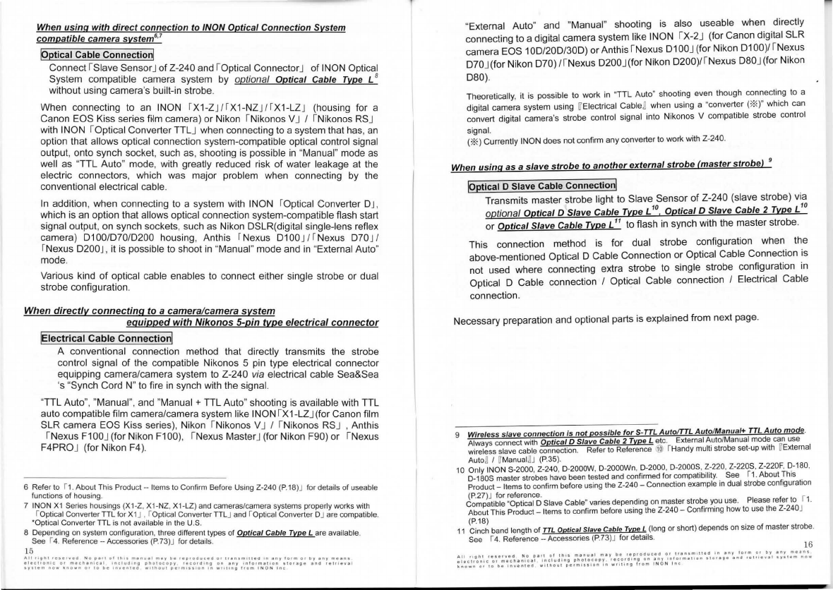
When
using
with
direct
connection to /NON Optical Conne
cti
on System
compatible camera
system
6•7
IQptical Cable Connection!
Connect rs 1ave SensorJofZ-240 and roptical ConnectorJ of INON Optical
System compa
ti
ble camera system
by
optional Optical Cable Tvpe L8
without u
si
ng
camera's bui
lt
-
in
strobe.
When connecting to an
IN
ON
f
X1-ZJ/fX1-
NZ
JJrX
1-LZJ (housi
ng
for a
Canon E
OS
Kiss
se
rie
s f"m camera) or Nikon rNikonos
VJ
/ rNikonos
RS
J
with
IN
ON roptical Converter TTLJ when connect
in
g
to
a system that h
as
, an
option that a
ll
ows opti
ca
l connection system-compatible opti
ca
l control
sig
nal
output, onto synch socket, such
as
, shooting
is
possib
le in
"Manual" mode
as
we
ll
as ''TTL Auto" mode, with gr
ea
tly reduced
ri
sk of water leakage at
the
elec
tri
c co
nn
ectors,
wh
ich was major problem when connecting
by
th
e
conventional elect
ri
cal cab
le
.
In
addition, when connecting
to
a system with INON [Opti
ca
l Conve
rt
er DJ,
which is an option
th
at a
ll
ows opti
ca
l connection system-compatible
fla
sh start
signal output, on syn
ch
socket
s,
such
as
Nik
on
DSLR{dig
it
al singl
e-
lens re
fl
ex
camera)
0100/070
/0200 hou
si
ng,
An
this f Nexus D100
J/[
Nexus D70
J/
fNexus D200
J,
it
is
possible
to
shoot
in
"Manual" mode and
in
"External Auto"
mode.
Va
rious kind of op
ti
cal
ca
ble enables
to
connect either s
in
gle strobe or
du
al
strobe
co
nfiguration.
When
directly
connecting
to
a
camera
/c
amera
system
equipped
with
Nikonos
5-pin
type
elec
tr
ical
connector
lElectrical Cable
Connection
!
A conventional connection method
th
at directly transmits the strobe
control signal of the
co
mpatible Niko
no
s 5 pin type electrical co
nn
ector
eq
ui
pping came
ra
/camera system to Z-240 via elect
ri
ca
l cable Sea&Sea
's "Synch Cord N" to
fi
re in synch with
th
e signa
l.
"TTL Auto", "Manual", and "Manual + TTL Auto" shooting is available
wi
th
TTL
auto compatible film
ca
mera/camera syst
em
like INON
rx
1-LZJ{for Canon film
SLR
ca
mera EOS
Ki
ss
se
ries), Nikon rNikonos VJ I I
Ni
konos
RS
J ,
An
t
hi
s
rNexus
F1
OO
J (for
Ni
ko
n F10
0)
, rNexus MasterJ (for Nikon F90) or I Nexus
F4PROJ (for Nik
on
F4
).
6 Refer to r1.
About
This
Produ
cl -
Items
to
Confirm
Before
Using
Z-240 (P.18)J
for
details
of
useab1e
functions
of
hou
sing.
7 INON _
X1
Series
housings
(
X1
-Z, X1-NZ, X1-LZ)
and
cameras/camera
syste
ms
proper
ly
works
with
r
o~t
1
cal
Converter
TIL
for
X1
J , r
Optical
Converter
TILJ
and
ropticalConverter DJ
are
co
mp
atible.
*Optical Converter
TIL
is
no
t
available
in
th
e U.S.
8
Depending
on
sys
t
em
configura
t
ion
.
three
different
types
of
Optical Cable Type L are
available
.
See r4. Refer
ence
-Accesso
ries
(
P.73
)J
for
de
tail
s.
15
"Exte
rn
al Auto" and "Manual" shooting
is
also useable when directly
co
nn
ecting to a digital camera system
li
ke INON
rx
-2
J (for Canon digital SLR
ca
mera EOS 1
OD
/
200
/
300)
or Anthisr N
ex
us 01
OO
J(for Nikon 0100
)1
rNexus
D7
0J(for Nikon
07
0) 1rNexus D200J(for Nikon 0200
)/r
Nexus D80J(for Nikon
080).
Th
eoretically, it is possible
to
work
in
"TTL Auto" shooting even though connecti
ng
to
a
digital
ca
mera system us
ing
~
El
ec
tri
ca
l
CableD wh
en
using a "conve
rt
er(
*)"
which
ca
n
convert digital camera
's
strobe control
sig
nal into Niko
nos
V
co
mpa
tib
le strobe co
nt
ro
l
signal.
(*)Cu
rrently lNON does not confi
rm
any
co
nverter
to
wo
rk
w
it
h Z-240.
When
using
as a slave
strobe
to
another
external
strobe
!master
strobe) 9
IQptical D Slave Cable Connection!
Transmits master strobe
li
ght to Slave Sensor of Z-240 (slave strobe) via
optio
nal
Optical D Slave Cable Type L' 0 Optical D Slave Cable 2 Tvpe L'0
or Optical Slave Cable Tvpe L
11
to
fl
ash
in
synch with
th
e master strobe.
Th
is
connection method is for
du
al strobe
co
nfiguration when
th
e
above-mentioned Optical D Cable Connection or Optical Cable Connection is
not used where connecting
ex
t
ra
strobe
to
si
ngle strobe configura
ti
on in
Opti
ca
l D Cable
co
nnection I Optical Cable co
nn
ection I
El
ectrical Cable
co
nn
ection.
Necessary preparation and optional parts is expl
ai
ned from next page.
Wireless slave connection is not possible for S-TTL Auto/TTL Auto/Manua
l+
TTL Auto mode.
Always
conn
ect
w
ith
Optical D Slave Cable 2 Type L
etc
.
External
A_
uto
/
Manua
l
mod~
can
use
wi
reless sl
ave
cable
co
nnection.
Refer
to
Re
f
erence
.@
fH
andy
mu
lt
i s
tr
obe
set-up
with
rr
E
xterna1
Auto
~
I
~
M
anu
al
!J
(P
.
35)
.
10 Only
IN
ONS-2000, Z-240, D-2000W, D-2000Wn, D-2000. D-200
05
. Z-220, Z-220$, Z-220F, D-180,
0-1
BOS
master
strobes
have
been
tested
and
confirmed
f
or
compatibi
l
ity.
See r1.
About
This
Product-
It
ems
to
confirm
before
using
the
Z-240-
Connection
example in
dual
strobe
con
figurati
on
(P
.27)
J
fo
r reference.
Compatible
"
Optical
O
Slave
Cab
le
~
var
i
es
depen
d
ing
on
master
strobe
you
use.
Please
refer
to
r1.
Abou
t
Thi
s P
rod
u
ct-
It
ems
to
confi
rm
befo
re
using
the
Z-240 -
Confirming
how
to
use
the Z-240J
(P.18)
11
Cinch
band
l
ength
of
TTL
Optical Slave Cable Tvpe L
(long
or
short)
depends
on
size
of
master
strobe
.
See r4. Reference -Accessories
(P
.73)J
for
details
. 16
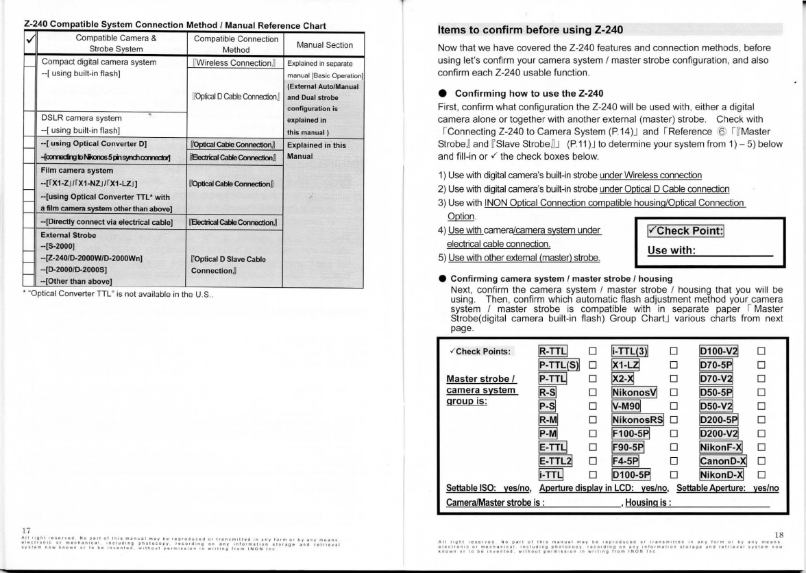
Z-
24
0 Compatible System Connection Method I Manual Reference Chart
1v-
Compatible
Camera
&
Compatible
Connection
Manual Section
Strobe
Sys
t
em
Method
H
Compact
digital
camera
system
IT
W
ir
eless
Connection
~
Explained in sepa
ra
te
--
[
using
built-in
flash)
manual [Basic Operation)
(External Auto/Manual
IT
Optical
DCatie
Connedion
~
and
D
ual
strobe
configuration
is
D
SLR
camera
sys
tem
. explained
in
--[using
built
-
in
flash)
this
manual )
f-
-[using
Optical C
onve
rt
er DJ
[f0ptica
1
Cable
eonnection
n Explained in
this
~bM<a-.ls
5
""1syiidloomocbj
ffEledrical
CableConnedionJJ
Manual
Film camera system
f-
-[fX1·ZJ/f
X1-NZ
J/f
X1
-L.Z
J] WO
plical
Cable
Con
nection
n
t---
-[usi
ng Optical
Converter
TI
L•
wit
h
afilm camera
~tam
other than above]
-[Directly connect via electrical cable]
ffEledricalCable~
External S
trobe
H
-[
S-2000
]
H -
[Z
-24
0/D
-2
000W
I
D-
2
000
Wn] W
Optica
l D
Slave
cable
H
-[
D-
2000
/D-2
000S
J
Co
n
nection
~
··[
Ot
her
than
ab
ove]
•
Opt
i
cal
Converter
TIL
"
1s
not
avai
labl
e
1n
the
U.S
..
17
Items
to
conf
irm
before
using
Z-240
Now
that we have covered the Z-240 features and connection methods, before
using let's confirm
your
camera system I
ma
ster
strobe configuration, and also
confirm
eac
h Z-240 usable function.
e
Confirm
i
ng
how
to
u
se
th
e Z-240
First, confirm
what
configuration the Z-240 wi
ll
be used with, either a digital
camera alone
or
together
with
another
external (master) strobe. Check with
fConnecting Z-240 to Camera System (P.14)J and fReference @
f ~
Master
StrobeBand
~
Slave
StrobeBJ (P.
11
)J
to determine your system from 1)-5) below
and fill-in
or
./
the check boxes below.
1)
Use
wi
th digital camera's built-
in
strobe under Wireless connection
2) Use with digital camera's built-in strobe under Optical D Cable connection
3)
Use with INON Optical Connection compatible housing/Optical Connection
Option.
4) Use with camera/camera system under
electrical cable connection.
5)
Use with other external (master) strobe.
l"'
Check
Point
:I
Use
with
:
e Confirming camera system I m
aster
st
rob
e I housing
Next, confirm the camera system I
master
strobe I housing that you will be
using. Then, confirm which automatic flash adjustment method your
came
ra
system I master strobe is compatible with
in
separate paper rMaster
Strobe(digital camera built-in flash)
Group
ChartJ various charts from next
page.
.f
Ch
ec
k
Po
ints: I
R-TT
Q D
li
-TTL(3l
l D 1
0100-v
® D
IP-
TTL(Sl
l D
~
D 1
010-sP
I D
Mas
ter
st
r
obe
I IP-TTQ D
~
D 1
010-v
® D
ca
mera
system
~
D
IN
ikono
s~
D l
oso-s
PI
D
gr
o
up
is
:
~
D
~
D
l
oso-v
~
D
~
D
I
N
ik
onosR
~
D 10200-s
PI
D
~
D IF100-5
PI
D 1
0200
-v ® D
IE-TTQ D IF90-5
PI
D
I
N
i
konF-
~
D
IE-TT
L21
D IF4-5
PI
D
l
canonO
-~
D
li
-TT
Q D 10 1
00
-s
PI
D
I
N
i
konO-
~
D
Settable
ISO
:
yes
/no,
A11
ertu
re
d
is
11
la
~
in
LCD
: yes/no,
Se
tta
ble
A11
erture:
~
es/
no
Camer
a/
Master strobe
is
: ,Housing is :
18
A
11
!lg
II 1 r
•••
r
v•d
N o
P•tl
ot
t
hh
m•nu•I
''"r
b•
••P•<>duc•d
01
lr•n•m•
1!
ao
'"
•nv
1orm
o•
1>y
•nr
me•n•
•l•clfon1c
or
macnanical
onclua1ng
pho1ocopy
1eco101ng
011
•nr
1n!orm•toon
slor•g•
•no
••lfl•v•I
•Y•1ern
now
~nown
or
to
b•
rnven1e0
w
rlhou1
perm11•1on
rn
wro11ng
!<om
! N O N
1nc

0_£!ical
Connection
~stem
Com_E_atible
Camera
~tern
Grol!E_Chart
Flash
A<justment
Settable Aperture Settable
./
Mfr. Housing/Camera Model displayed
Twe
I
SO
in
monitor Aperture
1--1
IN
ON
XHZ
. X1-NZ, X1-Z rn:m:J 0 0 0
Optical Converter
TT
L + compatible camera system 0 0 0
!---'
Optical Converter D + Nexus
0100
[EID
0 0 0
f-
Optical Converter D + Nexus
070/D70s
rn:ID 0 0 0
f-
Optical Converter D + Nexus
0200
0 0 0
Electrical
Connection
S stem Com atible Camera S stem Grou Chart
Flash
Se
ttable Aperture Settable
./
Mfr. Housing/Camera Model -I
SO
displayed pertur
c in monitor
INON
XHZ
.
X1-
NZ (with
Foc
us LighV Electrical
Connector)
I
X1
-LZ I 0 0 0
X-1Z (with
Focus
UghV
Electrical
Connector)
X-2
for
E
OS10D
(with Electrical
Connector
)
X-2 f
or
EOS20D(with
Elect
rical
Connector)
I
X2
-X I 0 0 0
X-2
for
E
OS30D(with
Electrical
Connecto
r)
X-2
for
E
OSS00/400
wi
th
Electrical Connect
or
Nikon
Nikonos
V [r
MOO
J/otrerlllanrBJmode] 0 0 0
(rM90J/rBJ
model
0 0 0
Ni
konos
RS
0 0 0
Anthis
Nexus
F100
[Camsa
Comector:
NCC-TMN3]
0 0 0
Nexus
Mast
er
{CamsaComector:
NCC-TMN3]
0 0 0
N
exus
F4
P
RO
• {CamsaComector:
NCC-TMN3]
0 0 0
Nexus 0100 {CamsaComector:
NCC-TMN3
] 0 0 0
[Camsa
Comector:
NCC-\/2
] 0 0 0
Nexus 070/0?0s {CamsaComector:
NCC-TMN3
] 0 0 0
{CamsaComector:
NCC-\/2
] 0 0 0
N
exus
{CamsaComector:
NCC-1MV3]
0 0 0
0200/080
11
{CamsaComector:
NCC-\/2
]
D200-V2
0 0 0
(continued
to
next
pag
e)
12
Complete
functionali
ty
is
not
guaranteed
with
all
pos
s
ibl
e camera/
housing
c
ombinations.
INON ch
ec
k product compatibility using available equipments and test conditions below.
(came
ra co
nn
ector NCC-TM)
· Connects single Z-240 to main synch connector via Synch Cord N.
(camera connector N
CC-V2)
· Connects single Z-240 to either of right or left synch connector via Synch Cord N.
(camera connector NCC-V3]
· Connects single Z-240 to main synch connector via Synch Cord N with 5 wires are connected inside
of the camera connector .
The output signal from the synch connector must be completely Nikonos V compatible (e.
g.
, when
used with a housing for multiple strobes, there must be no voltage reduction nor signal waveform
change from using synch connect
or
and signal from synch connector must be completely compatible
wi
th
Ni
konos V etc.) When using other than above configuration (especially in case below) some
function (
li
ke
TTL
Auto mode
or
mode
sel
ec
t
fu
nction)
of
Z-240 does not work properly dependi
ng
on
camera model, battery type/charge status, housing wiring/circuitry, configured equipment since output
signal from s
yn
ch connector
may
be not
comp
letely compatible with Nikonos V though theoretically
it
should work.
· Connects two or more Z-240 to multiple synch connectors via multiple Synch Cord N.
· Connects two or more Z-240 via
IT
Dual Synch
Co
rd
N
~
!NON can not guarantee complete functionality and you have to check its compatibility
wi
th your
camera system by yourself before using.
Please ref
er
to user manual for deta
il
of housing/camera or contact respective manufactur
er.
19
.-.11
right
rese•vea
N o
p•rl
ot
tni•
m•nu•I
m•v
be
r
eproauceo
or
t<•n•rnlt1ea
1n
•n
y
lotm
or
Dy
any
me>•n•
•I•
ctr
on,
c
o'
rne
ell
ii
n
le•
I
In
cl
~d
Ing
pl!
ot
o
copy
'
"co
rd
Ing
on
"n
y i n l o • m
~Ii
on
1 I
crag
e • n a t I !
roev
1 1
1y11em
now
;.
nown
"'
10
oe
onvenieo
w11t.ou1
o
"rn''''""
1n
w"
ion9
rrom
!NON
Inc
Flash
Settable Aperture
~ttabte
./
Mfr. Housing/Camera Model
~
disp
l
ayed
I
SO
in
monitor perture
Housing/Camera system which is;
Other 1) compatible wi
1h
Canon EOS500 EOS400
EOS300 E
OS
20
0 EOS 100
2) equipped with
Ni
konos v compatible
~1
3
0 0
synch co
nn
ector
3) connects with a camera via two
wi
r
es
,
GroundfTrigger[X], without using electronic
!---'
device
Housing/Camera system whi
ch
is:
1) compati
bl
e with
Ni
kon
F1
00 F90 F4
2) e
quip
ped with Nikonos v compatible
synch connect
or
~
13
0 0
3) co
nn
ects with a camera via two wires,
Ground I Trigger [
X),
or three wires,
Gro
und I Trigger (X] I Ready
Li
ght, without
f-
us
i.Q.9_
electronic
dev
ice
Housing/Came
ra
system which i
s;
1I
a:nµilE
v.i!i
Nl<rn
0
100
03'.Xl
D20l
0100
ooo
00'.l
O
'ICY70s.
DOO
2)
equippe
d with Nikonos v compatible
synch connector L!!I o!!Q:K_ " 0 0
3)
connects with a
ca
mera via
two
wi
res,
Grou
nd
I Trigger [
X],
or three wires, Ground I
Trigger
[X]
I Ready Light, without us
in
g
electro
ni
c device
13
IN
ON does not guarantee
comp
atibility with camera in specific housing. Please ask housing
manufacturer for their compatibility with Z-24
0.
0
0
0
20
A
ll
roghl
re•erveo
N o P "
't
ol
1h1s
manual
may
l>e
reproduced
Of
t<an•m•lled
1n
an
y f
orm
or
by
any
means
electron
oc
or
m
ecnan1c
3 1 I
nc
lu
d i
ng
pn
o
1ocopy
tecor
<t
1
ng
on
any
1n
!orm
a 1
1on
s 1
01age
ana
re
l
toeval
sy11em
now
l.no
wn
or
t o
1>e
1nv
en1
e d
wllhout
pe•rn
l••lon
on
wr
iting
rtorn
I N O N
Inc

Master
Strobe_JExternal
s
t
rob~
Gro':!.E_
Chart
Master Strobe
Flash~
S
~
Apertur
~
./
Mfr. ettable displayed Settable
Model
T)lle
ISO in monitor Aperture
I-
INON14
S-2000
/
[<jfnu~
.
(Depending on the
0-
2000/
LE-TTUE-
~
.
I P-
TTUS
/M I Camera System or
D-
2000S/
~
-TT
Ui-
TT
illj
Master
Strobe
you
are
Z-240
/
c!!.9_ita
lcamera] using.)
1--
1--
0-200
0W
/
[~
D-2000Wn
I
R-TT
US/M I
I-
. digital camera]
I-
[~
o]
o]
IP-
TTL(S
H x
I-
<!!g_ita
l
camera]
[-t{P-
nu
~
.
D·
180
/D·
180S
lE
-
TTUE
-
~
,
I P-S/M I (Depending on the
i
-TT
U
i-
TT
illj
Camera
System
or
<!!9._ita
lcamera] Master Strobe you are
1--
[~
"
using
.)
I R-S/M I
s
I-
dJg_ita
lcamera}
[
'f:__
nus.t.1.
~
-
220Z220SIZ-220F
I
E-
TTUE
-Taj
, I P-M I
I
i-
TT
L/~
TTL
IJi
1--
dJ.9..ita
lcamera]
[~
lillilii IR·
TTUM
I
I-
c!!g_ita
l
ca
mera}
1--
[+ F
oc
us
'=!.9_ht
Contro
ll
er
[in
a
ll
othe
r
cases
]
1--
Z-22
Nikon15
SB-104
,
SB-105
Sea
&
YS-25DX
,
YS-30
,
YS-60
.
YS-90
,
I-
Sea15
YS-900X
,
YS-120
.
YS-300
,
YS-350
YS
-25A
UT
O,
YS-90DX
_Ier:e-flash
cancel
OFF]
j
P-Sj_
1--
YS-25AUTO
.
YS-90DX
~e-flash
cancel
O
N]
1R-
S}
14
When configuring multiple strobe systems wilh external strobes other than the Z-240, because the
other strobe's flash control system is
di
fferent, there
may
be imbalance between each strobe's output.
Complete functionality for all available operational modes including auto flash mode. is not
guaranteed for non-recommended conn
ec
tion method. Please refer to r1. About this
product-
Items to confirm before using Z-240 -- Connection example in dual strobe configurationJ
(
P.
27)
for
details
.
15 Configuration compatibility has not been tested by INON. There
may
be imbalance strobe outputs
and INON can not guarantee all functionality.
21
All
"lln\
•••••
..
e<I
No
o•t1
of
tnh
m•nu•I
m•y
be
••proouc•O
or
t•lntm•
n
•o
1n
•ny
lo•m
or
by
1ny
me•ns
•lect<on1c
O•
mecn•nlt•I
1nc1ua1ng
onotocopy
••co•O•ng
on
any
1nlorma11on
11orag•
anO
•el11e
..
a1
1yst•m
now
~nown
or
10
1>1
onventeo
'""1no111
perm.111on
1n
wr1t•n11
ltom
INON
Inc
econfirming
useable
functions
H
ere
,
co
nfirm the Z-240
fu
nctions possible with your
camera
syst
em
I
master
strobe
co
nfiguration. F
or
de
tailed explanation
of
eac
h function,
see
"Z-240 Main
F
unc
tions (P.5)".For c
amera
sys
tems
not listed in this
cha
rt, try shooting so
me
t
est
image
s to
co
n
fi
rm functionalit
y.
Useable
functions
when
connecting
to
digital
camera
's
built-in
strobe
Aperture
:fable
Flash Function'611
F0shT)1:e
~~ble
d=
n1~=u'9
0,
A
~
-'[;'
~to~L°"E-~~~-~~_,,
al
crM-a-n-ua-I
f---
l9lQ
1--
1--
f---
~
1--
f---
0
0
0
x
0
0
0
0
0
0
0
0
0
x
0
0
x
x
0
0
0
0
0
0
0
0
x
x
0 0 0 0
x 0 0 0
x 0
O"
0
x 0 0 20 0
x 0
621
6.21
0 x22 O O
0 0 0 0
0 0 0 0
0 0 0 0
0 x 0 0
0 x 0 0
x x 0 0
x x
0
1
~
o
x x 0
18
0
Advanced
Cancel Circuit
0 "
0 "
Not Necessa
r/
1
0
0 "
0 "
Nol
Necessary
Not Necessary
Not Necessary
Not Necessary
Not Necessary
Clear
Photo
System
Com
__E".tibte
"
0
0
0
0
0
x"
x"
x"
x"
0
0
0
0
0
Focus
Light
Function
0
0
0
0
0
0
0
0
0
0 ; U
seab
le,
to.
; Pa
rtiall
y U
seab
le, x ;
Not
U
seable
16
When
configuring multiple strobe systems with external strobes other than the Z-240, because the
other s
tr
obe's flash system is different, there
may
be imbalance between each strobe's output.
Complete functionality for all available operational modes including auto modes is not guaranteed for
non-recommended connection
met
hod. Please refer to r1. About this product -Items to confirm
before using Z-240 -- Connection exam
pl
e in dual strobe configuration (P.27.)J
fo
r details.
17
Check sepa
ra
te paper rMaster Strobe (digital camera built-in flash) Group ChartJ for detail
of
points
to consider for each came
ra
system
18 U
sa
bl
e
only
with
optional
r
optical
0
Gable/Gap
SetType
L
with
Clear
Photo
System
Film
J
under
r
optical
0
Cable ConnectionJ . Not usable for [iWireless Connectionn . Refer to r2.Preparat
ion
-Camera System
P
reparation
(
P.4
6)
J
for
delail.
19 "Advanced Cancel Circuir automatically turns
rr
oF
Fnin
~
$-
TT
L
Auto
" mode regardless
of
Advanced
Cancel Circuit Switch setting
20 For cameras that do not show Aperture value
in
monitor, or cannot set ISO sensitivity, refer to your
camera manual and check "effective aperture range" and "ISO possible range" specifications. Then.
predict what settin
gs
the camera
wi
ll
automatically choose and set Z-240 accordingly. For details
see r2.Preparation -Camera System Preparation
(P.46)
J .
21 Set the Advanced cancel Circuit to
rr
oFF
n when using External Auto!Manual mode since the time-lag
between rpre-flashJ and rmain flashJ is approx.0.25 seconds which is out of range.
In
this case,
-1
.0
EV.
........,
-5.5EV. is usable but FULL
.......,
-0.S
EV. is not usable. Please refer to r2. Preparation -Strobe
Preparation -Setting the Advanced Cancel Circuit (
P.
52)J for detail. S-
TIL
mode does not have any
limitation with this master strobe group.
22 Not compatible since "S-TTL
Auto
" could get less accurate.
23 Only INON IX-2J under
rr
optica
l D Cable Connectionn is compatible. Contact your housing
man
uf
acturer for detail of compatibility with Clear Photo System or connection accessory ava
il
ability.
24 F
ocus
Light
may be r
ecor
ded in t
he
imag
e
dep
ending on housing/camera system setting or
shooting cond
it
ion. Refer to user manual
of
housing/camera system and 13. Using the Z-240 -
Focus Light Switch use (P.59)J for detail. 22
All
t19
n1
•
••••v•cl
No
P•ll
01 1n
11
manual
may
P•
••produced
or
lr•r>tm11ted
In
•n,
lo•m
or
or
•ny
m•en1
•l•clronoc
or
m
ec
nt
noc
a l
1ncluO•ng
pno1ocopy
recor<11ng
on
any
1nfotma11on
110••11•
an
O
r•l11•v•I
system
now
~
nown
or
to
~e
1nventeo
witnout
pe1m111lon
1n
w11t1ng
lrom
INON
Inc

Useable functions when using Optical Connection System compatible housings
,/
Settable Apertu"'
Settat<o
Flash Function
1:1
Advanced Clear Photo Focus
Fl3s'1T)!l0
ISO
~·
Aperture
ITL
External Manual Cancel
C1rcu1t
System light
Auto Compatible Functi
on
25
jR-TTJl..
_Q _Q
0 0
x"
0
Not
Ne
cess
;;:;
Not Necess-;y
_t:;.
"
lll}l] 0 0 0 x 0 0
Not
Necessary Not Necessary
6"
JP-'! 0 0 0 x 0 0 0 Not Necessary 0
0 =U
seable
,
t;
=Pa
rt
ia
ll
y
Useab
le, x =
Not
U
seable
Useable
functions
when
usin·g
with
electrical connection compatible
housing
,/
Settable Aperture Flash Function Advanced
F~~~~ti~
i~
t
I
SO
displayed
TTL
External Manual Manual+ Cancel Circuit
inmonitOI'"
Auto Auto
TILAuto
0 0 0 x 0 0 N
otNecessa
) 6
0 0 x 0 0 x
(Not
Necessaiy)
6"
0 0 0 x 0 0 (Not Necessaiy) 6 "
0 0 x x 0 x
(Not
Necessaiy)
6''
0 0 0 x 0 0 (N
otNeressaiy)
6"
0 0 0 x 0 0
(Not
Necessaiy)
6"
0 0 O" x 0 O"
(Not
Necessaiy)
6"
0 0 0 x 0 0 (Not Necessaiy)
6"
0 0
x"
0 0
x"
(Not
Necessaiy)
6"
0 0
x"
0 0
x"
(Not
Necessaiy)
6"
0 0
x"
0 0
x"
(Not
Necessaiy) 6 ''
0 0
x"
0 0
x"
(
Not
Necessaiy) 6 "
0 0
x"
0 0
x"
(
Not
Necessaiy)
6"
0 0
x"
0 0
x"
(Not
Necessaiy)
6'
'
0 0
x"
0 0 x" (Not Necessaiy)
6"
0 0 x x 0 x (
Not
Necessaiy)
6"
0 0
x"
0 0
x'
(Not Necessaiy)
6"
0 =U
sea
bl
e,
t;
=Pa
rti
ally
U
seab
le, x =N
ot
U
seable
25 Not controllable by a focus light switch
of
an optical connection compatible housing nor activated by
camera, camera system
or
master strobe's focus light operation.
26 Though Z-240 has rExternal AutoJ mode for a (r
TTLAut
oJ-compatible) film camera system, it is not
re
co
mmended for the reasons described below:
1)
Fine
ad
justment of the flash output requir
ed
for rExternal AutoJ is difficult
as
it
is
not possible
to
check the image immediately after shooting.
2)
r
nL
AutoJ
an
d rManual +TLLAutoJ mode offers auto light adjustment more easily.
27
mLAuto
JI and !'Manua
l+
TTL
Auto
/ mode are NOTava
ilabl
e because the camera
do
es
not
support (real t
im&TIL
Auto mode.
28 Exposure model.§.j{shutter prior
it
y auto).
rAl
(aperture priority aut
o)
o
r[M]
(manual) is recommended
to
user
TIL
AutoJorrM
an
ual +
TIL
Au
toJ
1e]
{program a
ut
o) does not a
ll
ow to use these flash modes.
23
Useable
functions
when
using
another
external
strobe
~-:r=1Setta~
Flash Function1
11
Advanced Cancel
F
0
uc~~i~$
~
,/
Fl3s'1
T
)!l0
Circuit
ISO
mon~or
jlll:
ITL
S-TTL
External Manual
Auto i'\uto
20
H Depending on camera x x 0 0 0 0
system
E:II!l
x O" 0 0 0 0
E:!I!JIDJ
x o"
6" 6"
(Not Necessary)
21
0
~
x x 0 0 (Nol Necessary)
6'
'
l!Ernl o" x 0 0 (Not Necessary)
6'
'
0 =U
seable
,
t;
= P
artia
l
ly
U
seab
le, x = N
ot
U
sea
bl
e
•Confirming
Connection Method
Next, be
ca
use camera/hous
in
g to strobe
co
nnections, and strobe
to
strobe
co
nnections differ for each
co
nfiguration type,
co
nfirm w
hi
ch optional parts a
re
necessary. For details on optional connection parts see 14. Referen
ce
--
Accessories
(P
.73)J or user manual of each product
".
Optical D Cable Connection I Optional Parts
Optional strobe a
rm
fo
r your camera system and optional "Optical D Cable"
parts (
Optical
D Cable · Cap
Set
Type L or
Optical
D Cable SS -Cap
Set
Type L
etc
.)
for
th
e strobe arm and option
al
parts to attach the "Optical D Cable"
pa
rt
s
is necessary.
Check separate
[B
asic Operatio
n]
11. Preparing To Take
Im
ages - Parts
necessary
For
connec
ti
on
/a
ttachment
(P
.17) J for detail of strobe a
rm
compatibility with each camera system. Also refer to separate paper I Optical
D Ca
bl
e Connection CompatibilityJ f
or
detail of "Optical D Cable" parts
(+optional parts to connect "Optical D Cable" parts.
Wireless Connection I Optional Parts
Optional "Wireless Connecti
on
Kit" (uni
ve
rsal accessory for
wi
reless
connection compatible camera system) and optional "wireless
co
nnec
ti
on
compatible
ba
se" set (Shoe Base Set or Grip Base D4 Set)
fo
r your
ca
mera
system is necessary.
Refer to separate paper ! Wireless Connec
ti
on CompatibilityJ for detail of
"wireless connection compatible base" compatibility
wi
th
each camera system.
29
For
dual
strobe
config
ur
ation
of
Z-240
with
S-2000/Z-240/
D-
2000W/D-2000Wn/D-2000/D
-
2000S/
D-180/D-180S,
~
Optical
D Cable
Co
nn
ectionDor
~
Op
t
ical
Cable Connectionn
is
recommended to
directly
con
ne
ct both strobes rather than using
~
Optica
l
0 Slave Cable
Co
nn
ectionn except using
~
Electrical
Cable
con
nectionn to co
nn
ect master strobe. Refer to r1.About T
his
Product -Items
to confirm before using the Z-240 -
Con
nection
exa
mple
in
dual strobe configuration (P.27)J for
details. 24
>,11
1111h! ,
.,
•
.,
,.
.,.;
N o
pan
of
t
i"•
m
•nu•I
m • y
O•
••pro
d
uc•d
Of
lranom11t
• d
In
•nv
!o•m
01
Oy
•nv
m11n1
el•cUon1c
or
m•C
ha
noc
a l
1nc
h 1d
1ng
ono
1
ocopy
••cor
d
ing
on
any
1n
!
orm3
11
0"
otO••g•
a
nd
••t•l•Y•I
1y1um
now
~
nown
01
10
b•
1nYe11
1e
d
w1
1
nou
1
p•rm1•11011
l11
w
•itlng
trom
IN
O N I
nc
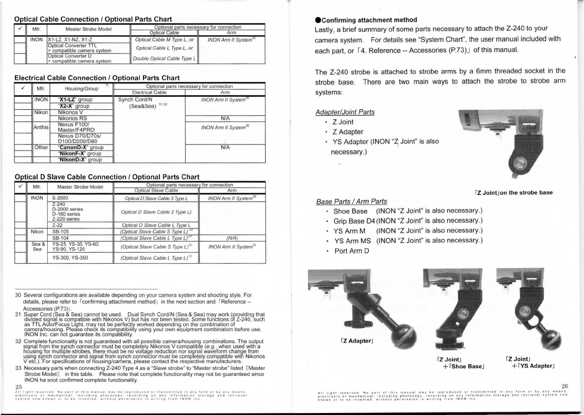
Op
tic
al Cable
Connection
I
Opt
ional Parts Ch
art
./
Mfr
.
Master
Strobe Model Qilliona[fillrts
necess
~
or
connection
QQ!ical
Cable
Arm
r---1
INON X1-LZ, X1-NZ, X1-Z Optical Cable M Type L. or /NON Arm II
SystemJO
Optical Converter
TTL
+
co~tible
camera
~tern
Optical Cable L Type L.
or
r---1
Optical Converter D
+
co
~Lible
camera
~tern
Double Optical Cable Type L
El
ect
rical Cable Conn
ect
ion
I Optional Pa
rt
s Chart
./
Mfr. Housing/Group
Qe!!ona~rts
necessa..!:Y_for
connec
ti
on
Eleclrical
Cab
le
Arm
1----1
INON "
X1
·LZ'...9_rol!E_
Synch
Co
rdlN
/NON
Arm
II
System
JIJ
"
X2-X
~oup
(Sea&Sea)
31
32
t--
Nikon Nik
onos
V
Nikonos RS N
IA
Anthis Nexus F100/ /NON
Arm
II System30
Mas
ter
lF4PRO
t---
Nexus D701D70sl
D100/D2001D80
t---
Other "
Canon
D-X
'...filoQE:
NIA
"N
ikonF-
X'
']ro!JQ:
"
N
i
ko
nD
·X
'...9_ro~
Opt
ical D Sl
av
e Cable Connect
ion
I Opt
ion
al Parts Chart
./
Mfr
. Master Strobe Model
Q.Q!ionaLfil!_rts
necessa for connection
~
cal
Stave Cable
Arm
f--
INON
S-2000
Optical D
Slave
Cable
3
7i
pe L /NON Arm fl System30
Z-240
0-2000 series Optical D Slave Cable 2 Type L)
0-160 series
r--
Z-220 series
Z-22
QpJ_ical
D Slave Cable L
~
L
r--
N
ikon
SB
-
105
_JQJ!J_;
cal Slave Cable S
~
Id_
"
SB
-
104
~
ical
Slave Cable L
'!re!!~
"]ti
!
~
Sea & YS-25. YS-30. YS-60, (Optical Slave Cable S Type L
)3l
/NON
Ami
II System
30
Sea YS-90,
YS-120
f--
(Opti
ca
l Slave Cable L Type L) n
YS-300, YS-350
30
Several
con
fi
gurations are available depending
on
your camera system
and
shooting style. F
or
details, please refer
to
fconfirming attachment methodJ
in
the
next section
and
fReference -
Accessories (P.73)
J.
31
~~~~cf~~dn~Tf;
c~~~~?i~n~~~
b~i~~~g5
v?~~:
~~~~~fg;~
'
~t~;re~~s~~l
fu~~tio
0
~~
Ufr~-v~~~
.
gs~ci~
~~~~1fi~~~no~u~l~~gs~
·
c~;6knifi
~~~~~T~i'lry~~i~~dy~~r~~d~~gq~~~:n~°c~~g~n
1
~~~~fbefore
use
.
INON
In
c.
can
not guarantee
its
compatibilit
y.
32
~~:;1fi~~b~~g~t~oy~~~Yc~n~~~cira~unif~
~~~~feY:~?~~~srnsr;~~
0
~i
tiiti?e
(~~~
.
in;~i~~~s~~e~~~pau
t
~~~~nsgy~~~
~~~~!~,~~~~~
5
Sihh;;fr;g~s~~~c~
0
c~~
1
~~~~o~e~~~\
1
b~
~6~~~~1~\;~;,t~~Wb~
h!?1~
e
Jf~~
os
Vele
.
).
For specifications of
hou
sing/camera, plea
se
contact the respective manufacturer
s.
33
Necessa
ry
parts wh
en
connecting Z-240 Type 4
as
a "Slave strobe" to "Master strobe" listed
rr
Ma
ster
Strobe
Mod
e
l
~
in
this
tabl
e.
Pl
ease note that complete functionality may not be guaranteed since
INON
ha
snot confi
rmed
complete functionality.
25
All
"tnr
•e•erved
No
o•n
of
tllo•
m•nuel
m•y
be
reproauc;ed
or
1<ansm111ea
'"
•ny
form
O•
by
any
mean•
elec;1<on1c
o•
meell•n•c•I
1nc1ua1ng
photocopy
•eco•alng
on
•ny
1ntorm•11on
sto••ll•
•na
ret11eva1
1y11em
no-..
lo.
no•n
Of
10
be
1nven1eo
w111\ou1
1>e•m,.s1on
1n
"'"ring
1rom
I N
ON
lne
econ
firming attach
me
nt
method
Lastly, a brief summary
of
some parts necessary
to
attach the Z-240
to
your
camera system. For deta
il
s see "System Chart
",
the user
ma
nual included with
each pa
rt
, or I4. Reference -- Accessories (P.73)J of
th
is manual.
The Z-240 strobe
is
attached to strobe arms by a 6mm threaded socket
in
the
strobe base. T
he
re are two main ways
to
attach the strobe to strobe arm
systems:
Adapter
/Joint Parts
ZJoint
ZAdapter
YS Adapter (!NON "Z Joint" is also
ne
cessa
ry
.)
rz
Joint
Jon
the
s
trob
e b
ase
Base Parts I
Arm
Parts
Shoe Base (INON "Z Joint"
is
also
ne
cessary.)
Grip Base
D4
(1NON "Z Joint"
is
also
ne
cessary.)
YS
Arm M (INON "Z Joint"
is
also necessary.)
YS
Arm
MS
(INON "Z Joint"
is
al
so
necessa
ry
.)
Port Arm D
rz
Jo
intJ
+r
sho
e B
ase
J fZ J
oint
J
+r
vs
Ad
ap
ter
J
26

27
econnection
example in dual strobe configuration
Basically same strobe model (Z-240) is recommended as an additional strobe.
In
dual strobe configuration
of
Z-240 with other strobes, the strobe output
balance may be different from your intention [e.g
.,
Though you inte
nd
to make
"flat" lighting with the same strobe output from both sides, the left and right
outputs would be imbalance].
This is proper operation caused by differences between Z-240 and other
strobes
in
specifications [Guide number at full flash/flash duration/flash
intensity per unit time].
To adjust flash output balance, it may be necessary to
IT
make flash
compensation on each strobeB ,
IT
attach a "diffuser"B , or
IT
change the
connection method from
!Optica
l D Slave Cable Connec
ti
onJ
=i
!Optical D
Cable ConnectionJ I !Wireless ConnectionJ I I Optical Cable Connec
ti
onJ B.
Refer to following as our test results for Z-240 with our strobe to understand
each strobe's characteristics, and as the recommended configurations.
Connection
method
There are two methods to connect two strobes. One is to connect each
strobe directly to a camera system ( IOptical DCable Connection I IWireless
Connection I IOptical Cable ConnectionJ or !Electrical Cable Connection I )
a
nd
another is to co
nn
ect one strobe
(-maste
r strobe) to a
ca
mera system
a
nd
connect the other strobe
(~slave
strobe) to the master strobe( IOptical D
Slave Cable ConnectionJ )
[Optical
D Cable
connection]
Each strobe is direc
tl
y connected to the
housing
(
Th
e
image
sh
ows
an
example
of a
compact
digital
camera
using
f
Optical
D
Cab
le
Cap
Set
T
ype
LJ a
nd
f
Optical
D
Cab
le
Type
LJ.
!D
oub
le
Optica
l
Cable
Type
LJ
is
u
sed
for
Optical
Cable c
onnection
.
[Optical DSlave Cable Connection]
Slave
strobe
is
connecte
d
to th
e
housing
via master strobe (The image shows an
example
of
a compact digital came
ra
, using
f
Optical
D
Cab
le
Cap
Set
Type
LJ
and
f
Optical
D
Slave
Cab
le2
Type
LJ.
Characteristic
of
each
connection
Optical D Cable Connection/Wireless Connection/Optical Cable Connection:
Each strobe is connected directly to the camera system and operates
independently. You can turn
OFF
one strobe or operates different flash
modes among dual strobe.
However each strobe is required to be compatible with light adjustment
system or preflash type
of
the came
ra
system.
Optical D Slave Cable Connection:
The input signal of
th
e slave strobe is the flash light
of
the master strobe,
thus the light adjustment system
of
the slave strobe depends
on
th
e light
adjustment system
of
the master strobe.
The slave strobe will not work
if
the master strobe is turned OFF. Also the
slave strobe can work
in
S-TTL only when the master strobe prope
rl
y works
in
S-TTL Auto mode. If the master strobe is compatible with the preflash
type camera system, the slave strobe does not necessarily have to be
compatible.
Electrical cable connection:
Theoretically each strobe should work independently as same as Optical D
Cable Connection/Wireless Connection/Optical Cable Connection.
"H
oweve
r
there
may
be
vo
lt
age
reduction
/
waveform
cha
ng
e
ca
u
sed
by
electrically
divergence.
INON
can
not
guarantee
complete
functionality
wit
h
all
possible
combination of camera/camera system. It is recommended to connect extra strobe to
a
master
strobe
(connected
to
a
camera
system
via
electrical
cab
l
e)
using
Optical
D
Slave Cable Connection. In case to co
nn
ect both strobes
to
a camera system directly
via electrical
cab
les, you have to check its compatibility and functionality
by
yourse
lf
.
Otherrequirements
to
be
co
nsidered
1) There are no limitations
in
connection methods when
Ising
qi
strobes
in
IT
ManualB mode. However, if the camera system is P-TT ,
~
.
~
IE-TIU
.I
E-TTL21.1
i-TTLJ.I
i-TTL(3\I, (a camera system with pre
fl
ash), the
strobe connected directly to the camera system must be one
of
the
following: [S-2000/Z-240/D-2000 series strobe] that allows "S-TTL Auto"
mode, [D-180 series strobe] that has "Advanced cancel circuit
,"
or [Z-220
series strobe or Z-22 with 'Focus
Li
ght Controller'] that has "Pr
ef
lash
Cancel Function."
2) For multiple strobe configuration, only S-2000, Z-240, D-2000 series
strobe, D-180 series strobe can work
in
auto light adjustment mode
in
combination with Z-240.
3) INON INC. confirms proper operation
of
IT
S-TTL AutoB mode for every
strobes
in
multiple strobes configuration up to 3rd slave strobe for
S-2000/Z-240
[Type
4]
/D-2000
[Type
4]
or 2nd slave strobe for Z-240
[Type
3/2/1] /D-2000
[Type
3/2/1 ] /D-2000S/D-2000W/D-2000Wn
when connecting strobes via "optical connection"(
IT
Optical D Cable
Co
nn
ectionB I
IT
Wireless ConnectionB I
IT
Optical D Slave Cable
ConnectionB
). [Following A) @Z-240 [Type
4)
is
4th slave strobe and
S-TTL functionality is not confirmed. ) 28
All
right
•e1etvea
N a
pan
al
11111
menull
mey
be
oeproauc:ed
01
11
1n1m1ttea
In
1ny
lo•m
01
by
any
mean•
elec11o
n ! c
or
meth1nlcel
.
including
photocopy
1eco1a1ng
an an
y
inlo•mallan
11orage
and
re111eve!
1y11em
now
~nawn
01
ID
be
lnvenled
wHhOu
t
pe1m1111on
1n
w111•ng
from
INON
Inc:
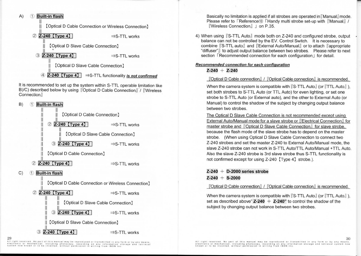
29
A)
CD
!Built-in flash!
II
II
[Optical D Cable Connection or Wireless Connection]
II
~ IZ-240
[Type
4]
I
=>
S-TTL works
II
II
[Optical D Slave Cable Connection]
II
•
@ IZ-240
[Type
4]
I
=>
S-TTL works
II
II
[Optical D Slave Cable Connection)
II
@ IZ-240
[Type
4]
I
=>
S-TTL functionality
is
not
confirmed
It
is
recommended
to
set up the system within S-TTL operable limitation like
B)/C) described below by using WOptical D Cable Connectionn·, WWireless
Connectionn
B)
CD
IBu'lt-in flash!
II
II
[Optical D Cable Connection)
II
~ IZ-240
[Type
4]
I
=>
S-TTL works
II
II
[Optical D Slave Cable Connection]
II
@ IZ-240
[Type
4]
I
=>
S-TTL works
I [Optical D Cable Connection)
II
~ IZ-240
[Type
4]
I
=>
S-TTL works
C)
CD
!Built-in flash!
II
II
[Optical D Cable Connection or Wireless Connection]
II
~ IZ-240
[Type
4]
I
=>
S-TTL works
II II
II II
[Optical D Slave Cable Connection)
II
l,'='I~~~~
II
@ IZ-240
[Type
4]
I
=>
S-TTL works
II
II
[Optical D Slave Cable Connection)
II
@ IZ-240
[Type
4]
I
=>
S-TTL works
Basically no limitation
is
applied if all strobes are operated
in
W
Manua1
nmode.
Please refer to !Reference@ ! Handy multi strobe set-up with WManuain I
WWireless Connectionn J
on
P.35.
4) When using WS-TTL Auton mode both on Z-240 and configured strobe, output
balance can not be controlled by the EV. Control Switch. It
is
necessary
to
combine WS-TTL auton and WExternal Auto/
Manua1
n
or
to attach Wappropriate
"diffuser"
nto adjust output balance between two strobes. Please refer
to
next
section !Recommended connection for each configurationJ for detail.
Recommended
connection
for
each
configuration
Z-240 + Z-240
[Optical D Cable connectionn I [Optical Cable
connection
~
is
recommended.
When the camera system
is
compatible with WS-TTL Auton (or
WT
TL Auton ),
set both strobes
to
S-TTL Auto (or TTL Auto) for even lighting,
or
set one
strobe
to
S-TTL Auto (or External auto), and the other
to
External Auto (or
Manual)
to
control the shadow
of
the subject by changing output balance
between two strobes.
The Optical D Slave Cable Connection
is
not recommended except using
External Auto/Manual mode for a slave strobe or [Electrical Connectionn for
master strobe and [Optical D Slave Cable
Connection
~
for slave strobe
because the flash mode
of
the slave strobe has
to
depend
on
the master
strobe. (When using Optical D Slave Cable Connection to connect two
Z-240 strobes and set the master Z-240
to
External Auto/Manual mode, the
slave Z-240 strobe can not work
in
S-TTL Auto/TTL Auto/
Manual+
TTL Auto.
Also the slave Z-240 strobe
is
3rd slave strobe thus S-TTL functionality
is
not confirmed except for using Z-240 [Type
4)
strobe.).
Z-240 + D-2000
series
strobe
Z-240 + S-2000
[Optical D Cable connectionn I [Optical Cable connectionn
is
recommended.
When the camera system
is
compatible with WS-TTL Auton (or
WT
TL Auton ),
set as described above" Z-240 + Z-240"
to
control the shadow of the
subject by changing output balance between two strobes.
30
A l l
11gn1
re
•e
rveo
N e
P•<l
of
1
n11
m1tnual
muy
o e
1eproauceo
er
11an
sm
,1
1
ea
1n
any
1erm
at
oy
any
me•n•
elec\fon•C
o•
m
•chan1cal
includ1n9
p h
c1oco
p y
fOCOf<l•nu
on
•ny
1nlorrnat•on
•lor•g•
ano
relr<
evul
•V•l•m
now
~nown
at
10
be
1nven1ed
wl1
tiou1
perrnhslon
'"
w1111ng
lrom
I N O N
Inc

Off
course full automatic
li
ghting
is
available
by
setting both
st
robes to S-
TIL
(or
TIL
auto). Since Z-240 flash system
is
different from D-2000 seri
es
strobe,
Z-240 fiashes much stronger
in
same fiash duration.
It
is
recommended
to
attach appropriate rDiffuserJ on the Z-240 to compensate imbalance of strobe
output.
· Action 1: Attach one
of
th
e following "Diffusers"
on
Z-240
to
slightly reduce the
amount of flash output.
•When using /iExternal Auto
)/
of
Z-240
..
1)
r- 0.5 White Diffuser 2 (External Auto)J
2)
r-
0.5 Blue Diffuser 2 (External Auto)J (sold separatelyl
(sold separatel
y]
•Wh
en /iExternal Auto
)/
of
Z-240 is NOT used
..
3)
r
--0
.5
White
Diffuser 2(TTUManual)J
4)r
-0
.5
Bl
ue
Diffuser 2 (TTUManual)J (sold separately]
· Action 2: Attach one of the following "Diffusers" on Z-240 to significantly reduce
the amount of flash output.
•Wh
en using /iExterna/ Auto
)/
of
Z-240
..
1) r- 1.5 White Diffuser 2 (External Auto)J (sold separatelyl
2)
r-1
.5 Blue Diffuser 2 (External Auto)J (sold separately]
•When [External Auto] of Z-240 is NOT used
..
3) r
-1
.5 White Diffuser 2 (TIL/Manual)J (sold separately]
4) r
-1
.5 Blue Diffuser 2
(TIUManual)
J (sold separately]
Choose the [color] of
th
e rDiffuser 2J according
to
your camera system,or
to
your
preference for the
co
lor tone.
In
general, good results can
be
obtained using
[blue] with Canon compact digital camera systems, and [ white] w
ith
o
th
er
camera systems.
The Optical D Slave Cable Connection
is
not recommended except using External
Auto/Manual mode
fo
r a slave strobe or [
El
ectrical ConnectionJ for master strobe
and [Optical D Slave Cable ConnectionJ for slave strobe, because the flash mode
of the slave strobe has to depend on the master strobe. {When using Optical D
Slave Cable Connection
to
connect two Z-240 strobes and set the master Z-240
to Manual mode, the slave Z-240 strobe can not work in
S-
TTL
Au
tofTTL
Auto/Manual +
TIL
Auto. Also the slave Z-240 strobe
is
3rd slave strobe thus
S-TIL
functionality
is
not confirmed except for using Z-240 (Type
4]
strobe.)
31
All
"llhl
•••••v.111
No
1"11
01
tl1+1
m•nu•I
nuy
be
r1p1oouc1a
O•
1ren1m11ua
'"
eny
!orm
01
by
eny
me•n•
etect•onlc
or
m1cn•n•c1I
onclu111ng
11no1ocopy
,.co•d•ng
on
any
1nlo•m•Hon
f1orege
end
r11111vat
1y11em
now
~no•n
01
10
be
onvented
w1thou1
ll"''"'••
lon
In
wrot
1ng
Ira"'
1NON
Inc
Z-240 + D-180 series
strobe
[Optical DCable connection] I [Optical Cable
co
nn
ection]
is
recommended.
As
the
flash
system
is
different,Z-240 emits stronger
in
the
same
flash
duration. Both
strobes will be same fiash duration
in
fo
ll
owing case.
. Case 1 When using Z-240
in
[
S-TIL
Auto] with
D-1
80 series strobe set to
[ External Auto] with camera's aperture
va
lue.
This tendency is more prominent when the fiash dura
ti
on
of
Z-240
is
short (when
flash output ofZ-240
is
relatively sma
ll
, such as macro imaging while the camera's
aperture
is
open
).
It is recommended to step down
0
~
2
stops (or more) on
D-1
80 I D-180S aperture
value comparing to camera's aperture setting
to
co
mpen
sa
te
the flash toward the
positive side.
The Optical D Slave Cable Connection
is
not recommended except using
[Electrical Connection] for Z-240 and [Optical D Slave Cable Connec
ti
on] for
D-180, because
th
e fiash mode of the slave strobe has
to
depend on the master
strobe.
Z-240 + Z-220 series
strobe
Recommended and possible connection methods differ depending
on
the camera
system.
(j)
When used with camera systems in
[P-TTQ,
~
.
~.
[E-TTQ
,
[E-TTL~
,[
i-TTQ.
[i-TTL(3~
group by "Optical Cable".
12'
When used with camera systems under conventional "electrical cable"
connection.
[Optical D Slave Cable connection
(s
lave strobe: Z-240 strobe l master strobe:
listed belowlJ
is
recommended.
Above case G) : Z-220 series
st
r
obe+
rFocus Light ControllerJ
Above case
(2J
:Z-220 series strobe
@ When used with camera systems in
[P-TTL{3~,
[R-TTQ,
i[§J
,
~group
by
"Optical Cable".
[Optical D Cable
co
nn
ec
ti
on
J I [Op
ti
cal Cable connectionJ is recommended.
32

Z-220 seri
es
strobe is not recommended
as
TTL slave strobe of Z-240 strobe
si
nce there
is
significant difference between
th
eir flash system.
Especially
in
case Z-240 flash amount
is
comparatively small, Z-220 strobe may
emit full amount
of
flash resu
lt
ing
of
TIL
error.
Since each strobe has different flash system, Z-240
wi
ll
flash much stronger
in
same flash duration
in
above (f)t
(J)
I@.
It
is
recommended to
a~ach
appropriate rdiffuser I
on
Z-240
to
compensate the
imbalance.
Optional rDiffuser 2(External Auto
)J
is
necessary when using rExternal AutoJ
mode w
hil
e suppliedr-o.5 White Diffuser 2 (TTUManual)J
is
for other modes.
· Action 1: A
tt
ach one of the
fo
ll
owing "Diffusers"
on
Z-240
to
slightly reduce the
amount
of
flash output.
•When
using
/!External
Auto
!/
of
Z-240..
1)
r-0
.5 White Diffuser 2 (External Auto)J [sold separately]
2)
r-
0.5 Blue Diffuser 2 (External Auto)J [sold separately]
•When /!External
Auto
!/
of
Z-240 is NOT used
..
3)
r--0
.5
Wh~e
Diffuser 2 (TTUManual}J
4)r- o.5 Blue Diffuser 2 (
TI
L/Manual)J [sold separately]
· Action 2: Attach one of the following "Diffusers" on Z-240
to
significantly reduce
the amount of flash output.
•When
using
/!External
Auto
!/
of
Z-240..
1) r
-1
.5 White Diffuser 2 (External Auto)J [sold separately]
2)
r-1
.5 Blue Diffuser 2 (External Auto)J [sold separately]
•When
IT
External Auto]
of
Z-240 is NOT used
..
3)
r
-1
.5 White Diffuser 2 (
TI
L/Manual)J [sold separately]
4) r
-1
.5 Blue Diffuser 2 (TIL/Manual)J [sold separately]
Choose the
IT
color] of the rDiffuser 2J according to your camera system,or
to
your
preference for the
co
lor tone.
In
general, good results can be obtained using
IT
blueJ with Canon compact dig
it
al camera systems, and
IT
whiteJ
wi
th
other
camera systems.
33
A.II
"ll"f
•••••ve<I
No
pen
ol
tn>•
manu•I
may
b"'
••1Pocluced
o•
t•an1m111e<1
+n
•ny
101m
or
Oy
eny
mean•
eleCl•Onoc
o•
m1c1>1n1c1I
oncluaong
onciro
co
oy
1ecor<11ng
on
any
ln
!
orm111on
•tO••ll•
and
•et,.eval
1y11em
now
~n
own
or
10
oe
1nven1ea
w<11>ou1
pe1m111•on
on
w1111ng
lrom
I N O N
In
c
Z-240 + Z-22
Recommended/available connection
is
differ depending on camera system
(j)
When
connecting
to IP-TIQ,
~
.
~.
le-nQ,
I
E-TIL~
,
li
-TI
Q,
li-
TIL(3) lgr
oup
camera system via
an
"Optical Cable":
~
When connecting to camera system via an "Electrical Cord":
[Optical D Slave Cable connection (slave strobe: Z-240 strobe master strobe:
listed belowln is recommended.
In
case of above (f) : Z-22+ rFocus Light ControllerJ
In
case
of
above
(1)
: Z-
22
IT
Optical D Slave Cable Connec
ti
onJ for above configura
ti
ons, uses r
nL
Optical
Slave Cable L Type LJ instead of
IT
Optical D Slave Cable 2 T
ype
U
@ When
connecting
to
IP-TIL(3M,
IR-TIQ,
I[§,~
group
camera system via
an "Optical Cable
":
[Optical DCable connectionn I [OpticalCable connection]
is
recommended.
r
nL
Sensor ZJ
is
necessary for
IT
Optical D cable connectionJ I
IT
Optical cable
connectionJ with Z-22.
IT
TIL
Auto strobe] Z-22 cannot
be
connected (as
TIL
slave strobe)
to
the master
strobe of Z-240, because the flash system of Z-240 and Z-22 are quite different.
When the flash output amount of Z-240
is
relatively small, there
is
a high
ri
sk of
TTL errors on Z-22, leading
to
make full flash.
As
me
ntioned above, Z-240 flashes much stronger
in
same flash duration
in
above
(f)
!
~
I
@
due to flash system difference.
It
is
recommended
to
attach appropriate "diffuser" on Z-240 to compensate
th
e
imbalance. Optional r Oiffuser 2 (External Auto) I
is
necessary when using
rExternal AutoJ mode while supplied r-0.5 White Diffuser 2 (TTL/Manual)J
is
for
other modes.
· Action 1: Attach one of the following rDiffusersJ on Z-240 to slightly reduce the
amount
of
flash output.
•When
using
/!External Auto
!/
of
Z-240...
1) 1
-0
.5 White Diffuser 2 (External Auto)J
2) r
-0
.5 Blue Diffuser 2 (External Auto)J [sold separately]
[sold separately]
•When /!External
Auto
!/
of
Z-240
is
NOT
used
..
3)
r
--0
.5
Whi
te Diffuser 2 (TIUManual}J
4)r
-o
.5 Blue Diffuser 2 (TTL/Man
ua
l)J [sold separately]
34
· Action 2: Attach one of the following "Diffusers" on Z-240
to
significantly redu
ce
the amount of flash output.
•Wh
en using
/!E
xternal Auto
//
of
Z-240..
1) I- 1.5 White Diffuser 2 (External Auto)J (sold separately)
2)
I
-1.
"5 Blue Diffuser 2 (External Auto)J (sold separately)
•When
VExternal Auto] of Z-240 is
NOT
used
..
3)
I-1.5 White Diffuser 2 (TTUManual)J (sold separately)
4) 1
-1
.5 Blue Diffuser 2 (TTUManual)J (sold separately)
Choose the VcolorB
of
the IDiffuser 2J according
to
your camera system, or
to
you
r
preference for the color tone.
In
general, good results can
be
obtained using
VblueB with Canon compact digital camera systems, and VwhiteB with other
camera systems.
35
Reference
@)
!Handymulti strobe set-up with
IT
External
Auto
~
I
IT
Ma
r;i
ual
~
and
lfWireless
Connection
~J
The External Auto mode calculating necessary amount
of
light when to
quench
by
strobe itself and the Manual mode emitting pre-selected fixed
flash amount,
is
triggered by built-in flash commencement only and basically
there
is
no
limitation
on
connection method
wi
thin physically possible
number of connected strobes.
It
is
possible to use the Z-240 equipped
wi
th
optional ! Mirror Unit (strobe)J
as a sub-strobe
to
eliminate shadow of a subject by connecting
to
a camera
system equipped with other external strobe.
To
work External Auto/Manual mode properly,
th
e Advanced Cancel Circuit
switch
is
properly selected depending on master strobe/camera system
group (master strobe flash system). Refer to 12. Preparation(External
Auto/Manual/TTLAuto) -Strobe preparation -- Setting the Advanced Cancel
Circuit
(P
.52)J and make sure
to
set the Advanced Cancel Circuit properly.
The !Mirror Unit (strobe)J has to be properly aim
to
the master strobe (The
"Camera Mirror"
is
not necessary
to
use External Auto/Manual mode).
Refer
to
"Wireless Connection Kit" user manual to adjust accordingly.
All
1111n1
•••••ved
No
oan
ot
11111
m•n11el
m a y
D•
r•prod
..
cea
or
1<an1m1t1e<1
rn
any
lorm
01
Oy
any
mean•
1lec1ron1c
or
macnan•c•I
1nclu<11ng
ono1ocoov
reco
..
11n9
on
any
1nlorma11on
1101•11•
ano
ralflaval
sysiem
no"'
kno
..
n
o•
to
D•
"'ven1eo
••1"0111
parm1e11on
'"
wtollng
l1om
INO
N
Inc
Description
of
Parts & Controls (seesepua1emanual[Basic0peration]foractua1inage,)
Operating Parts
1
:Flash Tubes
The flash tubes are arranged
in
a "T" configuration to provide a round 100
degree angle of illumination. Guide Number 24 (Air, I
SO
100 x m).
2:
Focus
Light
Aids manual and came
ra
's auto focus, and makes it easy to aim the strobe.
Activate Focus Light
by
pushing Focus Light switch.
The Focus Light uses Cree high-intensity power LED (XR-E series "
Q5
")
providing
1801m/20
° coverage and useable
as
independent diving light.
The Focus Light will turn
on
and then turn off automatica
ll
y as the internal
strobe fires; or, if shutter not released, after about 6 seconds. Or, by
pushing Focus Light switch continuously, or by turning
it
to
either right or left
"Lock" positions while pressing, the Focus Light will turn
on
and shine
continuously until the shutter
is
re
leased. Then, the Focus Light will turn
on
again automatically 0.5 seconds after the image
is
taken. For details see 13.
U
si
ng
the Z-240 -- Focus Light Switch use
(P
.59)J Refer
to
!
It
ems to
confirm before using Z-240
(P
.18)J for compatibility with different came
ra
system.
For
ultra
macro
shooting
in
"S
-
TTL"
Auto
mode
with
a close-up
lens
,
it
may
be
necessary
to
use
"
Red
Filter ·
LE
"
or
"Light Filter Sticker
(Red)"
for
accu
r
ate
exposure
con
trol
while
using
the
F
ocus
Light.
For
details, refer
to
this
section
's
r2o
.
Red
Filter ·
LE
/30
.
Light
Filter Sticker
(red)
(P.42)
J,
and
(Basic Operation] r2.
Quick
&
Easy
Auto
Imaging
(S-TTL}-Shooting
with
S-TTLAuto E
xposure
(P
.
27)
J.
The
Focus
Light color
tone
may
vary
(around
color temperature 6,
000K)
due
to
characteristic of
LED
where
you
may
notice difference
of
Focus
Light
color
tone
between
different
strobe
unit
when
you
use
multiple
strobe
configuration.
The
strobe
unit
is
equipped
with
built-in
vo
lt
age
stabilizer/power
saving
feature
which
intermittently
cha
r
ges
to
keep
the
unit fully
charged
.
The
Focus
Light
intensity
will
be
changed
simultaneously
with
this
charging
operation indicating
charging
status
of
the
unit
after
once
your
strobe
has
been
fully
charged
.
For
de
tail
,
please
refer
to
r1O:
Strobe
Ready
"
Red
Lamp
J
(P
.
39)
in
this
section
.
36
All
111n1
•••••v•d
N o
part
ol
11HI
manual
may
oa
1eproducaa
or
1ransm111ea
on
•ny
rorrn
or
1>1
•ny
me•n•
electronic
or
mecn
a
n1cal
1nclu<l1ng
p~o1ocopy
recording
on
•ny
1ntorrn•l•on
11on•11e
•n<I
re111eYal
•y•Um
now
~no
w
n
or
10
be
1nYen1eo
•1lnou1
P••m••••on
'"
w1111 n 9
lrorn
l
f<!
O
fol
Inc
Controls
37
4 : +1/4EV.
Compensation
Switch
In
External Auto mode, with
EV.
Control Switch set
to
match camera's
aperture value, using the
+1
/4EV. Compensation Switch will enable
+1
/4EV.
compensation. Placi
ng
the switch so
it
covers the Light Adjustment Sensor
sets
+1
/4EV.. to I
ON
J position. For detailed setting information, see 13.
Using the Z-240 -
EV.
Control Switch,
+1
/4
EV. Compensation Switch use
(P
.61)J
6 : Main
Mode
Switch
Set strobe power
to
ON/OFF Set flash mode, a
nd
in
Manual mode set
to
full output or incremental output settings. For details see 13. Using the
Z-240 -- Main Mode Switch Setting Method
(P
.57)J
7 :
EV.
Control
Switch
In
S-TTLAuto Mode, fine tune flash output.
In
External Auto mode set to
match camera/camera system aperture value.
In
Manual mode set flash
output and maximum flash output
in
Manual + TTL Auto mode. For details
see 13. U
si
ng
the Z-240 -- E
V.
Control Switch,
+1
/4E
V.
Compensation
Switch use
(P
.
61
)J
8: Focus
Light
Switch
Press this button
to
activate Focus Light. One push gives 6 seconds of
light before automatically turning off. Pushing
in
while rotating will set and
lock to continuous illumination mode. Focus Light Switch
is
also contro
ll
ed
by
Camera System without pressing the switch. For details see
13.
Using
the Z-240 -- Focus Light Switch use (P.59)J
9:
Advanced
Cancel
Circuit
Switch
In
External Auto or Manual modes under optical cab
le
co
nnection, turns
Advanced Cancel Circuit ON or OFF
by
this push switch. When using
IR-TTU.
~
.
l&MJ
and
I
P-TTL(S~
group cameras with built-in flash, or other
external strobes as the Master strobe,
it
is
ne
cessary
to
set the switch
to
WOFF
~
When connecting with electrical cable, set depending
on
your
camera/camera system and flash mode. For details see
12
. Preparation -
Strobe preparation
(P
.52)J
Alt
t1g1>1
••••r.•d
No
P••1
o!
11>,.
m•
nu•I
mar
be
reptooucea
cu
l••ntml!led
1n
•"Y
10!111
or
by
1ny
mean•
e1ec1!<1n1c
or
mecl>anlctl
1ncluo111g
pnatocGpy
recording
on
any
into•mt!lon
1 1
orage
and
tt
l
toaval
1r11em
now
~
nown
01
to
ba
1nv1n
1
ao
woinoul
pe1m••••on
'"
w111+ng
r1om
I N
ON
Inc
Connection
I
Sensors
3:
Light
Adjustment
Sensor
In
External Auto mode, this sensor measures light reflectivity
of
the subject.
For details on using External Auto see
lltems
to confirm before using Z-240
(P.18)J ,
12.
Preparation -When using with connecting to digital camera's
built-in strobe (P.46)J and 13. Using the
Z-240--
EV. Control Switch,
+1
/4EV.
Compensation Swit
ch
use (P.
61
)J
5: Slave
Sensor
The Sensor
to
attach a "fiber optics" for Optical D Cable connection/Optical
D Slave Cable connection or a "Mirror
Unit
(strobe)" (component parts of
optional
Wireless Connection
Kit
) for wireless connection (Receives light
from the master strobe). When connected
to
INON housing with
an
Optical
Cable, receives strobe's control signal.
17:
Synch
Connector
Electrical Connector compatible with Sea & Sea strobes (YS-30TTLDuo I
YS-90TTLDuo I YS-120TTLDuo etc
.).
Connectable
to
NIKONOS 5-pin-type electrical connector on the camera
system
via
Sea & Sea
Synch
Cord
I N. Ensure that the Synch Connector
Cap is fastened tightly when not using the Synchronized Connector.
22:
Sensor
Cap
The Sensor Cap must
be
put over the Slave Sensor when connecting
to
the
camera system using
an
electrical cable to prevent light coming
in
from
th
e
Slave Sensor. Refer
to
12.
Preparation -When using Electrical Connection
with a camera system (P.49)J
When connecting INON housing and Z-240 strobe with Wnon-wireless
type
~
old Optical D Cable/Optical Cable/Optical Slave Cable,
it
is
necessary
to
modify its Sensor Plug
(a
connector part to screw over strobe's slave
sensor)
wi
th
component part
of
this Sensor Cap. Refer to separate (Basic
Operation) 11. Preparing
To
Take Images -Attaching/connecting to camera
system (P.23)J for detail of
th
e modification.
18:
Synch
Connector
Cap
The Synch Connector Cap must be always put over the Synch Connector
except using
El
ectrical Cable Connection. Refer to separate manual (Basic
Operation) r1.Preparing
to
Take
Images-Attaching
I Connecting
to
Camera
System (P.23)J for details.
38
Alt
tl11n1
•e1e•v1d
N o
par
l o f
11111
m1nu1I
"''Y
D•
••orooucea
or
tr1n1m111eo
'"
any
!<11m
01
1>y
any
me1n1
elect1on1c
01
mecn1n1c
1 I
1nclud•ng
onotocooy
recora1ng
on
any
1nlo1m1t1on
110•
•
11•
and
••ll•t:Y•I
•J•
1
•"'
now
~nown
or
to
I>•
onYenteO
w
olhoul
P••m•••oon
1n
Wfl1'hll
trom
INON
Inc
Other manuals for Z-240
1
Other INON Camera Accessories manuals


