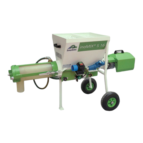
InoTec inoMIX S16 Installation instructions

EN
Read this entire original operating manual before starting work.
Original Operating Manual
inoMIX S16 continuous mixer

EN
Page 2 Page 3
Thank you for trusting INOTEC. By purchasing you have opted for a quality product.
If you have any suggestions or any issues, we would be delighted to hear your suggestions for improvement
and your feedback. Speak to the sales representative assigned to you or, in urgent cases, contact us directly.
We work constantly to further develop our products and reserve the right to make changes for technical reasons
relating to building legislation.
Yours faithfully
INOTEC GmbH
Legal notice
Address: INOTEC GmbH
Daimlerstraße 9-11
79761 Waldshut-Tiengen
Germany
Tel.: +49 (0)7741 6805 666
Fax: +49 (0)7741 6805 665
Web: www.inotec-gmbh.com
Last updated: August 2021
Document number: 10039462-OBA-EN
Contents
1 General information.................................................................................................................................. 5
1.1 Information about this manual ........................................................................................................................5
1.2 Symbol explanation ..........................................................................................................................................5
1.3 Information about this manual ........................................................................................................................5
1.3.1 Purpose of this operating manual...................................................................................................................................5
1.3.2 Disclaimer ......................................................................................................................................................................5
1.3.3 Warranty........................................................................................................................................................................5
1.3.3.1 Exercising claims .........................................................................................................................................................5
1.3.3.2 Warranty claims ..........................................................................................................................................................6
1.3.4 Carrying out repairs .......................................................................................................................................................6
2 Safety.......................................................................................................................................................... 6
2.1 Intended use ......................................................................................................................................................6
2.2 General risk sources...........................................................................................................................................6
2.2.1 Notices in the operating manual.....................................................................................................................................7
2.2.2 Performing checks before starting work .........................................................................................................................7
2.2.3 Conversions and changes...............................................................................................................................................7
2.2.4 Cleaning and maintaining the machine ..........................................................................................................................7
2.2.5 Changing the location of the machine ...........................................................................................................................7
2.3 Notices on the machine ....................................................................................................................................8
2.4 Personnel qualification......................................................................................................................................8
2.5 Responsibility of the operator..........................................................................................................................8
2.6 Personal protective equipment (PPE) ...............................................................................................................8
3 Technical data............................................................................................................................................. 9
3.1 Rating plate .......................................................................................................................................................9
3.2 Electrical control system, mixing rate, weight, dimensions ...........................................................................9
3.3 Water measuring system...................................................................................................................................9
3.4 Material hopper .................................................................................................................................................9
3.5 Motor..................................................................................................................................................................9
3.6 Metering shaft ...................................................................................................................................................9
3.7 Mixing shaft .......................................................................................................................................................9
3.8 Noise emissions..................................................................................................................................................9
3.9 Operating conditions.........................................................................................................................................9
4 Assembly and function ........................................................................................................................... 10
4.1 Scope of delivery of inoMIX S16 (item no. 10039462) ..................................................................................10
4.2 Functionality ....................................................................................................................................................10
4.3 Components .....................................................................................................................................................10
4.3.1 Description of the components ....................................................................................................................................10
4.3.1.1 Main frame with material hopper incl. metering shaft and wheels.............................................................................10
4.3.1.2 Control system..........................................................................................................................................................10
4.3.1.3 Water measuring system ...........................................................................................................................................11
4.3.1.4 Motor .......................................................................................................................................................................11
4.3.1.5 Mixing pipe and mixing shaft with mixing pipe cover ................................................................................................11
4.4 Displays and controls ......................................................................................................................................11
4.4.1 Water measuring system ..............................................................................................................................................11
4.4.2 Installing the water measuring system..........................................................................................................................11
4.4.3 Metering shaft ............................................................................................................................................................11
4.4.4 Mixing pipe and mixing shaft .......................................................................................................................................12
4.4.5 Motor ..........................................................................................................................................................................12
4.5 Connections......................................................................................................................................................12
4.5.1 Power connection (230 V) ...........................................................................................................................................12
4.5.2 Power connection of the motor....................................................................................................................................12
4.5.3 Water fitting connections.............................................................................................................................................12
4.6 Operating modes .............................................................................................................................................12
4.7 Accessories .......................................................................................................................................................13
4.8 Spare parts and diagrams ...............................................................................................................................14
4.8.1 Overview of inoMIX S16...............................................................................................................................................14
4.8.2 Water measuring system spare parts list .......................................................................................................................15
4.8.3 Metering shaft .............................................................................................................................................................16
4.8.4 Mixing pipe with mixing shaft and mixing pipe cover (item no. 10039949)...................................................................16

Page 5
EN
Chapter 1 General information
EN
Page 4
1 General information
1.1 Information about this manual
• This manual helps to ensure safe and efficient use of
the machine.
• Operating personnel must have carefully read through
and understood this manual before starting any work.
• Compliance with all the specified safety instructions is
a basic prerequisite for working safely.
• This manual is a component of the machine and must
be stored within direct proximity of the machine, acces-
sible to operating personnel at all times.
• In addition to the notices in these instructions, the local
accident prevention guidelines and national occupa-
tional health regulations also apply.
1.2 Symbol explanation
Hazard notices feature symbols to make them easier to
identify. These indicate the severity of the hazard.
• You must observe this information.
!
DANGER DANGER indicates an immediate hazard.
Death or serious injuries may result from non-compliance.
!
WARNING WARNING indicates a potentially dangerous
situation. Death or serious injuries may result from a failure
to avoid these situations.
!
CAUTION CAUTION indicates a potentially dangerous
situation. Minor or slight injuries may result from failure to
avoid these situations or damage to the machine or some-
thing in its vicinity.
NOTE
NOTICE draws your attention to useful tips for
effectively handling the machine.
1.3 Information about this manual
1.3.1 Purpose of this operating manual
The operating manual is used to provide information to the
operating manager, assembly fitters and machine operators
on the construction site. It contains important instructions
for safe use, optimum results and a long service life.
!
DANGER Risk of incorrect operation
Failure to observe the operating manual could put the
operator’s life and health at risk and damage the ma-
chine.
• Read this operating manual carefully before passing it
on to your assembly fitters or operators.
• Please ensure that assembly fitters and operators read
this operating manual carefully before they start install-
ing and commissioning the machine.
• Always keep the operating manual to hand and in a leg-
ible condition.
1.3.2 Disclaimer
All technical information, data and instructions for use con-
tained in this operating manual reflect the state of the art at
the time of printing and are based on our experience thus
far and the best of our knowledge.
The manufacturer cannot be held liable for any damages as
a result of:
• Failure to comply with this manual
• Improper use
• Assignment of non-trained personnel
• Unauthorised alterations
• Technical changes
• Use of non-approved spare parts
1.3.3 Warranty
Statutory warranty periods of 12 months from the date of
purchase/the date of invoice of the industrial end customer
apply to our machinery.
1.3.3.1 Exercising claims
In the event of a warranty claim, send the entire machine,
along with the invoice, to our headquarters in Wald-
shut-Tiengen.
Contact our free INOTEC service
hotline beforehand on +49 7741 6805 777.
4.8.5 Mixing pipe cover for mixing pipe (item no. 10039950)................................................................................................17
4.8.6 Mixing shaft for mixing pipe (item no. 10039948)........................................................................................................17
4.8.7 Drive unit (item no. 10039958) ....................................................................................................................................18
5 Transport and storage ............................................................................................................................. 19
5.1 Safety notices for transport............................................................................................................................19
5.2 Transport inspection........................................................................................................................................19
5.3 Damage report.................................................................................................................................................19
5.4 Complaints .......................................................................................................................................................19
5.5 Packaging .........................................................................................................................................................19
5.6 Transport of the used machine in vehicle......................................................................................................19
5.7 Storage .............................................................................................................................................................19
6 Installation ............................................................................................................................................... 20
6.1 Delivery condition of the machine .................................................................................................................20
6.2 Connecting the metering shaft and motor....................................................................................................20
6.3 Assembling the mixing pipe and mixing shaft..............................................................................................20
6.4 Connecting the electrical control system.......................................................................................................21
6.5 Installing the water measuring system..........................................................................................................21
7 Commissioning ....................................................................................................................................... 22
7.1 Adding material to the material hopper........................................................................................................22
7.2 Opening and emptying bags of material.......................................................................................................22
7.3 Commissioning inoMIX S16 ............................................................................................................................22
7.4 Function after commissioning ........................................................................................................................22
7.5 Changing material ...........................................................................................................................................22
7.6 Change of location on the construction site .................................................................................................22
8 Operation, use.......................................................................................................................................... 23
8.1 Checking operating performance...................................................................................................................23
8.2 Checking the consistency of the material......................................................................................................23
8.3 Correcting flow fluctuations...........................................................................................................................23
8.4 Work break.......................................................................................................................................................23
8.5 End of work......................................................................................................................................................24
8.5.1 Switching off the machine ...........................................................................................................................................24
8.5.2 Dismantling and cleaning the mixing pipe and mixing shaft..........................................................................................24
8.5.3 Dismantling the motor und metering shaft...................................................................................................................24
9 Cleaning and decommissioning ............................................................................................................. 24
9.1 Cleaning process ..............................................................................................................................................24
9.2 After cleaning ..................................................................................................................................................25
9.3 Decommissioning.............................................................................................................................................25
9.3.1 Running the machine until it is empty and switching it off............................................................................................25
9.3.2 Mixing pipe and mixing shaft with mixing pipe cover ...................................................................................................25
9.3.3 Water measuring system ..............................................................................................................................................25
9.3.4 Dismantling the motor and metering shaft...................................................................................................................25
10 Maintenance........................................................................................................................................... 26
10.1 Maintenance plan ..........................................................................................................................................26
10.2 Dirt trap sieve in the water inlet ..................................................................................................................26
10.3 Dirt trap sieve in the pressure reducing valve.............................................................................................26
10.4 Wear limit for metering shafts .....................................................................................................................27
10.5 Wear limit for mixing shafts .........................................................................................................................27
11 Faults, causes and solutions ................................................................................................................. 27
12 Dismantling and disposal ..................................................................................................................... 29
12.1 Safety..............................................................................................................................................................29
12.2 Dismantling ....................................................................................................................................................29
12.3 Disposal ..........................................................................................................................................................29
13 Systems................................................................................................................................................... 30
13.1 EC declaration of conformity ........................................................................................................................30
13.2 General Terms of Business of the company INOTEC GmbH........................................................................31
13.3 Circuit diagram for inoMIX S16 ...................................................................................................................32
14 Order form.............................................................................................................................................. 33
15 Index ....................................................................................................................................................... 34
16 Locations ................................................................................................................................................ 35

Page 6 Page 7
EN EN
Chapter 2 Safety Chapter 2 Safety
1.3.3.2 Warranty claims
Claims apply only where material or manufacturing faults
exist and where machinery has been used properly. Wear
parts are not covered by the warranty. All claims shall be-
come void if third-party parts are installed, where the ma-
chinery has been improperly used or stored and in the event
of obvious non-compliance with the operating manual. In
this connection, we refer you to our General Terms of Busi-
ness.
1.3.4 Carrying out repairs
Repairs may only be carried out by employees at our
INOTEC service centres.
2 Safety
2.1 Intended use
You may only operate this machine if the following
conditions are met:
• The inoMIX S16 is suitable for processing all factory
pre-mixed and machine-compatible dry mortars. Load
the continuous mixer only with dry goods (e.g. bagged
goods).
• Only use the machine within its limits of application
and according to the technical data.
• Pay particular attention to the safety and warning
notices outlined in this original operating manual.
!
DANGER Failure to use the inoMIX S16 properly
could put the user’s life and limb at risk and damage
the inoMIX S16 or other assets.
!
WARNING Danger due to misuse!
Improper use of the inoMIX S16 can lead to hazardous
situations.
• Never use the inoMIX S16 continuous mixer to create
other products, such as food.
• Never operate the inoMIX S16 continuous mixer us-
ing values out of the ranges specified in the “Technical
Data”.
2.2 General risk sources
!
DANGER Electrical voltage.
Danger of death due to electric shock.
• Work on the electronic control system may only be per-
formed by a qualified electrician.
• Switch off the machine and pull out the mains plug.
• Secure the machine against unexpectedly being switched
back on.
!
DANGER Rotating shaft.
Danger of death due to being pulled into the machine
and crushed.
When the motor is running, the metering shaft ro-
tates, even if the mixing pipe has been removed with
the mixing shaft!
• Do not reach into the rotating shaft.
• Do not place any objects into the rotating shaft.
1. Before working on the metering and mixing shaft, inter-
rupt the external power supply.
2. To do this, press the red pushbutton.
3. Pull out the mains plug.
4. Secure the machine against unexpectedly being switched
back on.
!
WARNING Water jet.
Risk of injury and risk of property damage due to es-
caping water.
1. Interrupt the external water supply by closing the water
valve.
2. In order to release the pressure (approx. 2 bar), open the
water drainage valve on the water measuring system.
3. Remove the hose from the external water supply.
4. Do not point the water jet at other people or yourself.
2.2.1 Notices in the operating manual
!
CAUTION Safety notices in the operating manual
alert the operating personnel to any immediate dan-
ger. Please observe all the technical and hazard notic-
es in this operating manual.
2.2.2 Performing checks before starting work
!
WARNING Defects or damage can put the safety of
operating personnel at risk and impair the functional-
ity of the machine.
• Before commencing work, check the machine for any
obvious external damage or defects.
• Do not commission the machine if you notice any dam-
age to or defects in the machine.
• Ensure that the damage and/or defects are rectified.
2.2.3 Conversions and changes
!
DANGER Conversions or changes can put the safe-
ty of operating staff at risk and impair the functional-
ity of the machine.
• Do not make any changes, additions or conversions to
the machine without first consulting Inotec GmbH and
obtaining its written approval. Otherwise, the operat-
ing license will become void.
2.2.4 Cleaning and maintaining the machine
!
WARNING Cleaning and maintenance work can put
the safety of operating staff at risk and impair the
functionality of the machine.
1. Switch off the machine and pull out the mains plug.
2. Secure the machine against unexpectedly being
switched back on.
3. Before cleaning with the water jet, cover all the open-
ings that water must not penetrate into for safety and
functional reasons.
4. After cleaning, remove all the covers which were at-
tached to protect against the water.
2.2.5 Changing the location of the machine
!
CAUTION Changing location can put the safety of
operating staff at risk and impair the functionality of
the machine.
1. Switch off the machine and pull out the mains plug.
2. Lift the machine up using the mixing pipe and place it
in a new location on the building site.
3. Always install the machine in such a way that it is level
and stable.
4. Secure the machine against undesirable movements.
5. Reconnect the machine to the external power supply
before restarting the machine.

Page 8 Page 9
EN EN
Chapter 2 Safety Chapter 3 Technical data
2.4 Personnel qualification
INOTEC offers training sessions on operating the inoMIX
S16. Use INOTEC service for the initial commissioning of
the machine; this also serves as an opportunity to provide
operators with training on how to operate the mixer.
!
DANGER If the inoMIX S16 is operated by unqual-
ified individuals, this could put the life and health of
the operating staff at risk and cause property damage
to the inoMIX S16 or other assets.
2.5 Responsibility of the operator
• Only task trained or instructed staff with operating the
inoMIX S16.
• Define employees’ responsibilities for operating, setting
up, maintaining and servicing the machine clearly.
• Only task untrained staff or individuals who have not re-
ceived any instruction with operating the machine when
there is a trained or instructed specialist available to su-
pervise them.
• Work on the electronic control system may only be per-
formed by a qualified electrician.
2.6 Personal protective equipment (PPE)
!
CAUTION PPE – particularly gloves, safety boots, a
safety helmet and safety goggles and respiratory pro-
tection – must be used.
2.3 Notices on the machine
!
DANGER Safety notices on the machine make oper-
ating staff aware of imminent danger.
The following warning notices are affixed to the inoMIX
S16:
• WARNING. Do not reach into the machine (1).
• If there is a risk of frost, drain the water (2).
• This QR code will take you to the original operating man-
ual of the mixer (3).
• The machine may only be operated via a connector pro-
tected with an RCD (FI) IΔn ≤ 30 mA (4).
• Observe all the safety and hazard notices that are at-
tached to the machine.
• Always keep the safety and hazard notices in a clearly
legible condition.
Safety notice to
the right of the
GEKA coupling
Safety notice
under the rating
plate
1
QR code
on the
motor side
3
Safety note on the
power input
2
4
3 Technical data
3.1 Rating plate
1
5
4
23
Item Component Value
1 Manufacturer, address and contact
details, CE marking
-
2 Name and type of machine -
3 Machine’s year of construction -
4 Machine number -
5Technical data
- Voltage
- Current
- Output
230 V
16 A
1.1 kW
You must always state the machine number if you would
like to order spare parts, have any queries or would like
to make a complaint. You will find this information on the
rating plate or on the delivery note.
3.2 Electric control system, pump output, particle size,
weight, dimensions
Mains voltage 230 V, 50 Hz
Mains supply line (CEE plug) 16 A (to be supplied by
customer)
Output 1.1 kW
Fuse min. 16 A
Mixing capacity max. 16 l/min.*
Weight approx. 58 kg
Dimensions:
Length without mixing pipe 1,030 mm
Length of mixing pipe 500 mm
Width 600 mm
Height 890 mm
* Material-dependent – observe the material manufacturer’s instructions.
3.3 Water measuring system
Pressure being too low From 2 to 6 bar
Pressure reducer
ex-works setting
2.5 bar
Solenoid valve 230 V, 50 Hz
Supply line ¾ inch water pipe
(to be supplied by
customer)
3.4 Material hopper
Fill quantity max. 45 l
3.5 Motor
Output/rotation speed 1.1 kW, 387 U/min-1
Installation position Motor horizontal
Electrical data f = 50 Hz , I = 7 A,
U = 230 V, IP 55
Insulation class F, ED = S1
Colour unvarnished
3.6 Metering shaft
Diameter 51 mm
Diameter
(wear limit)
45 mm
3.7 Mixing shaft
Maximum height of mixer
blades:
55 mm
Minimum height of mixer
blades
(wear limit)
50 mm
3.8 Noise emissions
Guaranteed sound power
level LWA
78 dB (A)
3.9 Operating conditions
Temperature range 2 - 45 °C
Relative humidity, maximum 80 %

Page 10 Page 11
EN EN
Chapter 4 Assembly and function Chapter 4 Assembly and function
4 Assembly and function
4.1 Scope of delivery of inoMIX S16 (item no. 10039462)
The scope of delivery is generated using the components
ordered and can be checked using the delivery note.
• Frame
• 2 running wheels
• Material hopper
• Gear motor
• PU mixing pipe
• Mixing shaft
• metering shaft
• Water fitting
• Operating manual
4.2 Functionality
The continuous mixer is filled with bagged goods as stan-
dard. The mixing and metering shafts are directly driven by
a gear motor. During operation, the dry material is con-
veyed from the material hopper into the mixing pipe via the
metering shaft. In the mixing pipe, the dry material − with
the addition of water − is mixed using the mixing shaft, to
form a homogeneous, paste-like product, and is conveyed
out of the mixing pipe.
NOTE
Note the optimum assembly sequence.
1. Push the metering shaft into the main frame.
2. Attach the motor to the material hopper by means of
the quick-release fastener, and ensure that the metering
shaft is connected to the motor via the motor bracket.
3. Insert the motor plug into the machine’s socket.
4. Assemble the mixing pipe by using both eccentric fas-
tenings on the main frame and push the mixing shaft
with the mixing pipe cover into the mixing pipe. En-
sure that the mixing shaft is connected to the metering
shaft.
5. To lock the mixing pipe cover, turn it clockwise so that
both ball heads lock in the recesses provided in the steel
frame.
6. Connect the main switch to the external power supply
(230 V / 16 Hz)
4.3 Components
1
2
3
4
5
4.3.1 Description of the components
Item Component
1 Main frame with material hopper
incl. metering shaft and wheels
2 Control system
3 Water measuring system
4 Motor with motor covering
5 Mixing pipe incl. mixing shaft
4.3.1.1 Main frame with material hopper incl. meter-
ing shaft and wheels
The socket for the motor, main switch and water measuring
system are attached to the main frame. Push the metering
shaft into the main frame. The motor is attached to the
main frame by the quick-release fastener and the mixing
pipe by two eccentric fastenings. Finally, push the mixing
shaft with the mixing pipe cover into the mixing pipe. To
lock the mixing pipe cover, turn it clockwise so that both
ball heads lock in the recesses provided in the steel frame.
Material hopper with hopper mesh, toothed rail and
metering shaft
4.3.1.2 Control system
Connect the main switch to the external power supply (230
V / 50 Hz). The cross-section of the supply cable must be
at least 2.5 mm2! The inoMIX S16 may only be run with an
approved FI circuit breaker (30 mA) (RCD).
4.3.1.3 Water measuring system
The water measuring system is attached to the main frame.
The optimum water quantity is set by opening and closing
the needle valve.
4.3.1.4 Motor
The motor is attached to the main frame together with the
motor cover by a quick-release fastener. The CEE plug of
the motor is plugged into the socket on the main frame.
The metering shaft previously pushed into the main frame
is connected to the motor bracket attached to the motor.
4.3.1.5 Mixing pipe and mixing shaft with mixing pipe
cover
Assemble the mixing pipe by using both eccentric fasten-
ings on the main frame and push the mixing shaft with
the mixing pipe cover into the mixing pipe. Ensure that the
mixing shaft is connected to the metering shaft. To lock the
mixing pipe cover, turn it clockwise so that both ball heads
lock in the recesses provided in the steel frame.
4.4 Displays and controls
1
2
Electronic fitting with green pushbutton (1) to switch on the
machine, and red pushbutton (2) to switch off the machine
4.4.1 Water measuring system
43
16
25
Description of the components in the diagram
Item Component
1 Water drainage valve
2 Needle valve
3 Pressure reducer
4 GEKA coupling with sieve insert
(external water connection)
5 Solenoid valve
6 Pressure gauge
WARNING Water jet.
Risk of injury and risk of property damage due to es-
caping water.
• Do not point the water jet at other people or yourself.
4.4.2 Installing the water measuring system
1. Connect the supply hose to the external water supply.
2. Open the water valve until a steady water jet comes out
of the hose in order to both clean the water hose of dirt
and ventilate it.
3. Then close the valve on the external water supply.
4. Connect the external water hose to the GEKA coupling
of the water fitting.
5. Connect the water drainage valve to the water fitting.
6. Connect the internal water hose to the mixing pipe.
4.4.3 Metering shaft
The metering shaft is connected to the motor via motor
bracket and rotates during operation in the main frame.
The mixing shaft is also connected to the metering shaft via
a plug-in connection. The metering shaft can be pulled out
for cleaning and maintenance work.
This image illustrates the connection from the motor
(right) to the metering shaft, and from the metering shaft
to the mixing shaft.

Page 12 Page 13
EN EN
Chapter 4 Assembly and function Chapter 4 Assembly and function
4.4.4 Mixing pipe and mixing shaft
The mixing shaft is firmly screwed to the mixing pipe cov-
er. The mixing shaft is connected to the metering shaft via
a plug-in connection. The mixing shaft in the mixing pipe
rotates during operation. It is protected from tampering
by the mixing pipe cover. The mixing shaft alongside the
mixing pipe cover can be pulled out of the mixing pipe for
cleaning and maintenance work.
!
DANGER Rotating shaft.
Danger of death due to being pulled into the ma-
chine and crushed.
When the motor is running, the metering shaft ro-
tates, even if the mixing pipe has been removed with
the mixing shaft!
• Do not reach into the rotating shaft.
• Do not place any objects into the rotating shaft.
1. Before working on the metering and mixing shaft, inter-
rupt the external power supply.
2. To do this, press the red pushbutton.
3. Pull out the mains plug.
4. Secure the machine against unexpectedly being switched
back on.
4.4.5 Motor
!
DANGER Electrical voltage
Danger of death due to electric shock.
1. Work on the electronic control system may only be per-
formed by a qualified electrician.
2. Switch the machine off. To do this, press the red push-
button.
3. Pull out the mains plug.
4. Secure the machine against unexpectedly being switched
back on.
4.5 Connections
4.5.1 Power connection (230 V)
AC (alternating current) connection (230 V).
4.5.2 Power connection of the motor
CEE plug of the motor in the socket
4.5.3 Water fitting connections
1
2
Connection of the external water supply (1), connection of
the mixing pipe to the water supply (2).
4.6 Operating modes
The ready-mixed material can be filled into any container
(bucket, wheelbarrow, etc.).
4.7 Accessories
The following accessories can be supplied for the inoMIX S16.
230 V extension cable, 3 x 2.5 mm², length 10 m,
16 A, Schuko plug and socket
Item no.
10015208
PU mixing pipe for inoMIX S16
Including mixing shaft, mixing pipe cover and holders
Mixing shaft
Complete metering shaft with two dowel pins (M8 x 50)
Item no.
10039949
10039948
10039947
Water metering pipe with holder for inoMIX S16
For visual control of the water quantity
Water quantity
litres per hour
100 - 1,000 l
Item no.
10040799

Page 14 Page 15
EN EN
Chapter 4 Assembly and function Chapter 4 Assembly and function
4.8 Spare parts and diagrams
The spare parts for the inoMIX S16 are designated with
numbers in the following images. The individual items are
described in the table under the respective diagrams.
Description of the table columns:
Item: Corresponds to the number in the drawing
designating a spare part.
Item no.: INOTEC item number.
Installation
quantity: number of parts of this item when installed
in the original inoMIX S16.
UQ: Unit of quantity of this item.
Name: Name of the spare part.
4.8.2 Water measuring system spare parts list
7
8
3
2
14
15
4
5
9
6
1
13
12 11
10
Item Item no. Installation
quantity
UQ Name
1 10006499 1 Units Needle valve, 1/2” connection
2 10036240 1 Units Pressure reducer D06F-1/2”, with transparent sieve cup
3 10017821 1 Units Pressure gauge 0 - 10 bar, 1/4” at back
4 10022373 1 Units GEKA coupling, 1/2”, ET
5 10006007 1 Units Brass sieve insert
6 10006470 2 Units Hose nozzle, 1/2” ET x 13 mm nozzle
7 10021968 1.0 Meter Black rubber water hose, 1/2” with yellow stripes
8 10006471 1 Units Angular, 1/2”, 90°, galvanised, IT
9 10022443 2 Units Hose clamp, 1-ear, 19.2 - 21.8, (1/2”)
10 10023112 1 Units Solenoid valve 1/2”, 230 V, type 6213A
11 10022156 1 Units Galvanised bend, DN 15, 1/2”, IT/ET
12 10006493 1 Units T-piece, 1/2” ET x 1/2” IT x 1/4” IT
13 10022166 1 Units Double nipple, 1/2“, galvanised
14 10017912 1 Units Mini ball valve, 1/4”, IT + ET
15 10022372 1 Units GEKA coupling, 1/2”, IT
NOTE
Use the order form at the end of this op-
erating manual to order spare parts.
4.8.1 Overview of inoMIX S16
65
1
3
2
7
4
Item Item no. Installation
quantity
UQ Name
10039462 1 Units inoMIX S16 continuous mixer for bagged goods,
1.1 kW 230V / 50Hz
1 10039946 1 Units Complete main switch for inoMIX S16
2 10011185 2 Units Wheel (puncture-free)
3 10006192 2 Units Starlock cap, d = 20 mm
4 10039962 1 Units CEE socket
5 10039958 1 Units Complete drive unit for inoMIX S16
6 10039949 1 Units Mixing pipe complete with GEKA coupling, mixing pipe cover and
mixing shaft
7 10039460 1 Units Water measuring system

Page 16 Page 17
EN EN
Chapter 4 Assembly and function Chapter 4 Assembly and function
4.8.3 Metering shaft
2
1
Metering shaft
Item Item no. Installation
quantity
UQ Name
1 10039947 1 Units Complete metering shaft
2 10004698 2 Units Dowel pins, M8 x 50
4.8.4 Mixing pipe with mixing shaft and mixing pipe cover (item no. 10039949)
4
2
5
6
3
1
7
Mixing pipe
Item Item no. Installation
quantity
UQ Name
1 10039134 1 Units Transparent mixing pipe insert
2 10039951 1 Units Mixing pipe frame/mixing pipe holder
3 10039948 1 Units Mixing shaft
4 10039950 1 Units Complete mixing pipe cover
5 10017068 2 Units Eccentric lock, size 0 with drawbar eye
6 10036239 1 Units Clamping plug G1/2 for plastic mixing pipe
7 10022373 1 Units GEKA coupling, 1/2”, ET
4.8.5 Mixing pipe cover for mixing pipe (item no. 10039950)
1
2
3
4
5
Mixing pipe cover
Item Item no. Installation
quantity
UQ Name
1 10039950 1 Units Complete cover for mixing pipe (incl. items 2 + 3)
2 10039952 2 Units Ball head for mixing pipe cover
3 10006175 1 Units Plastic transfer for the mixing shaft
4 10040694 1 Units Allen screw, M8 x 12, left-hand thread
5 10040419 1 Units Splash guard washer, 8.4 x 35 x 1.5
4.8.6 Mixing shaft for mixing pipe (item no. 10039948)
Mixing shaft
Item Item no. Installation
quantity
UQ Name
1 10039948 1 Units Mixing shaft

Page 18 Page 19
EN EN
Chapter 4 Assembly and function Chapter 5 Transport and storage
4.8.7 Drive unit (item no. 10039958)
2
3
1
4
5
8
7
6
9
Motor
Item Item no. Installation
quantity
UQ Name
1 10007515 1 Units Gear motor, 1.1 kW
2 10039953 1 Units Complete motor flange (incl. items 7, 8, 9 and 10)
- 10039955 1 Units Motor flange without attachments
3 10041323 1 Units CEE plug 3 x 16 A, IP 44
4 10039956 1 Units Tappet bracket with paddles
4.1 10039933 1 Units Radial shaft seal
5 10016644 1 Units Bow handle
6 10039944 2 Units Centring bolt
7 10039945 2 Units Eccentric bushes
8 10039954 1 Units Clamping lever for quick-release fastener
9 10041184 1 Units Motor flange seal
NOTE
Use the order form at the end of this operating manual to order spare parts.
5 Transport and storage
5.1 Safety notices for transport
!
DANGER Slipping machine
Danger of death for drivers and transport users.
• Ensure that the machine is in a secure position during
transport.
• Secure the machine against slipping.
!
WARNING Risk of injury posed by carrying or lifting
machine
• The machine weighs 58 kg. To prevent overloading and
damaging the spine, at least 2 people must lift or carry
the machine.
5.2 Transport inspection
NOTE
Check the machine to ensure that all
components are present and for transport damage
immediately upon receipt.
• Do not leave any parts in the packaging.
5.3 Damage report
Proceed as follows in the event of externally visible
transport damage:
1. Write a damage report with the following details:
- Your client address
- Name of the transport company and the driver
- Date and time of the delivery
- Order number and machine name
according to the delivery note
- Description of the damage
- Signature of the driver
- Signature of the recipient at the customer’s premises
2. Have the transport damage confirmed by means of the
driver’s signature.
3. Send one copy of the damage report to
the transport company and another to
Inotec GmbH.
4. And clarify the possible ways in which the damage
could be remedied with one of our service centres (see
second last page)
5.4 Complaints
Claims for compensation relating to transport damage can
only be made if the delivery company is informed of the
same without undue delay.
5.5 Packaging
The new machine will be shipped cellophane-wrapped on
a Euro pallet.
• Dispose of the packaging material as required by law.
5.6 Transport of the used machine in vehicle
!
DANGER Slipping machine.
Danger of death for drivers and transport users.
1. Ensure that the machine is stored securely during trans-
port.
2. Secure the machine against slipping.
NOTE
Leaking material residue
• Clean the machine before transport.
• Secure the machine in the vehicle using suitable fixing
materials.
5.7 Storage
If the machine is not likely to be used for an extended
period of time, thorough cleaning will be required.
Store the machine under the following environmental
conditions:
• Dry
• Frost-free
• Protected from dust
• Protected against corrosion (e.g. salt water)

Page 20 Page 21
EN EN
Chapter 6 Installation Chapter 7 Commissioning
6 Installation
Observe the following notices when assembling and posi-
tioning the machine:
Installation location requirements
• Ensure that there is enough space around the machine
to enable filling of the material hopper and machine op-
eration.
• Install the inoMIX S16 on an even and horizontal surface.
• Prevent the machine from sliding by locking the wheels.
The mixing pipe points downwards.
• Cover the floor underneath the machine with a plastic
sheet, if it is not on a firm, tarmacked surface.
• Keep the machine in a dry, protected area in wet weather.
• Prevent direct exposure to sunlight, especially while in
continuous operation, in order to prevent the motor
from overheating.
6.1 Delivery condition of the machine
The inoMIX S16 is shipped with the metering shaft inserted
and motor flanged on. The mixing pipe and mixing shaft
still have to be attached.
6.2 Connecting the metering shaft and motor
1. Push the metering shaft into the main frame.
2. Attach the motor to the (1) main frame by means of
the quick-release fastener, and ensure that the meter-
ing shaft is connected to the motor.
3. Insert the CEE plug of the motor into the socket on the
main frame.
1
6.3 Assembling the mixing pipe and mixing shaft
1. Assemble the mixing pipe by using both eccentric fas-
tenings on the main frame.
2. Push the mixing shaft with the mixing pipe cover into
the mixing pipe. Ensure that the mixing shaft is con-
nected to the metering shaft.
3. To lock the mixing pipe cover, turn it clockwise so that
both ball heads lock in the recesses provided in the steel
frame.
!
DANGER Rotating shaft.
Danger of death due to being pulled into the machine
and crushed.
When the motor is running, the metering shaft ro-
tates, even if the mixing pipe has been removed with
the mixing shaft!
• Do not reach into the rotating shaft.
• Do not place any objects into the rotating shaft.
1. Before working on the metering and mixing shaft, inter-
rupt the external power supply.
2. To do this, press the red pushbutton.
3. Pull out the mains plug.
4. Secure the machine against unexpectedly being switched
back on.
6.4 Connecting the electrical control system
1. Connect the inoMIX S16 only to regulation 230 V con-
struction site power distribution points with FI circuit
breakers (30 mA) (RCD).
2. Ensure that the connection is protected by a 16A fuse
and that the cross-section of the supply cable is at least
2.5 mm2.
3. Connect the supply cable to the connector plug on the
On/Off switch.
Connector plug on the On/Off switch
6.5 Installing the water measuring system
1. Connect the supply hose to the external water supply.
2. Open the water valve until a steady water jet comes out
of the hose in order to both clean the water hose of dirt
and ventilate it.
3. Then close the valve on the external water supply.
4. Connect the external water hose to the GEKA coupling
of the water fitting (1).
5. Connect the water drainage valve to the water fitting
(2).
6. Connect the internal water hose to the mixing pipe (3).
7. Open the valve on the external water supply.
1
32
!
WARNING Water jet.
Risk of injury and risk of property damage due to es-
caping water.
1. Interrupt the external water supply by closing the water
valve.
2. In order to release the pressure (approx. 2 bar), open
the water drainage valve on the water measuring sys-
tem.
3. Remove the hose from the external water supply.
4. Do not point the water jet at other people or yourself.

Page 22 Page 23
EN EN
Chapter 7 Commissioning Chapter 8 Operation, use
7 Commissioning
7.1 Adding material to the material hopper
Warning Risk to health due to dust.
When cleaning the machine, inhaled dust can cause
long-term lung damage or other adverse health ef-
fects.
• The machine operator or people working in the dust area
must each wear a dust mask when cleaning the machine.
• Find out about the technical rules for hazardous sub-
stances (TRGS 559) “Mineral dust” on the homepage of
the German Social Accident Insurance Institution (www.
bgbau.de).
Warning Risk of injury due to powdery material
When adding bagged goods to the material hopper,
swirling material may pose a risk of injury, especially in the
region of the eye and face.
• Always wear safety goggles.
7.2 Opening and emptying bags of material
Warning Observe the applicable occupational safety
regulations (e.g. respiratory protection)
To clean the bags of material, proceed as follows:
1. Place the bag of material on the hopper mesh with the
tooth rail.
2. Tear open the bag of material by using short forward and
backward movements.
3. Move the bag sideways and upwards and then empty
the contents into the material hopper.
4. Observe the applicable occupational safety regulations
(e.g. respiratory protection, etc.).
5. Dispose of the empty bags of material and other pack-
aging material in an environmentally friendly manner in
accordance with the instructions provided by the packag-
ing manufacturer.
7.3 Commissioning inoMIX S16
1. Connect the inoMIX S16 only to regulation 230 V con-
struction site power distribution points with FI circuit
breakers (30 mA) (RCD).
2. Ensure that the connection is protected by a 16A fuse
and that the cross-section of the supply cable is at least
2.5 mm2.
3. Connect the supply cable to the connector plug on the
On/Off switch.
4. Fill the material hopper with bagged goods.
5. Open the valve on the external water supply, and check
the water inlet pressure on the pressure gauge (2 bar).
6. Press the green pushbutton.
7. Turn the needle valve of the water fitting. This allows
you to change the flow volume of the water and thus
precisely determine the material consistency.
7.4 Function after commissioning
The motor starts up, the dry material from the material
hopper is transported into the mixing pipe via the meter-
ing shaft. At the same time, the solenoid valve opens and
allows the water to flow into the mixing pipe. The material
is moistened by the inflowing water and homogeneously
mixed by the mixing shaft, and conveyed to the downpipe
section of the mixing pipe.
7.5 Changing material
1. Run the inoMIX S16 until it is empty and dry.
2. Clean the material hopper, metering shaft, mixing pipe
and mixing shaft.
7.6 Change of location on the construction site
The inoMIX S16 is equipped with two wheels, and a han-
dle is attached to the hopper. The mixer can therefore be
moved on the construction site easily. Its mixing pipe can
also be used to lift and move the inoMIX S16 around. To
do this, disconnect the mixer from the electricity and water
supply.
NOTE
This QR code will take you to the original
operating manual of the mixer.
8 Operation, use
8.1 Checking operating performance
1. If you notice any deviations in the operating behaviour,
decommission the inoMIX S16 immediately.
2. Ensure that the damage and/or defects which led to the
deviating operating behaviour are rectified.
8.2 Checking the consistency of the material
Ensure an even, paste-like material consistency during
operation.
• The viscosity may change, especially in warm weather
conditions.
Material too rigid Increase the water supply
by re-adjusting it on the
needle valve of the water
fitting
Material too runny Reduce the water supply by
re-adjusting it on the nee-
dle valve of the water fitting
8.3 Correcting flow fluctuations
1. Check the water inlet screen and clean it if it is dirty.
2. Check the water pressure at the supply line and regulate
it accordingly, if necessary.
3. Check the pressure reducer and regulate it, if necessary.
8.4 Work break
If the duration of a work break exceeds the setting time of
the material to be processed, there is a risk of the material
setting during the break.
1. Stop the mixer by pressing the red pushbutton.
2. Pull out the mains plug.
3. Pull out the plug of the motor from the socket.
4. Use an external water hose for cleaning.
5. Remove the internal water hose that connects the mix-
ing pipe to the water valve.
6. Pull the mixing shaft (screwed to the mixing pipe cover)
out of the mixing pipe. To do this, turn the mixing pipe
cover anti-clockwise to the left.
7. Open both eccentric fastenings to separate the mixing
pipe from the main frame.
8. Clean the mixing shaft and mixing pipe with water over
a suitable drip tray or bucket.
NOTE
Carry out this cleaning process before any
longer breaks from work (> 0.5 hours). Do not operate
the mixing pipe forcibly from the outside (e.g. by hit-
ting it with a hammer).
!
DANGER Rotating shaft.
Danger of death due to being pulled into the machine
and crushed.
When the motor is running, the metering shaft ro-
tates, even if the mixing pipe has been removed with
the mixing shaft!
• Do not reach into the rotating shaft.
• Do not place any objects into the rotating shaft.
1. Before working on the metering and mixing shaft, inter-
rupt the external power supply.
2. To do this, press the red pushbutton.
3. Pull out the mains plug.
4. Secure the machine against unexpectedly being switched
back on.
!
WARNING Water jet.
Risk of injury and risk of property damage due to es-
caping water.
1. Interrupt the external water supply by closing the water
valve.
2. In order to release the pressure (approx. 2 bar), open
the water drainage valve on the water measuring sys-
tem.
3. Remove the hose from the external water supply.
4. Do not point the water jet at other people or yourself.

Page 24 Page 25
EN EN
Chapter 9 Cleaning & decommissioning Chapter 10 Maintenance
8.5 End of work
8.5.1 Switching off the machine
1. Stop filling with bagged goods in sufficient time.
2. Empty the material hopper of the main frame and the
mixing pipe.
3. Stop the mixer by pressing the red pushbutton.
4. Pull out the mains plug.
5. Pull out the plug of the motor from the socket.
8.5.2 Dismantling and cleaning the mixing pipe and
mixing shaft
1. For cleaning, connect a water hose to the GEKA cou-
pling (left) provided for this purpose on the water valve.
2. Remove the internal water hose that connects the mix-
ing pipe to the water valve.
3. Pull the mixing shaft (screwed to the mixing pipe cover)
out of the mixing pipe. To do this, turn the mixing pipe
cover anti-clockwise to the left.
4. Open both eccentric fastenings to separate the mixing
pipe from the main frame.
5. Clean the mixing shaft and mixing pipe with water over
a suitable drip tray or bucket.
6. Interrupt the external water supply by closing the water
valve.
7. In order to release the pressure (approx. 2 bar), open
the water drainage valve on the water measuring sys-
tem.
8. Remove the supply and cleaning hose from the water
valve.
8.5.3 Dismantling the motor and metering shaft
1. Remove the motor by opening the quick-release fasten-
er that connects the motor to the main frame.
2. Pull out the metering shaft from the main frame.
3. Remove dry residual material by using a suitable broom.
Use a suitable container to collect the residual material.
9 Cleaning & decommissioning
9.1 Cleaning process
1. Stop filling with bagged goods in sufficient time.
2. Empty the material hopper of the main frame and the
mixing pipe.
3. Stop the mixer by pressing the red pushbutton.
4. Pull out the mains plug.
5. Pull out the plug of the motor from the socket.
6. Remove the internal water hose that connects the mix-
ing pipe to the water valve.
7. Pull the mixing shaft (screwed to the mixing pipe cover)
out of the mixing pipe. To do this, turn the mixing pipe
cover anti-clockwise to the left.
8. Open both eccentric fastenings to separate the mixing
pipe from the main frame.
9. Clean the mixing shaft and mixing pipe with water over
a suitable drip tray or bucket.
10. Interrupt the external water supply by closing the water
valve.
11. In order to release the pressure (approx. 2 bar), open
the water drainage valve on the water measuring sys-
tem.
12. Remove the supply and cleaning hose from the water
valve.
13. Remove the motor by opening the quick-release fasten-
er that connects the motor to the main frame.
14. Pull out the metering shaft from the main frame.
15. Remove dry residual material by using a suitable broom.
Use a suitable container to collect the residual material.
!
DANGER Rotating shaft.
Danger of death due to being pulled into the ma-
chine and crushed.
When the motor is running, the metering shaft ro-
tates, even if the mixing pipe has been removed with
the mixing shaft!
• Do not reach into the rotating shaft.
• Do not place any objects into the rotating shaft.
1. Before working on the metering and mixing shaft, inter-
rupt the external power supply.
2. To do this, press the red pushbutton.
3. Pull out the mains plug.
4. Secure the machine against unexpectedly being switched
back on.
!
WARNING Water jet.
Risk of injury and risk of property damage due to es-
caping water.
1. Interrupt the external water supply by closing the water
valve.
2. In order to release the pressure (approx. 2 bar), open
the water drainage valve on the water measuring sys-
tem.
3. Remove the hose from the external water supply.
4. Do not point the water jet at other people or yourself.
9.2 After cleaning
Note the optimum assembly sequence:
1. Insert the metering shaft.
2. Attach the motor to the main frame by using the
quick-release coupling.
3. Mixing pipe and mixing shaft with mixing pipe cover.
4. Connect the water and electricity supply.
9.3 Decommissioning
9.3.1 Running the machine until it is empty and
switching it off
1. Stop filling with bagged goods in sufficient time.
2. Empty the material hopper of the main frame and the
mixing pipe.
3. Stop the mixer by pressing the red pushbutton.
4. Pull out the mains plug.
5. Pull out the plug of the motor from the socket.
9.3.2 Mixing pipe and mixing shaft with mixing pipe
cover
1. Remove the internal water hose that connects the mix-
ing pipe to the water valve.
2. Open both eccentric fastenings to separate the mixing
pipe from the main frame.
9.3.3 Water measuring system
1. Interrupt the external water supply by closing the water
valve.
2. In order to release the pressure (approx. 2 bar), open
the water drainage valve on the water measuring sys-
tem.
3. Remove the supply hose from the water valve.
9.3.4 Dismantling the motor and metering shaft
1. Remove the motor by opening the quick-release fasten-
er that connects the motor to the main frame.
2. Pull out the metering shaft from the main frame.
3. Remove dry residual material by using a suitable broom.
Use a suitable container to collect the residual material.

Page 26 Page 27
EN EN
Chapter 10 Maintenance Chapter 11 Faults, causes and solutions
10 Maintenance
Have the machine inspected once a year by a specialist
workshop. Replace parts which are subject to wear as soon
as the wear limits have been reached. Portable machines,
like the inoMIX S16, must be subject to an annual elec-
trical inspection according to the implementing regulation
for electrical plant and operating resources (DGUV V3). This
inspection may only be carried out by a qualified electrician
(e.g. electrical engineer, electrical technician, master electri-
cian, senior electrician, foreman electrician or assistant elec-
trician). Electrical specialists work at all INOTEC service cen-
tres, conducting electrical inspections in line with DGUV V3.
To arrange an inspection, call the INOTEC service hotline on
+49 7741 6805 777.
WARNING Cleaning and maintenance work can put
the safety of operating staff at risk and impair the
functionality of the machine.
1. Stop the mixer by pressing the red rotary switch on the
main switch.
2. Pull out the mains plug.
3. Disconnect the 5-pole plug of the motor from the up-
per socket on the switching cabinet.
4. Secure the machine against unexpectedly being
switched back on
5. Before cleaning with the water jet, cover all the open-
ings that water must not penetrate into for safety and
functional reasons.
6. After cleaning, remove all the covers which were at-
tached to protect against the water.
10.4 Wear limit for metering shafts
(Item no. 10039947)
The metering shafts are subject to wear. The entire meter-
ing shaft must be replaced if the minimum height of the
augur blades is either reached or not quite reached.
Diameter 51 mm
Wear limit:
Diameter
45 mm
10.5 Wear limit for mixing shafts
(Item no. 10039948)
The mixing shaft is subject to wear. The entire mixing shaft
must be replaced if the minimum height of the mixing
blades is either reached or not quite reached.
Maximum height of mixer
blades
55 mm
Wear limit:
Minimum height of mixer
blades
50 mm
11 Faults, causes and solutions
The inoMIX S16 is designed for fault-free operation. How-
ever, should a fault occur, please follow the instructions
below on analysing, checking and remedying the fault or
contact the Inotec Service team (see the address list for INO-
TEC service centres at the end of the document) or call the
INOTEC service hotline on: +49 7741 6805 777.
WARNING Faults can put the safety of operating staff
at risk and impair the functionality of the machine.
Proceed as follows where a fault occurs:
1. Cut off the power supply in the event of any faults
which pose a direct risk to people or material assets. To
do this, press the red pushbutton.
2. Pull out the mains plug.
3. Secure the machine against unexpectedly being
switched back on
4. Determine the cause of the fault.
5. Report the fault to the responsible person on site.
6. Depending on the type of fault you can either rectify
this yourself or have it rectified by a qualified electrical
specialist.
10.1 Maintenance plan
Have the machine inspected
at a specialist workshop or at
an INOTEC service centre
Once a year
(Recommended)
Electrical inspection (DGUV
V3) by a qualified electri-
cian or at an INOTEC service
centre
Once a year
(Mandatory, stipulated
by DGUV V3)
The dirt trap sieve in the
water inlet is to be cleaned/
replaced by the operator
Daily
The dirt trap sieve in the
pressure reducer is to be
cleaned/replaced by a service
technician
Monthly
10.2 Dirt trap sieve in the water inlet
(Brass sieve insert, item no. 10006007)
1
1. Remove the dirt trap sieve (1) from the GEKA coupling.
2. Clean the dirt sieve trap daily.
3. Replace the dirt trap if it is very dirty.
4. Re-install the dirt trap sieve.
10.3 Dirt trap sieve in the pressure reducing valve
(replacement strainer for pressure reducer item no.
10006518)
1
2
1. Unscrew the sieve cup (1) from the pressure reducer.
2. Remove and clean the dirt trap sieve (2) once a month.
3. Replace the dirt trap if it is very dirty.
4. Install a new dirt trap sieve and screw the sieve cup onto
the pressure reducer.

Page 28 Page 29
EN EN
Chapter 11 Faults, causes and solutions Chapter 12 Dismantling and disposal
The faults listed below feature recommendations as to who is authorised to rectify the fault.
Symptom Potential cause Check / solution Personnel
qualification
If the machine will not
start.
Power supply is
cut off.
• Check the power supply (power distribution points, socket,
power cable, cable reel).
Machine
operator
No input voltage
available.
• Have the voltage supply checked at the worksite distribution
board, supply cables and cable reels.
• Have the voltage supply restored if it was interrupted.
Qualified
electricians
Blockage due to
foreign bodies or
hardened material in
the mixing pipe
• Remove the foreign bodies and clean the mixing pipe Machine
operator
The machine has
stopped.
The overcurrent
protection device has
tripped.
• Check the metering shaft and mixing shaft. Machine
operator
• Have the motor checked.
• Have the fault remedied if necessary.
Service
technician/
qualified
electrician
The machine has
stopped.
Metering shaft me-
chanically blocked.
• Check whether any foreign bodies are in the metering shaft;
if necessary, remove the foreign bodies.
Machine
operator
The machine has
stopped.
Mixing shaft mechani-
cally blocked.
• Check whether any hardened material is in the mixing shaft; if
necessary, remove the hardened material.
• Check whether any foreign bodies are in the mixing shaft; if
necessary, remove the foreign bodies.
Machine
operator
Motor will not start or
is spluttering.
Motor or electronic
control is defective.
• Have the motor checked; have the motor replaced if neces-
sary.
• Have the electronic control checked; the electronic control re-
paired if necessary.
Service
technician/
qualified
electrician
Foreign bodies or
hardened material
in metering shaft or
mixing shaft.
• Check whether any hardened material or foreign bodies are
in the pump shaft; if necessary, remove the hardened material
or foreign bodies.
Machine
operator
Only dry material
comes out of the mix-
ing pipe outlet
The water supply has
been interrupted.
• Check whether the hose is connected to the external water
supply; connect the water hose if it has not been connected.
• Check whether the stop cock on the external water supply has
been opened; open the stop cock if it is closed.
Machine
operator
The water supply has
been interrupted and
the solenoid valve is
not opening.
• Check the plug on the solenoid valve; secure the plug if it is
loose.
• Check the coil of the solenoid valve; replace the coil if this is
defective.
• Check the solenoid valve; replace the solenoid valve if there is
a mechanical defect.
Machine
operator
Only water comes out
of the mixing pipe
outlet
The mixing shaft is
not connected to the
metering shaft.
• Check if the mixing pipe is mounted properly.
• Check whether the mixing shaft is connected to the metering
shaft.
Machine
operator
Material
consistency
too thick The amount of water
supplied is too low.
• Increase the flow volume by adjusting it on the needle valve
of the water fitting.
Machine
operator
too thin The amount of
water supplied is too
high.
• Reduce the flow volume by adjusting it on the needle valve of
the water fitting.
Machine
operator
Consisten-
cy fluctua-
tions
The amount of water
supplied is fluctuat-
ing.
• Check the water inlet screen; clean the water screen if nec-
essary.
• Check the water pressure of the supply line; regulate the wa-
ter pressure if necessary.
• Check the setting on the pressure reducer; regulate the set-
ting if necessary.
Machine
operator
12.2 Dismantling
Clean and dismantle the machine before sorting the parts
in compliance with the applicable occupational health and
environmental protection regulations.
12.3 Disposal
According to European Directive 2012/19/EU on waste
electrical and electronic equipment and its implementation
in national law, this machine should not be disposed of in
general household waste, but recycled in an environmental-
ly conscious manner!
The inoMIX S16 consists primarily of high-quality met-
al. Observe the following if you are decommissioning
the inoMIX S16 for the final time:
• Send the metal to a recycling facility.
• Dispose of the inoMIX S16 via a scrap metal dealer or
your local scrap metal collection centre.
Your used INOTEC equipment will be taken back by us and
disposed of in an environmentally conscious manner. Please
contact one of our service centres to arrange this.
12 Dismantling and disposal
After the machine’s period of use has expired, the machine
must be dismantled and sent for environmentally conscious
disposal.
12.1 Safety
• Only task trained or instructed staff with operating the
inoMIX S16.
• Work on the electronic control system may only be per-
formed by a qualified electrician.
WARNING Risk of injury posed by improper disas-
sembly.
Stored residual energy, sharp components, points and
corners on and in the machine can cause injuries.
• Ensure there is enough space for disassembly.
• Wear gloves and safety boots to avoid injuries.
• Handle sharp-edged parts with care.
• Ensure that the workplace is tidy and clean. Loose com-
ponents and tools lying around or on top of each other
can cause accidents.
• Adopt good practice when dismantling the components.
• Note that some individual parts may be very heavy.
• Secure the individual parts to ensure these do not fall
down or topple over.
• In the event of uncertainty, call the INOTEC service hotline
on +49 7741 6805 777.
!
DANGER Electrical voltage
Danger of death due to electric shock.
When switched on, electrical components can cause
uncontrolled movements and lead to serious injury.
1. Switch the machine off. To do this, press the red push-
button.
2. Pull out the mains plug and finally disconnect the ma-
chine from the electrical supply.

Page 30 Page 31
EN EN
Chapter 13 Systems Chapter 13 Systems
13 Systems
The following documents are enclosed as annexes and form part of this operating manual:
13.1 EC declaration of conformity
Name/address of the issuer: INOTEC GmbH
Daimlerstraße 9-11
DE 79761 Waldshut-Tiengen
We hereby declare
that the machine described below, on the basis of its design and construction, as well as the version that we have put into
circulation, complies with the relevant fundamental safety and health regulations of the EC Directive 2006/42/EC.
This declaration will become void in the event of any modification made to the machine without our approval.
Name of the device: inoMIX S16
Machine model: Continuous mixer
Item number: 10039462
Applied harmonised standards
DIN EN 12100 Safety of machinery
DIN EN 60 204.1 Electrical equipment of machines - Part 1: general requirements
DIN EN 13857 Safety of Machinery - Safety distances to prevent hazard zones being reached
by upper and lower limbs
Authorised representative for the compilation technical documentation:
INOTEC GmbH
Daimlerstraße 9-11
DE 79761 Waldshut-Tiengen
Jörg Tetling
Managing Director
Waldshut-Tiengen, August 2021
13.2 General Terms of Business of the company INOTEC GmbH
General terms and conditions of Inotec GmbH
Valid from April 2021
§ 1
General, scope
I. All offers, deliveries and other services provided by INOTEC GmbH —
including in the future — are exclusively subject to these general terms and
conditions.
Terms and conditions of the customer that deviate from or are not included in
our terms and conditions are not recognised unless INOTEC GmbH has
explicitly agreed to their validity in writing. Counter-confirmations by the
customer with reference to their terms and conditions of business or purchase
are hereby rejected.
II. INOTEC GmbH’s general terms and conditions of leasing apply to leasing
services we provide.
§ 2
Product descriptions, application-related information, subject to
change
I. Machine descriptions in brochures, technical data sheets, etc. do not
constitute quality guarantees. Application-related information and
recommendations that INOTEC GmbH issues verbally and in writing to
support the customer or processor are based on our current level of
knowledge. They are non-binding and do not establish any contractual rights
nor any secondary obligations from the purchase contract, unless explicitly
agreed otherwise.
II. We reserve the right to make design and material changes, provided that
normal use of the delivery item or use required under the contract is not
significantly or adversely affected and the change is reasonable for the
customer.
§ 3
Delivery period, assembly deadline
I. Agreed delivery periods start on conclusion of the contract, but not before
the customer has provided the necessary documents and approvals and has
fully clarified all of the details regarding the requested execution and all
technical questions. Compliance with the delivery period always requires the
customer to meet its contractual obligations.
II. In the event of force majeure and any unforeseeable obstacles which were
unknown on conclusion of the contract, where we are not responsible for
such obstacles, the delivery period shall be extended appropriately —
including within a delay — insofar as it is proven that such obstacles impacted
the provision of the service owed.
This also applies if these circumstances apply to sub-suppliers. We shall notify
the customer of the start and end dates of such obstacles as early as possible.
If the obstacle lasts for more than three months or if it is determined that this
will last for more than three months, both we and the customer may
withdraw from the contract.
III. If we have agreed the time of delivery, assembly or installation with the
customer, the customer is obliged to take all precautions at their place of
work to be able to carry out their planned work. In particular, the customer is
obliged to provide electrical connections, compressed air connections and
adequate lighting at the place of work.
If the customer is responsible for the fact that we are unable to complete the
planned work, are unable to complete it in full, or are unable to complete it
within a reasonable period of time, the customer is obliged to compensate us
for any damages incurred, and is particularly obliged to reimburse use for any
additional costs incurred as a result of additional journeys and wasted
working hours additionally required from our employees.
The assembly deadline is met if assembly has been carried out for acceptance
by the customer by the deadline. If a test is stipulated by the contract, the
deadline is met if assembly has been carried out for execution by the
deadline. If there are any delays as a result of force majeure or circumstances
for which the customer is responsible, the assembly deadline shall be
extended to a reasonable extent.
IV. If the customer has demonstrably suffered damage as a result of a delay
by INOTEC GmbH as an assembly company, they are entitled to demand
compensation for the delay. In the case of simple negligence on the part of
INOTEC GmbH, this is a fixed amount totalling 0.5% for each full week of the
delay, but this amount shall not exceed 5% of the value of the part of the
total delivery that cannot be used on time or in line with the contract as a
result of delayed assembly.
§ 4
Transportation, transfer of risk, packaging, partial deliveries
I. Unless otherwise agreed, INOTEC GmbH shall deliver goods carriage
forward and uninsured to the named destination at the risk of the recipient. If
there are any damages in transit, the damage must be confirmed by the
carrier before the goods are accepted. If carriage paid delivery is owed, this
only applies to shipping and transportation standard in the industry.
Additional costs, e.g. for express freight requested by the customer, shall be
borne by the customer.
II. Unless otherwise agreed, risk for shipping transactions transfers to the
customer as soon as the delivery has been handed over to the person
providing transportation. If dispatch is not possible for reasons for which
INOTEC GmbH is not to blame, risk transfers to the customer upon
notification that the goods are ready for dispatch. If the customer collects the
goods, risk transfers when the goods are handed over.
III. Unless explicitly agreed otherwise, INOTEC GmbH shall provide deliveries
without packaging.
IV. INOTEC GmbH is entitled to partial delivery and partial performance to a
reasonable extent.
§ 5
Prices and payment, returns
I. Unless otherwise agreed, prices do not include packaging, transportation,
insurance, unloading, installation, assembly and commissioning, namely for
delivery ex works or from the delivery warehouse, and are exclusive of
statutory VAT at the respective rate. The prices quoted are only valid for the
respective individual order. Assembly is billed based on time spent, unless a
fixed rate has been explicitly agreed.
II. If contracts have an agreed delivery period of more than two months, both
contracting parties may request a change in the agreed price if costs decrease
or increase after the contract is concluded and the contracting parties cannot
avoid this, particularly if such decreases or increases are caused by collective
bargaining agreements or changes in the cost of materials. The price change
must be limited to the amount required to compensate for the cost decrease
or increase. A party is entitled to a similar price adjustment if delays arise for
which the other party is responsible and these result in an actual delivery
period of more than two months.
III. Unless otherwise agreed (e.g. when the invoice is sent), payments are to
be made immediately on delivery of the goods. Payment is only considered to
have been made when INOTEC GmbH has the amount at its disposal.
Granting a payment term once or several times only applies to the invoice
amount referred to and not to other receivables (e.g. receivables from other
or future deliveries).
IV. If the customer defaults on payment, INOTEC GmbH may demand
statutory default interest as a minimum.
V. Offsetting payments or retaining payments where such retention equates
to offsetting is only permitted if the customer has legal claims that are
recognised by INOTEC GmbH, are not disputed, are pending judgement or
have been established by law.
VI. Despite any of the customer’s provisions to the contrary, INOTEC GmbH
is entitled to initially offset payments against their older debts and will notify
the customer about the type of offsetting that has taken place. If costs and
interest have already been incurred, INOTEC GmbH is entitled to offset the
payment against the costs first, then against the interest and finally against
the main receivable.
VII. If the customer defaults on acceptance of the delivery items or on
payment, INOTEC GmbH may withdraw from the contract and/or may
demand compensation instead of performance after a reasonable grace
period passes to no avail, where such a grace period is required by law and is
set by INOTEC GmbH. If a compensation claim for damages is asserted,
INOTEC GmbH may demand compensation at the amount of 15% of the
purchase price, without being required to provide evidence to compensate for
lost profit. The contracting parties are free to provide evidence of higher or
significantly lower actual damage.
VIII. If we take back goods after consultation without any legal obligation, a
credit note will be issued that totals a maximum of the value of the goods.
With respect to the expenses incurred (loss of value, testing, cleaning, freight,
packaging, administrative expenses, etc.), we reserve the right to deduct the
working hours spent at current billing rates and/or a percentage of the value
of the goods from the credit note, and with respect to machine returns, we
reserve the right to carry out a leasing calculation using current leasing rates.
§ 6
Retention of title, extended retention of title
I. INOTEC GmbH retains title to the delivered goods until all receivables
from the concluded contract, including all accessory claims (e.g. exchange
costs, financing costs, interest) have been met in full. If several items are
delivered for a total price, ownership of all items remains reserved until full
payment has been made.
If a current account agreement has been made with the customer, retention
of title exists until the recognised current account balance has been paid in
full.
If cheques or bills of exchange are accepted, fulfilment only occurs when the
cheque or bill of exchange has been cashed and INOTEC GmbH has the
amount at its disposal without any recourse risks.
II. The customer is obliged to treat the goods subject to retention of title
with care and to immediately notify INOTEC GmbH in the event of seizure,
confiscation, damage or loss. Any breach of this obligation gives INOTEC
GmbH the right to withdraw from the contract. The customer shall bear all of
the costs that have to be paid, particularly in the context of third-party action
against seizure being lifted and, if necessary, for the replacement of the
delivery items, unless they can be recovered from third parties.
III. If the customer defaults in payment with respect to a not inconsiderable
portion of its obligations, INOTEC GmbH is entitled to temporarily take back
the goods subject to retention of title. Exercising the right of withdrawal does
not constitute a withdrawal from the contract, unless INOTEC GmbH has
explicitly declared withdrawal. The customer shall bear any costs that arise
from the exercise of the right of withdrawal (in particular for transportation
and storage) if INOTEC GmbH threatened withdrawal within a reasonable
period of time. INOTEC GmbH is entitled to dispose of the goods subject to
retention of title that have been taken back and to offset its claims with the
proceeds, provided that INOTEC GmbH has previously threatened to dispose
of them. In the threat, INOTEC GmbH must have set the customer a
reasonable deadline to meet their obligations.
IV. The customer hereby assigns to INOTEC GmbH the purchase price, wages
or other receivables (including the recognised balance from a current account
agreement or, in the event of insolvency on the part of the customer’s
business partner, the ‘causal balance’ available) at the amount of the invoice
value for the goods subject to retention of title (inclusive of VAT) from the
onward sale or further processing of the goods subject to retention of title, or
which arise because of another legal reason (insurance, tort, loss of
ownership caused by connecting the delivery item to a property); INOTEC
GmbH hereby accepts the assignment. INOTEC GmbH revocably authorises
the customer to collect receivables assigned to INOTEC GmbH for the account
of INOTEC GmbH in their own name. This collection authorisation can only be
revoked if the customer does not properly meet their payment obligations. In
such a case and at the request of INOTEC GmbH, the customer must provide
information on the assigned receivables which is required for collection, in
addition to making corresponding documents available and notifying the
debtor of the assignment. The assignment of receivables under sentence 1
serves to secure all receivables —
including in the future — from the business relationship with the customer.
§ 7
Notice of defects, rights in the event of material defects
I. If a contract is established with a consumer (§13 of the Civil Code
[Bürgerliches Gesetzbuch, BGB]), the statutory provisions that entered into
force on 01/01/2002 shall apply.
II. If the purchase is a commercial transaction for both parties, the customer
must provide immediate notice of any defects in writing, provided that this is
in line with the normal course of business. Notice of hidden defects, however,
must only be given after they are discovered; otherwise the goods are
considered to be accepted.
III. Insofar as the delivery item and/or the associated assembly service is
defective, the customer can either request that the defect is remedied (repair)
or that an item free of defects is delivered (replacement delivery) as
supplementary performance, at INOTEC GmbH’s discretion, for a period of 12
months from transfer of risk. If we are not prepared or are unable to carry out
the repair/replacement delivery, particularly if this is delayed beyond a
reasonable period for reasons for which we are responsible, or if the
repair/replacement delivery fails in any other way, and if further attempts at
supplementary performance are unreasonable for the customer, they shall be
entitled to withdraw from the contract or to reduce the purchase price, at
their discretion. If there is a negligible defect, the customer may only
withdraw from the contract with our consent.
IV. No claims for material defects arise in the event of unsuitable or improper
use or treatment of the goods, incorrect assembly or commissioning by the
customer or third parties, natural wear and tear (especially for wearing parts),
unsuitable equipment or operating conditions, inadequate maintenance, etc.
V. If the defective goods are third-party products, we are entitled to assign
our claims for material defects against our sub-suppliers to the customer and
to refer them to their (judicial) claim. A claim can only be made against us if
claims against our sub-suppliers are not enforceable despite the (judicial)
claim being made on time, or if the claim is unreasonable in the individual
case.
§ 8
Limitation of liability
I. INOTEC GmbH shall be liable for intent and gross negligence.
II. INOTEC GmbH shall only liable for simple negligence if essential
contractual obligations (cardinal obligations) have been breached, except in
the case of injury to life, limb or health. Liability is limited to foreseeable
damage typical for the contract.
III. Liability for indirect and unforeseeable damage, loss of production and
use, loss of profits, loss of savings and financial losses due to claims by third
parties is excluded in the case of simple negligence, except in the case of
injury to life, limb or health.
IV. Further liability that goes beyond this contract is excluded, regardless of
the legal nature of the asserted claim. However, the above limitations or
exclusions of liability shall not apply to no-fault liability that is mandatory by
law (e.g. in accordance with the Product Liability Act
[Produkthaftungsgesetz]).
V. Insofar as liability under points II and III is excluded or limited, this shall
also apply to the personal liability of INOTEC GmbH’s employees, workers,
representatives, bodies and vicarious agents.
§ 9
Fixed compensation for damages
I. If the buyer cancels the order before execution, INOTEC GmbH is entitled
to demand 15% of the total order amount as compensation.
II. INOTEC GmbH’s right to claim higher damage amounts remains
unaffected.
§ 10
Documents, demonstration equipment, property rights
We shall retain title and copyrights to drawings, drafts, cost estimates and
other documents provided by us, particularly samples and demonstration
equipment. Documents and items may not be reproduced or made accessible
to third parties without our explicit, specified consent.
§ 11
Place of jurisdiction, applicable law
I. The law of the Federal Republic of Germany applies to these general terms
and conditions and the entire legal relationship between INOTEC GmbH and
the customer, excluding the UN Convention on Contracts for the International
Sale of Goods (CISG).
II. If the customer is a merchant within the meaning of the Commercial
Code (Handelsgesetzbuch), a legal entity under public law or a special fund
under public law, the place of jurisdiction for all rights and obligations of the
parties to the contract from any transaction — including those involving bills
of exchange and cheque disputes — is Waldshut-Tiengen (Federal Republic of
Germany). The same shall apply if the customer does not have a general place
of jurisdiction in Germany, has moved their domicile or usual place of
residence outside of Germany after concluding the contract, or their place of
residence or usual place of residence is not known at the time when the
action is filed. However, we are also entitled to sue the customer at their
general place of jurisdiction.
INOTEC GmbH
Daimlerstraße 9-11
D-79761 Waldshut-Tiengen
Managing Director:
Manfred Schmidt
Jörg Tetling
Commercial Register:
Freiburg District Court HRB 621 131

Page 32 Page 33
EN EN
Chapter 13 Systems Chapter 14 Order form
13.3 Circuit diagram for inoMIX S16
14 Order form
Fax to: +49(0)7741-6805-665
Delivery address Invoice to
Name of customer Consultant Date
Number Item no. Item name
Our General Terms of Business, Delivery and Payment apply. The customer has been made aware of these terms and agrees
to the application of the same.
All goods shall be owned by us until we receive complete payment pursuant to Section 449 of the German Civil Code.

Page 34 Page 35
EN EN
Chapter 15 Index Chapter 16 Locations
15 Index
A
Accessories ....................................................................13
Adding material to the material hopper .........................22
Assembling the mixing pipe and mixing shaft.................20
Assembly and function...................................................10
C
Carrying out repairs .........................................................6
Change of location on the construction site...............7, 22
Changing material .........................................................22
Checking operating performance...................................23
Checking the consistency of the material .......................23
Circuit diagram ..............................................................32
Cleaning....................................................................7, 24
Complaints ....................................................................19
Components..................................................................10
Connecting the metering shaft and motor .....................20
Connecting the motor ...................................................20
Connecting the power supply ..................................12, 21
Connections ..................................................................12
Conversions and changes.................................................7
Correcting flow fluctuations...........................................23
D
Damage report ..............................................................19
Decommissioning...........................................................25
Diagrams .......................................................................14
Disclaimer........................................................................5
Dismantling and disposal ...............................................29
Dismantling the motor and metering shaft.....................25
Displays and controls .....................................................11
Disposal.........................................................................29
E
EC declaration of conformity..........................................30
End of work...................................................................24
F
Faults, causes and solutions ...........................................27
Functionality ..................................................................10
G
General information.........................................................5
General risk sources.........................................................6
General Terms of Business..............................................31
I
Installation.....................................................................20
Installation location requirements...................................20
Installing the water measuring system............................11
Intended use....................................................................6
L
Legal notice .....................................................................2
Locations .......................................................................35
M
Maintenance..................................................................26
Maintenance plan..........................................................26
Material hopper...............................................................9
Metering shaft.....................................................9, 11, 16
Metering shaft.....................................................9, 11, 17
Motor............................................................9, 11, 12, 18
N
Noise emissions................................................................9
Notices on the machine ...................................................8
O
Opening and emptying bags of material ........................22
Operating conditions .......................................................9
Operating modes...........................................................12
Operation, use...............................................................23
Order form ....................................................................33
Overview of inoMIX S16 ................................................15
P
Packaging......................................................................19
Performing checks before starting work ...........................7
Personal protective equipment (PPE).................................8
Personnel qualification.....................................................8
R
Rating plate .....................................................................9
Repairs.............................................................................6
Responsibility of the operator...........................................8
S
Safety ..............................................................................6
Scope of delivery............................................................10
Spare parts and diagrams...............................................14
Storage..........................................................................19
Symbol explanation..........................................................5
Systems .........................................................................30
T
Technical data ..................................................................9
Transport and storage ....................................................19
Transport inspection.......................................................19
W
Warranty .........................................................................5
Warranty claims ...............................................................6
Water measuring system ..........................9, 10, 11, 12, 15
Wear limit for metering shafts........................................27
Wear limit for mixing shafts ...........................................27
Work break....................................................................23
35
16 Locations
Your sales partner (English language)
INOTEC GmbH
(Headquarter)
Daimlerstraße 9-11
79761 Waldshut-Tiengen
Germany
Phone +49 7741 / 6805 675
Fax +49 7741 / 6805 665
E-Mail: [email protected]
Wherever you are, we’re there, too.

INOTEC GmbH • Daimlerstraße 9-11 • D-79761 Waldshut-Tiengen • Tel.: +49 77 41 / 68 05-0 • www.inotec-gmbh.com
Product range
Delivery pumps Mixing pumps Mixers Delivery systems
OWC technology
Silo technology
Airless devices Cutters Grinders One-handed guns
Accessories &
spare parts
Waste water
systems
Tillage
Power tools / electrical appliances
Compressed air /
compressors
Heaters /
air dehumidifiers
/ high-pressure
cleaners
Other manuals for inoMIX S16
1
This manual suits for next models
1
Table of contents
Other InoTec Mixer manuals
