Sonodyne SMX Series User manual
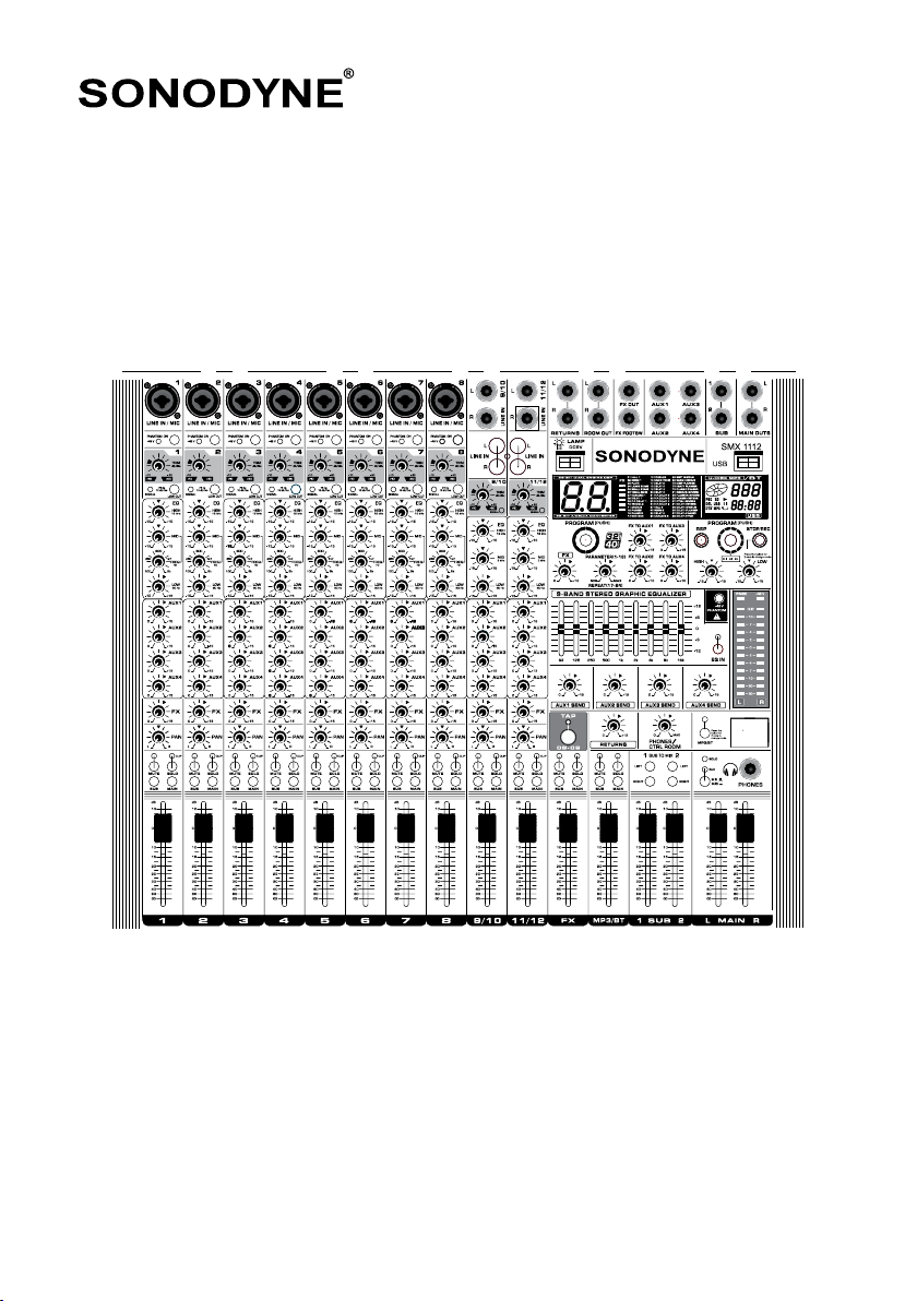
SMX SERIES
SMX 1112/ SMX 1116/ SMX 1124
small format analogue mixers I owners manual
www.sonodyne.com
SMX SERIES page 1
STATUTORY INFORMATION/ PRECAUTIONS
IMPORTANT SAFETY INSTRUCTIONS
1. Read and follow these instructions.
2. Do not use this apparatus near water.
3. Clean with dry cloth only.
4. Do not block any ventilation openings. Install in accordance with the manufacturer’s instructions.
5. Do not install near any heat sources such as radiators, stoves, or other apparatus (including amplifiers)
that produce heat.
6. Do not defeat the safety purpose of the polarized or grounding-type plug. A grounding type plug has two
poles and a third grounding pole. The thick pole is provided for your safety. If the provided plug does not
fit into your outlet, consult an electrician for replacement of the outlet
7. Protect the power cord from being walked on or pinched particularly at plugs, convenience receptacles,
and the point where they exit from the apparatus.
8. The apparatus shall be connected to a MAINS socket outlet with a protective earthing connection.
9. Unplug this apparatus during lightning storms or when unused for long periods of time.
10. Refer all servicing to qualified service personnel. Servicing is required when the apparatus has been
damaged in any way, such as power-supply cord or plug is damaged, liquid has been spilled or objects
have fallen into the apparatus, the apparatus has been exposed to rain or moisture, does not operate
normally, or has been dropped.
The lightning flash with arrowhead symbol within an equilateral triangle is intended to alert
the user to the presence of “un-insulated dangerous voltage” within the product’s enclosure
that may be of sufficient magnitude to constitute a risk of electric shock.
The exclamation point within an equilateral triangle is intended to alert the user to the
presence of important operating and maintenance (servicing) instructions in the literature
accompanying the product.
WARNING:
TO REDUCE THE RISK OF FIRE OR ELECTRIC SHOCK, DO NOT EXPOSE THIS APPARATUS TO RAIN OR MOISTURE
BEFORE YOU GET STARTED
Your mixing console was carefully packed in the factory to guarantee safe transport. Nevertheless, we
recommend that you carefully examine the packaging and its contents for any signs of physical damage,
which may have occurred during transit.
If the unit is damaged, please notify your dealer and the shipping company immediately, otherwise claims for
damage or replacement may not be granted.

INITIAL OPERATION
• Besurethatthereisenoughspacearoundtheunitforcoolingpurposesandtoavoidover-heating.
Do not place your mixing console on high-temperature devices such as radiators or power amps.
• Theconsoleisconnectedtothemainssupplyviathesuppliedcable.
• Theconsolemeetstherequiredsafetystandards.
• Blownfusesmustbereplacedonlybyfusesofthesametypeandrating.
• Notethatallunitsmustbeproperlygrounded.Foryourownsafety,youshouldneverremoveanyground
connectors from electrical devices or power cables, or render them inoperative.
CONNECTORS
XLR-type connectors are wired as follows (IEC60268 standard): pin 1: ground, pin 2: hot (+), pin 3: cold (-)
MAIN FEATURES
HIGH-QUALITY OPERATIONAL AMPLIFIERS
Mono input channels are equipped with discrete microphone preamplifiers. The pre amplifier features circuit
used in high-end audio devices. This circuit uses multi-stage amplifiers to ensure high current and low
impedance, for an audio texture with crispness and richness in the low and mid frequencies.
Combined with the specially-designed operational amp, the overall result is full-bodied reproduction of low
frequencies as well as sustained high frequencies. Input channels feature combo jacks, which can accept
both XLR and TRS connectors. In addition, Trim Control allows line level input, to accommodate a wide variety
of instruments
BUILT-INUNIVERSALSWITCHINGPOWERSUPPLY
The SMX Series features a universal switching power supply. This power supply supports input voltages of
100Vto240V,forstableoperationeveninenvironmentswherepowervoltageuctuateseasily.AnACinlet
allows simple installation in environments where portability is required, as well as when mounting the mixing
console in a rack
32 HIGH-QUALITY DIGITAL EFFECTS
The SMX models feature 99 built-in effects that are based on DSP FX
ADDED FEATURES
• USBplayback
• USBRecording
• GlobalEqualizer
• TapDelay
• BluetoothPlayback
SMX SERIES page 2
INITIAL OPERATION/ MAIN FEATURES

CONNECTION DIAGRAM
SMX SERIES page 3
AMPLIFIER
LIVE
INSTRUMENTS KEYBOARD
MICROPHONES
HEADPHONE
ACTIVE
SPEAKERS
STAGE MONITOR
CD PLAYER

CONNECTION DIAGRAM
SMX SERIES page 4
39
40
41
42
43
44
46
47
48
50
51
49
45
1
15 16 35 36 37 38
2
3
24
25
26
27
28
29
30
31
32
33
34
4
5
6
7
8
9
10
11
12
13
14
17 18 19 21 22 2320

SWITCHES
SMX SERIES page 5
1. MIC INPUT JACKS: These are balanced XLR-type microphone input jacks.
(1: Ground; 2: Hot; 3: Cold)
2. LINE INPUT JACKS (mono channels): These are balanced TRS phone-jack line inputs. (T: Hot; R:
Cold; S: Ground). You can connect either balanced or unbalanced phone plugs to these jacks
3. 48V INDICATOR: Thered“48VLEDlightsupwhenphantompowerisswitchedon.Phantom
power is required to operate condenser microphones
4. PHANTOM +48 V SWITCH: This switch toggles phantom power on and off. When the switch
isonthemixersupplies+48VphantompowertoallchannelsthathaveXLRmicinputjacks
5. TRIM CONTROL: Adjusts the input signal level. To get the best balance between the S/N ratio
and the dynamic range adjust the gain, so that the PEAK indicator (9) lights only occasionally and
briefly on the highest input transients. The -60 to +10 scale is the MIC input adjustment range. The
-40 to +10 scale is the LINE input adjustment range
6. LOW CUT SWITCH: This switch toggles the HPF on or off. The HPF cuts frequencies below
75Hz
7. SIGNAL LED: This is a signal presence indicator which glows when signal is applied to input
8. EQUALISER (High, Mid and Low): This three-band equalizer adjusts the high, mid and low
frequency bands of the corresponding channel. Setting the knob to the "0" position produces a flat
response in the corresponding band. Turning the knob to the right boosts the corresponding frequency
band, while turning to the left attenuates the band. The center frequency of the mid equalizer can be
changed with the help of a frequency control which can be varied continuously from 100Hz to 8kHz
9. AUX CONTROL: Monitor and effects busses (AUX sends) source their signals via a control from
one or more channels and sum these signals to a so-called bus. This bus signal is sent to an aux send
connector (for monitoring applications: MON OUT) and then routed, for example, to an active monitor
speaker or external effects device. In the latter case, the effects return can then be brought back into
the console via the aux return connectors. All monitor and effects busses are mono and tapped into
postEQofferingamplicationofupto+15dB
10. FX CONTROL: The aux send marked FX offers a direct route to the built-in effects processor and
is therefore post-fader and post-mute
11. PAN CONTROL: The PAN control determines the position of the channel signal within the stereo
image. When working with subgroups, you can use the PAN control to assign the signal to just one
output, which gives you additional flexibility in recording situations. For example, when routing to
subgroups 3 and 4, panning hard left will route the signal to group output 3 only, and panning hard
right will route to group output 4 only

SWITCHES
SMX SERIES page 6
12. MUTE LED: The MUTE LED indicates a muted channel.
MUTE Switch: Pressing this switch mutes the corresponding channel.
CLIP LED: The PEAK LED lights up when the input signal is driven too high. If this happens, back off
the TRIM control and, if necessary, check the setting of the channel EQ.
SOLO Switch: The SOLO switch is used to route the channel signal to the solo bus (Solo In Place) or
to the PFL bus (Pre Fader Listen). This enables you to listen to a channel signal without affecting the
main output signal. The signal you hear is taken either before the pan control (PFL, mono) or after the
pan and channel fader (Solo, stereo)
13. SUB SWITCHassignstheoutputofthecorrespondingchanneltotheSUBbus
14. MAIN SWITCH assigns the output of the corresponding channel to the MAIN bus
15. CHANNEL FADER adjusts the level of the corresponding mono channel. Use these faders to
adjust the balance between the various channels
16. CHANNEL FADER: The function of this is same as the channel fader of mono channels
17. STEREO AUX RETURNS JACKS: The STEREO AUX RETURN jacks generally serve as the
return for the effects mix ( created using the post-fader aux sends ) by connecting the output of an
external effects device. If only the left jack is connected, the AUX RETURN is automatically switched to
mono
18. CONTROL ROOM OUT JACKS: The control room output is normally connected to the
monitoring system in the control room and carries the stereo mix or, when selected, the solo signals
19. FX OUT JACKS: The FX OUT jack should be used when hooking up a monitor power amp or
active monitor speaker system. The relevant FX path should be set pre-fader
20. FX FOOT SW JACK: Connect a standard foot switch to the foot switch jack and use this to
switch the effects processor on and off. A light at the bottom of the display indicates whether the
effects processor has been muted by the foot switch
21. AUX SEND JACK: The AUX SEND jack carries the master aux mix(from the channel's AUX
controls)
22. SUB OUT (1 - 2) JACKS:Theseimpedance-balanced*TRSphonejacksoutputtheSUB1/2
signals. Use these jacks to connect to the input jacks of an multi-track recorder, external mixer, or
other such device.

SMX SERIES page 7
23. MAIN OUT (L, R) JACKS: These jacks deliver the mixer's stereo output. You can use these
jacks, for example, to connect to the power amplifier driving your main speakers.
24. USB DC5V CONNECTOR: ThisisaUSB-Atypeconnectortopowera5VDClamp
25. EFFECTS DISPLAY: There are 99 different types of Effect each denoted by a number printed on
the panel. This number is shown by the display
26. PROGRAM DIAL (JOG): You can select the Effect preset by turning the PROGRAM control. The
display flashes with the number of the current preset. To recall the selected preset, press the button;
the flashing stops. You can also recall the selected preset with the foot switch
27. FX CONTROL THE AUX SEND (FX) JACK carries the master aux mix (from the channel's
FX controls). You can connect this to an external effects device to process the FX bus. The processed
signal can then be brought from the Effects device back into the STEREO AUX RETURN jacks
28. REPEAT CONTROL adjusts the parameter (depth, speed, etc.) for the selected effect. The last
value used with each effect type is saved
29. FX TO AUX CONTROL: This controls the level of Effect to AUX1 AUX2 AUX3 AUX4
30. 9-BAND STEREO GRAPHIC EQUALIZER: This stereo graphic equalizer allows you to
tailor the sound to the room acoustics (defeatable)
31. AUX SEND CONTROL Use this fader to control the signal level at AUX output jack
32. STEREO AUX RETURN1 Control Adjusts the level at which the signal received at the RETURN
jacks (L (MONO) and R) is sent to the STEREO L/R bus.
33. TAP SWITCH: Press this switch to change the repeat time. For short repeat time, press rapidly, for
longer repeat time, press slowly
34. PHONES/CTRL ROOM CONTROL: Use this control to adjust the control room output level
and the headphones volume.
35. FX SEND FADER: This is the master control for the Effects level.
36. MP3/BT FADERadjuststhelevelofMP3/BT.
37. SUB (1-4) FADERadjuststhesignallevelsenttotheSUBOUT(1to4)jacks.
38. MAIN MIX FADER: This is the master level control for the MAIN OUTS.
SWITCHES
SMX SERIES page 8
39. MP3 USB JACK: Connect a flash drive to this socket for playing MP3 audio files. This is a host
USBplayer.
40. MP3 DISPLAY: Shows various information about audio files being played like track number, name
of the track, etc.
41. MP3 SWITCHES:
• STOP/REC:TorecordtoUSBashdrive,presstheSTOP/RECswitchfor2secondsandrecording
will start. Press again the STOP/REC for 2 seconds to STOP recording. File will be automatically
savedintheUSBashdrive.
• PLAYJOGSwitch:Presstheswitchtopauseorplaytrack.
Rotate clockwise to select next track shown in display
Rotate anticlockwise to select previous track
YoucanselecttheMp3tracksbyturningtheJOGSwitch.
• ProgramDial:DisplaystheMODE:USBPlaybackwithTracks
USBRecording
Bluetooth
• Repeatswitch:Pressthisswitchtorepeatalltracksorasingletrack.
42. MP3 EQUALISER: This two-band equalizer allows you to adjust the tone control of the MP3
player.
43. PHANTOM: +48 V SWITCH: This (global) switch toggles phantom power on and off. When the
switchisonthemixersupplies+48VphantompowertoallchannelsthathaveXLRmicinputjacks.
44. 48V INDICATOR: Thered“48VLED”lightsupwhenphantompowerisswitchedon.Phantom
power is required to operate condenser microphones.
45. POWER INDICATOR: This indicator lights when power to the mixer is switched on.
46. LEVEL METER: Shows the level of signal. The “0” segment corresponds to the nominal output
level. The PEAK indicator lights when the output reaches the clipping level..
47. EQ IN SWITCH: Use this switch to activate the graphic equalizer.
48. BT: Press SWITCH for two seconds, the Signal LED will blink.
Usingmobilephoneortabletorpc,gototheBTdevicelistandsearchforMIXER-01topair.
Blinkingstopswhendeviceispared.
PresstheSWITCHagainfor2sectodisconnectBT.
RestartBTtopairtoanothermobilephoneortabletPC.
49. SUB TO MAIN SWITCH:Ifthisswitchison,themixersendsthesignalsprocessedbytheSUB
faders onto the stereo bus.
SWITCHES

SMX SERIES page 9
52. FUSE HOLDER/IEC MAINS RECEPTACLE: The console is connected to the mains
viathecablesupplied,whichmeetstherequiredsafetystandards.Blownfusesmustonlybereplaced
by fuses of the same type and rating. The mains connection is made via a cable with IEC mains
connector. An appropriate mains cable is supplied with the equipment.
53. POWER SWITCH: Use the POWER switch to turn on the mixing console. The POWER switch
should always be in the “Off” position when you are about to connect your unit to the mains. To
disconnect the unit from the mains, pull out the main cord plug. When installing the product, ensure
that the plug is easily accessible.
54. GND CONTACT: GND in order to avoid leakage.
55. CONTROL ROOM OUT JACKS: The control room output is normally connected to the
monitoring system in the control room and carries the stereo mix or, when selected, the solo signals.
SWITCHES
50. PHONES JACK: Connect a pair of headphones to this TRS phone-type output jack.
51. SWITCH HEADPHONESbetweenMIXandSUBchannel.
52
55
53 54
CABLE CONNECTIONS
SMX SERIES page 10
Theillustrationsbelowshowthewiringofthesecables.Besuretouseonlyhigh-gradecables.
FOOT SWITCH CONNECTOR
INPUT OUTPUT
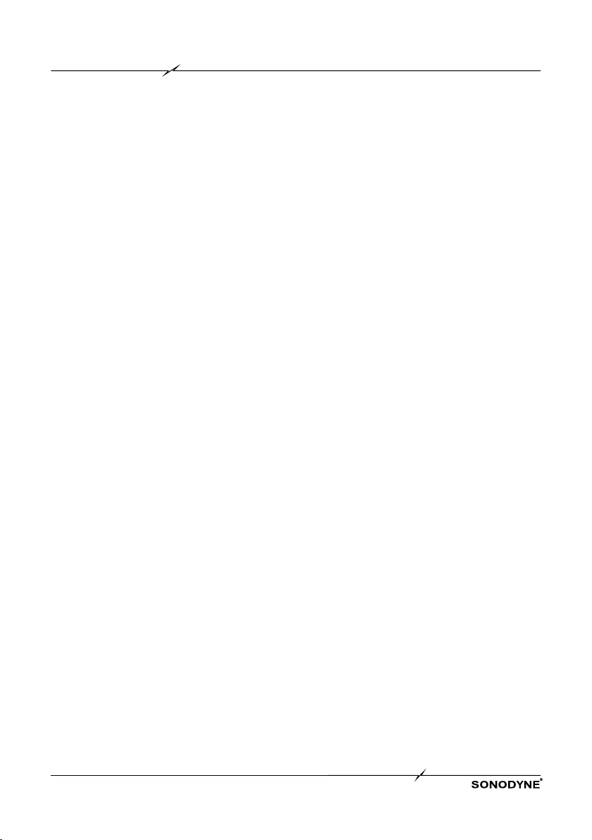
BALANCEDUSEWITHXLRCONNECTORS
For unbalanced use, PIN 1 & PIN 3 have to be bridged
1 = Ground/ Sleeve
2 = Hot (+ve)
3 = Cold (-ve)
XLR CONNECTIONS
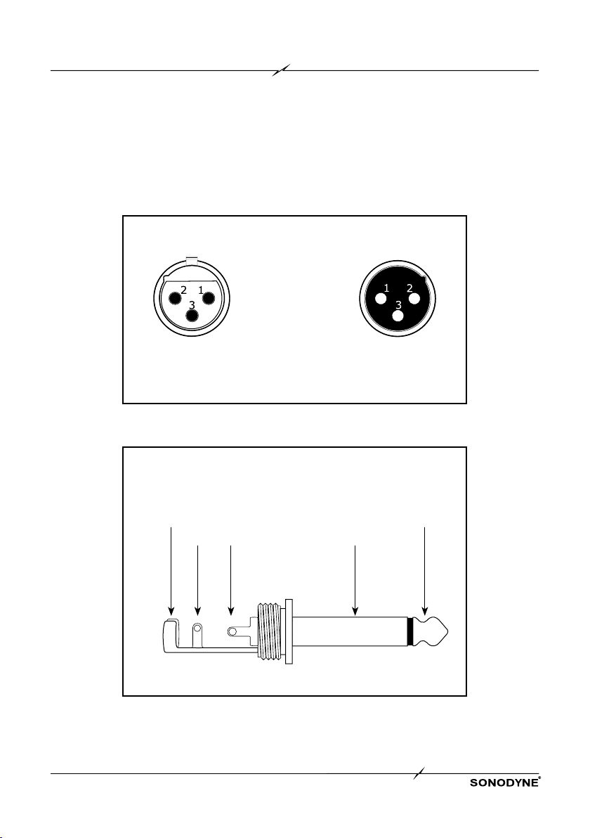
1/4" TS FOOT SWITCH CONNECTOR
Strain Relief Clamp Sleeve
Pole 1/ground
Tip
Pole 2
Sleeve Tip
The foot switch connects both poles momentarily

SMX SERIES page 11
AUDIO CONNECTIONS
Use commercial RCA cables to wire the 2-track inputs and outputs.
You can also connect unbalanced devices to the balanced input/outputs. Use either mono plugs, or use
stereo plugs to link the ring and shaft (or pins 1&3 in the case of XLR connectors).
CAUTION! You must never use unbalanced XLR connectors (PIN 1 and 3 connected) at the MIC input
jacks if you want to use the phantom power supply.
6.3: 1/4" MONO PLUG INSERT SEND RETURN 1/4" TRS CONNECTOR
Strain Relief
Clamp
Strain Relief
Clamp
Sleeve
(ground/ shield)
Sleeve
(ground/ shield)
Ring
return (in)
Tip
(signal)
Tip
send (out)
Sleeve Sleeve
Ring
Tip
Tip
Unbalanced 1/4" TRS connector
Connect the insert send with the input and the
insert return with the output of the effects device
BALANCED1/4"TRSCONNECTOR
Strain Relief
Clamp Sleeve
(ground/ shield)
Ring
cold (-ve)
Tip
hot (+ve)
Sleeve
RingTip
For connection of balanced and unbalanced plugs,
ring and sleeve have to be bridged at the stereo plug
1/4" TRS HEADPHONE CONNECTOR
Strain Relief
Clamp Sleeve
(ground/ shield)
Ring
right signal
Tip
left signal
Sleeve
RingTip

SMX SERIES page 12
Power does not • Isthemixerconnectedtoanindependentpowersource(generator,
come on etc.) or a power strip with switches?
Check that the power of that device is turned on.
No output • Areexternalinstruments(includingmicrophones)andspeakers
connected correctly?
• Areyourcablesshorted?
• Arethe[GAIN]knobsforeachchannel,channelfaders,[STEREO]
masterfader,and[GROUP]fadersadjustedtoappropriatelevels?
• Arethebusassignswitchessetappropriately?
No output from the • Arethe[ON]switchand[ST]switchforthechannelsyouareusing
[STEREO OUT] jack turned on?
• Isthe[STEREO]master[ON]switchturnedon?
No output from the • Arethe[SENDMASTER]knobsand[AUX1–4]foreachchannelset
[SEND (AUX1 – 4)] jacks appropriately?
• Arethe[ON]switchesforthechannelsyouareusingturnedon?
No output from the • AretheSOLO[PFL]switchesforthechannelsyouarenotusing
[PHONES] jack turnedon?TurntheSOLO[PFL]switchesoff.
Sound is low, distorted, • Isthemicrophoneconnectedtoa[MIC]jackora[MIC/LINE]jack?
or noisy • Whenusingacondensermicrophone,isthe[PHANTOM+48V]
switch turned on?
• Isthe[PAD]switchon?Turnthisswitchoffforsourceswithlow
output levels, such as microphones.
• Istheoutputsignallevelfortheinstrumentconnectedtothemixer
appropriate?
• Whenconnectinganinstrumentwithanoutputlevelof+4dBu,
either turn down the TRIM control on a mono input channel or use a
stereo input channel.
• WhereaninputchannelprovidesbothaXLRinputjackandaphone
input jack, or a phone input jack and an RCA pin jack, are there
connections made at both jacks? Use only one of these jacks.
• Arethe[GAIN]knobsforeachchannel,channelfaders,[STEREO]
masterfader,and[GROUP]fad-ersadjustedtoappropriatelevels?
• Areeffectorcompressorlevelstoohigh?Usethe[FX]knob,[FX
RTN]fader,[FXRTNLEVEL]knob,and[COMP]knobtolowertheir
levels.
TROUBLESHOOTING
SMX SERIES page 13
TROUBLESHOOTING
Effects cannot be • Arethe[FX]knobsforeachchanneladjustedtoappropriatelevels?
applied • Isthe[ON]buttonfor[FXRTN]turnedon?
• Arethe[PARAMETER]knoband[FXRTN]faderadjustedto
appropriate levels?
• Isthe[FXRTN]busassignswitchsetappropriately?
• Ifexternaleffectsareconnectedtothe[SEND(AUX1–4)]jacks,are
the[AUX1–4]knobsfor[SENDMASTER]setappropriately?
Voices are not clear • Isthe[HPF]switchturnedon?
• Istheequalizer([HIGH]/[MID]/[LOW])adjustedappropriately?
No output from • Arepoweredspeakersconnectedtothe[MONITOROUT]jacks?
MONITOR OUT Usethe[MONITORLEVEL]knobtoadjustthesignaloutputfromthe
[MONITOROUT]jacks.
Left and right levels are • Is[PAN]settothecenter?Ifpannedtothecenter,tryreversingthe
different for a stereo left and right input connections. If, after switching the left and right
signal input connections, the side with the low volume level also switches, check
the instrument or device that is the source of the signal.
• Areyouusingthesametypeofcabletoconnectboththeleftand
right input signals? Cables with built-in resistors will attenuate the
signal.
The sound level is • Isthecompressorlevelsettoohigh?UsetheTRIMknobtolowerthe
unstable and inconsistent level
SPECIFICATIONS
SMX 1112 SMX1116 SMX1124
INPUT MONO (MIC/LINE) 8 12 20
INPUT STEREO 2 2 2
OUTPUT MAIN 2 2 2
OUTPUT AUX 4 4 4
OUTPUT GROUP 2 2 2
GRAPHIC EQ 9 band stereo, switchable
EQ HIGH Gain±15dB,Freq12kHzshelving
EQ MID Gain±15dB
Mono channels - Freq 100Hz ~ 3kHz peaking, Stereo channels - Freq 3kHz peaking
EQ LOW Gain±15dB,Freq80Hzshelving
LOW CUT 75Hz18dB/octave
EFFECTS 99 effects, DSP based
BT/USB PLAYBACK yes yes yes
RECORD TO USB yes yes yes
FADERS Individual channel, Effects master, MP3 master, Sub group master 1,2, Main L, R fader, 60mm
LEVEL METER 12- digit, peak-reading LED level meter
PHANTOM POWER Per mic ch/global
OTHER FEATURES PER
CHANNEL Mute,solo,low-cutandbus-assignswitchesMAIN,SUB)
MIC EIN, 50Ω SOURCE
RESISTANCE, 20Hz~
20kHz
-133dB
FREQ. RESPONSE +0, -1dB 10Hz ~ 90kHz
THD 0.004% A- weighted
SNR 110dB,A-weighted,+22dBgain
MAX OUTPUT LEVEL +22dBu
POWER REQUIREMENT 230VAC50Hz
POWER CONSUMPTION 50W 55W 60W
DIMENSION HxWxD (mm) 150 x 510 x 475 150 x 620 x 475 150 x 620 x 475
Due to continuous improvements, all specifications are subject to change
SMX SERIES page 14

A product of the Mukherjee Innovation Centre
SonodyneTechnologiesPvt.Ltd,98NBBlockENewAlipore,Kolkata700053,INDIA
Please visit us at www.sonodyne.com
This manual suits for next models
3
Table of contents


