InoTec CPS 220/48.1 Series Service manual

Sicherheitstechnik GmbH
Montage- und Betriebsanleitung
Zentralbatteriesystem
CPS 220 / 48.1 / J-SV / J-SKÜ
Mounting- and Operating Instructions
Central Battery System
CPS 220 / 48.1 / J-SV / J-SKÜ
Sicherheitstechnik GmbH


3
CPS 220/48.1/SV Montage- und Betriebsanleitung CPS 220/48.1/SV Mounting and Operating Instructions
Inhalt
1. Allgemeine Hinweise 6
1.1. Symbolerklärung 6
1.2. Haftung und Gewährleistung 6
1.3. Ersatzteile 6
1.4. Entsorgung 6
1.5. Fehlerbeseitigung 6
2. Sicherheitshinweise 7
2.1. Bedienungsanleitung 7
2.2. Reparaturen 7
3. Transport und Lagerung 7
3.1. Kontrolle bei Anlieferung 7
3.2. Lagerung 7
4. Produktbeschreibung 8
4.1 CPS 220 / 48.1, CPUS 220 / 48.1 8
4.1.1. Aufbau der CPS 220 / 48.1 10
4.2 CPUSB 220 / 48.1 / 6
CPUSB 220 / 48.1 / 16
CPUSB 220 / 48.1 / 32
CPUSB 220 / 48.1 / 48 13
5. Technische Daten 15
5.1. CPS 220 / 48.1 / ...
CPUS 220 / 48.1 / ... 15
5.2. CPUSB 220 / 48.1/ ... 18
6. Aufstellung, Anschluss 19
6.1.1. CPS 220 / 48.1 / ..., CPUS 220 / 48.1 / ...,
CPUSB 220 / 48.1 / ... 19
6.2. Batterie 20
6.2.1. 1 Batterieschrank mit 1 Strang
á 18 Blöcke 21
6.2.2. 2 Batterieschränke mit 1 Strang
á 18 Blöcke 21
6.2.3. 2 Batterieschränke mit 2 Strängen
á 18 Blöcke 22
6.2.4. Batteriemontage auf Batteriegestell 22
6.2.5. Batterieschränke 2000mm 22
6.3. Elektrischer Anschluss 23
6.3.1. Systemaufbau 23
6.3.2. CPS 220 / 48.1 ..., CPUS 220 / 48.1 ...,
CPUSB 220 / 48.1 ... 24
6.3.3. CPUSB 220 / 48.1/6 27
6.3.4 Zusätzliche Komponenten 28
6.3.4.1. RIF 5 28
6.3.4.2. Batteriemanagementsystem BCS 32
6.3.4.3. LSA 3 / LSA 8.1 36
6.3.4.4. Dreiphasenüberwachungen 39
6.3.4.5. LOMO 42
6.3.4.6. Fernmeldetableau - MTB 43
6.3.4.7. CPS-MTB 44
Contents
1. General information 6
1.1. Explanation of symbols 6
1.2. Liability and warranty 6
1.3. Spare parts 6
1.4. Disposal 6
1.5. Correction of faults 6
2. Safety instructions 7
2.1. Operating instructions 7
2.2. Repairs 7
3. Transport and storage 7
3.1. Examination on delivery 7
3.2. Storage 7
4. Product description 8
4.1 CPS 220/48.1, CPUS 220/48.1 8
4.1.1. Layout CPS 220/48.1 10
4.2 CPUSB 220 / 48.1 / 6
CPUSB 220 / 48.1 / 16
CPUSB 220 / 48.1 / 32
CPUSB 220 / 48.1 / 48 13
5. Technical data 15
5.1. CPS 220 / 48.1 / ...
CPUS 220 / 48.1 / ... 15
5.2. CPUSB 220 / 48.1 / ... 18
6. Assembly, connection 19
6.1.1. CPS 220 / 48.1 / ..., CPUS 220 / 48.1 / ...,
CPUSB 220 / 48.1 / ... 19
6.2. Battery 20
6.2.1. 1 battery cabinet with 1 battery set
18 blocks each 21
6.2.2. 2 battery cabinets with 1 battery set
18 blocks each 21
6.2.3. 2 battery cabinets with 2 battery sets
18 blocks each 22
6.2.4. Mounting on battery rack 22
6.2.5. 2000 mm battery cabinets 22
6.3. Electrical connection 23
6.3.1. System structure 23
6.3.2. CPS 220 / 48.1 ..., CPUS 220 / 48.1 ...,
CPUSB 220 / 48.1 ... 24
6.3.3. CPUSB 220/48.1/6 27
6.3.4. Additional components 28
6.3.4.1. RIF 5 28
6.3.4.2. Battery management system BCS 32
6.3.4.3. LSA 3/LSA 8.1 36
6.3.4.4. Three-phase monitors (DPÜs) 39
6.3.4.5. LOMO 42
6.3.4.6. Remote mimic panel — MTB 43
6.3.4.7. CPS-MTB 44

4
CPS 220/48.1/SV Montage- und Betriebsanleitung CPS 220/48.1/SV Mounting and Operating Instructions
4
6.3.4.8. INOWEB 45
6.3.4.9. Phasenauswahlschaltung - PAS 46
7. Inbetriebnahme 47
7.1 Überprüfung der Verbindungen 47
7.2 Isolationsmessung 47
7.3. Einschalten des Zentralbatteriesystems 48
7.4. Ausschalten des Zentralbatteriesystems 48
8. Programmierung des CPS 220-Systems mit
Standardsteuerteil 49
8.1. Allgemeines 49
8.2. Testmenü 50
8.2.1. Funktionstest starten 50
8.2.2. Betriebsdauertest starten 50
8.2.3. Learn-Mode 50
8.2.4. Tiefentladeschutz prüfen 51
8.2.5. Isolationstesteinrichtung prüfen 51
8.2.6. Funktionstest abbrechen 51
8.2.7. Betriebsdauertest abbrechen 52
8.3. Info 52
8.3.1. Geräteinformationen 52
8.3.2. Störungs Info 54
8.3.3. Prüfbuch 55
8.4. Programmierung 56
8.4.1. Datum und Uhrzeit 56
8.4.2. Programmierung 57
9. Programmierung des CPS 220 - Systems mit
Komfortsteuerteils 67
9.1. Allgemeines 67
9.1.1. Aktualisierung der SD- Karte 68
9.1.2. Hilfetexte 68
9.2. Funktionstest starten / abbrechen 69
9.3. Info-Menü - Abfrage von Informationen 69
9.3.1. Geräte Info 70
9.3.2. Prüfbuch 71
9.3.3. Störungsausdruck 71
9.3.4. Stromkreisinformationen 72
9.3.5. Batterie- Info 74
9.3.6. DPÜ- Info 75
9.3.7. Komponenten- Info 75
9.4. Programmierung des CPS 220 Systems 78
9.4.1. Geräte- Programmierung 79
9.4.2. Zielort 81
9.4.3. Platzbelegung 81
9.4.4. Stromkreisprogrammierung 81
9.4.5. DPÜ/B 84
9.4.6. Module 84
6.3.4.8. INOWEB 45
6.3.4.9. Phase selector switch — PAS 46
7. Commissioning 47
7.1. Checking the connections 47
7.2. Insulation measuring 47
7.3. Energising the central battery system 48
7.4. De-energise the central battery system 48
8. Programming the CPS 220 system with
standard controller 49
8.1. General 49
8.2. Test menu 50
8.2.1. Running a function test 50
8.2.2. Starting battery duration test 50
8.2.3. Learn mode 50
8.2.4. Checking deep discharge protection 51
8.2.5. Checking insulation testing device 51
8.2.6. Cancelling a function test 51
8.2.7. Cancelling battery duration test 52
8.3. Info 52
8.3.1. Device information 52
8.3.2. Failure info 54
8.3.3. Logbook 55
8.4. Programming 56
8.4.1. Date and time 56
8.4.2. Programming 57
9. Programming the CPS 220 system with
comfort controller 67
9.1. General 67
9.1.1. Updating the SD card 68
9.1.2. Help texts 68
9.2. Running/cancelling a function test 69
9.3. Info menu — Requesting information 69
9.3.1. Device info 70
9.3.2. Logbook 71
9.3.3. Failure printout 71
9.3.4. Circuit info 72
9.3.5. Battery info 74
9.3.6. DPÜ info 75
9.3.7. Component info 75
9.4. Programming the CPS 220 system 78
9.4.1. Device programming 79
9.4.2. Destination 81
9.4.3. Position assignment 81
9.4.4. Circuit programming 81
9.4.5. DPÜ/B 84
9.4.6. Modules 84

5
CPS 220/48.1/SV Montage- und Betriebsanleitung CPS 220/48.1/SV Mounting and Operating Instructions
9.5. Testmenü 88
9.5.1. Automatischer Funktionstest 89
9.5.2. Automatischer Betriebsdauertest 89
9.5.3. Learn Mode 89
9.5.3.1 Learn-Mode SKÜ-Stromkreise 89
9.5.4. Betriebsdauertest (BT) starten 90
9.5.5. ISO – Test 90
9.5.6. Tiefentladeschutz (TES) prüfen 90
9.6. Einstellungen 90
9.6.1. RTG-Adresse 91
9.6.2. Datum und Uhrzeit 91
9.6.3. USB 91
9.6.4. Netzwerkeinstellungen 94
9.7. INOWEB 94
9.7.1 Bedienung 95
9.7.2. Störungsausdruck 96
9.7.3. Externe Verknüpfungen 97
9.7.3.1. Einrichtung externer
Verknüpfungen 97
10. Prüfungen 99
10.1 Erstprüfungen 99
10.2. Wiederkehrende Prüfungen der
elektrischen Anlagen für Sicherheitszwecke 99
10.3. Batterieinspektion und –überwachung 100
10.4. Protokolle zu wiederkehrenden Prüfungen 101
Anhang 102
A. Dokumentation 102
B. Leitungslängen 102
C. Kundendienst 102
Prüfung auf Leuchtenfehler 102
Softwareversion 103
D. Software version 103
Index 104
9.5. Test menu 88
9.5.1. Automatic function test 89
9.5.2. Automatic battery duration test 89
9.5.3. Learn mode 89
9.5.3.1 Learn mode SKÜ circuits 89
9.5.4. Start battery duration test (DT) 90
9.5.5. ISO test 90
9.5.6. Test deep discharge protection (TES) 90
9.6. Settings 90
9.6.1. RTG address 91
9.6.2. Date and time 91
9.6.3. USB 91
9.6.4. Network settings 94
9.7. INOWEB 94
9.7.1 Operation 95
9.7.2. Failure printout 96
9.7.3. External links 96
9.7.3.1. Configuring external links 97
10. Tests 99
10.1 Initial tests 99
10.2. Recurring safety tests on electrical systems 99
10.3. Battery inspection and monitoring. 100
10.4. Protocols for repeat tests 101
Appendix 102
A. Documentation 102
B. wire lengths 102
C. Customer Service 102
Check for luminaire failures 102
Software version 103
D. Software version 103
Index 104
6
CPS 220/48.1/SV Montage- und Betriebsanleitung CPS 220/48.1/SV Mounting and Operating Instructions
6
1. General information
1.1. Explanation of symbols
This symbol highlights important information
in the mounting and operating instructions
that also concerns safety. Failure to follow
the instructions may result in physical injury
or breakage!
Instructions marked by a yellow icon provide
important information. Please read these very
carefully.
This icon provides additional information.
1.2. Liability and warranty
INOTEC does not accept any responsibility or liability
whatsoever for damage or consequential damage caused
by:
• Failure to operate devices according to their intended use
• Failure to follow instructions relating to safe operation
• The use of unauthorised or unsuitable components in
conjunction with the emergency lighting system
• Faulty installation
• Opening the device
1.3. Spare parts
Defective components must only be replaced with
original INOTEC spare parts. We cannot guarantee that
safety requirements are fully met if parts other than these
are used. No warranty, service or liability claims will be
acknowledged if unsuitable spare parts are used.
The use of defective spare parts may result in mal-
function or cause the system to fail entirely.
1.4. Disposal
Batteries and electronic components supplied by
INOTEC can be returned to INOTEC or should be
disposed of in accordance with the national guide-
lines and regulations governing the disposal of
used batteries and electronic components.
1.5. Correction of faults
Whenever a fault associated with connected lumi-
naires is corrected, a function test must be carried
out to reset the fault indication.
see 8.2.1. Running a function test on page 50
see 9.2. Running/cancelling a function test on page 69
1. Allgemeine Hinweise
1.1. Symbolerklärung
Sicherheitsrelevante Informationen sind durch
nebenstehendes Symbol gekennzeichnet. Eine
Nichtbefolgung der Anweisungen kann zu Per-
sonenschäden oder defektem Gerät führen!
Hinweise liefern wichtige Informationen und
sind mit einem gelben Symbol markiert. Bitte
lesen Sie diese sehr aufmerksam.
Dieses Symbol macht Sie auf zusätzliche Infor-
mationen aufmerksam.
1.2. Haftung und Gewährleistung
INOTEC übernimmt keine Gewährleistung oder Haftung
für Schäden oder Folgeschäden, die entstehen durch
• Nicht bestimmungsgemäßen Gebrauch
• Nichteinhaltung von Vorschriften für den sicheren
Betrieb
• Betrieb von nicht zugelassenen oder ungeeigneten
Komponenten am Notlichtsystem
• Bei fehlerhafter Installation
• Bei Eingriff in das Gerät
1.3. Ersatzteile
Defekte Bauteile dürfen nur gegen INOTEC-Original-
Ersatzteile ausgetauscht werden. Nur bei diesen Teilen
gewährleisten wir, dass Sie die Sicherheitsanforderungen
im vollen Umfang erfüllen. Garantie-, Service- und Haft-
pflichtansprüche erlöschen bei Verwendung nicht geeig-
neter Ersatzteile.
Der Einsatz von fehlerhaften Ersatzteilen kann zu
fehlerhaftem Betrieb oder einem nicht funktionie-
rendem System führen.
1.4. Entsorgung
Von INOTEC gelieferte Batterien und Elektronikbau-
teile können an INOTEC zurückgegeben werden
oder sind gemäß den nationalen Richtlinien und
Vorschriften für die Entsorgung von Alt-Batterien
und Elektronikbauteilen zu entsorgen.
1.5. Fehlerbeseitigung
Nach jeder Fehlerbeseitigung der angeschlossenen
Leuchten muss ein Funktionstest ausgelöst werden,
um den angezeigten Fehler zu löschen.
siehe 8.2.1. Funktionstest starten - Seite 50
siehe 9.2. Funktionstest starten / abbrechen - Seite 69

7
CPS 220/48.1/SV Montage- und Betriebsanleitung CPS 220/48.1/SV Mounting and Operating Instructions
2. Safety instructions
Installation should only be carried out by electri-
cians qualified and trained and their operators.
The device must not be used for anything other than its
intended purpose and only in a perfect and undamaged
condition.
When installing and operating this device, please follow
your national safety and accident prevention regulations
at all times.
Before carrying out any work on the device, in particular
when replacing components, always disconnect the sys-
tem from the power source (mains and battery)!
see 7. Commissioning on page 47
2.1. Operating instructions
Always read the mounting and operating instruc-
tions before installing and commissioning the
device. These instructions contain important infor-
mation on the safety, use and maintenance of the device,
and will protect you and prevent damage to the system.
2.2. Repairs
Any repairs or adjustments of the device must be
performed by persons authorized by INOTEC. Otherwise
the guarantee becomes invalid.
3. Transport and storage
3.1. Examination on delivery
Please examine the device carefully at the point of receipt
to ensure complete delivery and that no external damage
exists. Please inform the carrier immediately if there are
any signs of damage — we regret that we are unable to
acknowledge complaints submitted after this point.
3.2. Storage
Until assembly, please observe the following regarding
storage of the device:
• Do not store in the open air
• Do store in a dry, dust-free environment
The following applies to batteries that have already been
fitted:
• Batteries must not be stored for more than 3 months
without being charged
• If the mains supply is interrupted for an extended
period of time, the battery circuit must be disconnected
by removing the battery fuse in accordance with the
operating instructions
see 7. Commissioning on page 47
• Charge the batteries for at least 24 hours before carrying
out the initial function test
2. Sicherheitshinweise
Die Installation darf nur durch Elektrofachkräfte
und deren Betreiber erfolgen.
Das Gerät ist bestimmungsgemäß und nur im einwand-
freien, unbeschädigten Zustand zu betreiben.
Für die Installation und den Betrieb dieses Gerätes sind
die nationalen Sicherheits- und Unfallverhütungsvor-
schriften zu beachten.
Vor Arbeiten an dem Gerät, insbesondere beim Austausch
von Baugruppen, ist die Anlage spannungsfrei zu schal-
ten (Netz- und Batteriespannung)!
siehe 7. Inbetriebnahme - Seite 47
2.1. Bedienungsanleitung
Lesen Sie vor der Montage und Inbetriebnahme
die Montage- und Betriebsanleitung. Sie gibt wich-
tige Informationen für die Sicherheit, den
Gebrauch und die Wartung des Gerätes. Dadurch schüt-
zen Sie sich und verhindern Schäden am Gerät.
2.2. Reparaturen
Eventuelle Reparaturen oder Eingriffe dürfen
ausschließlich durch INOTEC autorisierte Personen
vorgenommen werden. Eingriffe durch andere Personen
führen zum Verlust der Gewährleistung.
3. Transport und Lagerung
3.1. Kontrolle bei Anlieferung
Überprüfen Sie das Gerät bei Anlieferung unverzüglich
auf Vollständigkeit und äußere Beschädigungen. Melden
Sie dem Spediteur offensichtliche Beschädigungen sofort,
da wir spätere Reklamationen nicht anerkennen.
3.2. Lagerung
Das Gerät ist bis zur Montage wie folgt zu lagern:
• Nicht im Freien aufbewahren
• Trocken und staubfrei lagern
Für die Batterien gilt:
• Batterien dürfen max. 3 Monate ohne Ladung gelagert
werden
• Bei längerer Unterbrechung der Netzversorgung muss
der Batteriekreis durch entfernen der Batteriesicherung
gemäß Betriebsanleitung freigeschaltet werden
siehe 7. Inbetriebnahme - Seite 47
• Vor der ersten Funktionsprüfung sind die Batterien min.
24 Stunden zu laden

8
CPS 220/48.1/SV Montage- und Betriebsanleitung CPS 220/48.1/SV Mounting and Operating Instructions
8
4. Produktbeschreibung
Das Zentralbatteriesystem CPS 220 / 48.1 ist ein batte-
riegestütztes Überwachungs- und Versorgungsgerät für
den Notlichtbetrieb von Sicherheits- und Rettungszei-
chenleuchten. Die im Gerät integrierte und patentierte
Jokertechnik ermöglicht den gleichzeitigen Betrieb von
Dauer- und Bereitschaftsleuchten an einem Stromkreis.
Eine modulare Aufbauweise und die Möglichkeit, das
System durch Unterstationen und BUS-Unterstationen
zu erweitern, bietet für jede Anforderung eine optimale
Lösung.
4.1 CPS 220 / 48.1, CPUS 220 / 48.1
Das Zentralbatteriegerät CPS 220 / 48.1 ist mit seiner
integrierten Ladeeinrichtung der Hauptbestandteil des
Zentralbatteriesystems. Aufbauend auf diesen Gerätetyp
kann durch Einsatz der Unterstation CPUS 220 / 48.1 die
maximal anschließbare Leistung entsprechend erhöht
werden.
Der Einsatz unterschiedlicher Stromkreismodule (mit 3A
und 6A), welche wahlweise innerhalb des Gerätes oder
auch extern angeordnet werden können, ermöglichen
für jede Anforderung eine optimale Lösung. Die Versor-
gung der externen Stromkreismodule erfolgt über eine
dreiadrige Netzleitung, eine gesicherte zweiadrige Bat-
terieleitung und eine dreiadrige Busleitung. Das Strom-
kreismodul schaltet bei Ausfall der Busleitung umgehend
in den sicheren Betrieb (BL Ein).
Die Schaltungsart für jeden einzelnen Stromkreis kann
über das integrierte Steuerteil frei programmiert werden:
• Dauerlicht
• Bereitschaftslicht
• Geschaltetes Dauerlicht
• Jokerbetrieb
• Geschalteter Jokerbetrieb
Ebenso ist für jeden Stromkreis die Überwachungsart
(Unüberwacht, Stromkreis-, Einzelleuchtenüberwachung)
frei programmierbar. An jedem Stromkreis können bis
zu 20 Leuchten angeschlossen und einzeln überwacht-
werden. In der maximalen Ausbaustufe überwacht das-
Steuerteil somit bei max. 96 Stromkreisen bis zu 1.920
Leuchten
Eine Kommunikation der Stromkreise mit den Leuchten
geschieht ohne eine zusätzliche Datenleitung. Bei Joker-
betrieb wird die Schaltungsart (Bereitschafts- oder Dau-
erlicht) an dem Leuchtenmodul über einen Mikroschalter
vergeben. Die entsprechende Leuchtenadresse wird an
den Adressschaltern des Moduls vergeben. Über einen
optionalen Senseeingang am Leuchtenmodul besteht die
Möglichkeit die Leuchten lokal zu schalten.
Die Bedienung der Zentralbatteriesysteme CPS 220 / 48.1
sowie der CPUS 220 / 48.1 erfolgt über das integrierte
Steuerteil. Je nach Anforderung kann zwischen einer Ver-
sion mit vierzeiligem Display für die Statusinformationen
oder einer Komfortversion mit 5,7´´ TFT-Grafik-Display
mit integrierter USB-Schnittstelle und Netzwerkanschluss
gewählt werden. Die Programmierung des Gerätesteuer-
teils kann einerseits am Steuerteil direkt erfolgen als auch
4. Product description
The central battery systems CPS 220/48.1 is a safety
device for monitoring and supplying emergency- and
safety-lighting. The patented ‘Joker’ technology inte-
grated into the device enables simultaneous operation of
maintained and non-maintained lighting on one circuit.
A modular structure and the option of expanding the
system with sub stations and BUS sub stations offer an
optimised solution for every requirement.
4.1 CPS 220/48.1, CPUS 220/48.1
The central battery device CPS 220/48.1 with its inte-
grated charging system, is the main component of
the central power system. The use of sub station CPUS
220/48.1 with these device types allows the maximum
connectable power to be increased accordingly.
The use of various circuit modules (with 3A and 6 A),
which can be arranged either within the device or exter-
nally, offers an optimised solution for every requirement.
The external circuit modules are supplied via a fused
three-wire supply lead and a three-wire BUS data line. If
the BUS data line fails, the circuit module switches to safe
mode (NM On) immediately.
The operation mode for each individual circuit can be
freely programmed via the integrated controller:
• Maintained lighting
• Non-maintained lighting
• Connected maintained lighting
• Joker operation
• Connected Joker operation
For each circuit, the type of monitoring (unmonitored, cir-
cuit monitoring, individual luminaire monitoring) can also
be programmed in accordance with your requirements.
Up to 20 luminaires can be connected to each circuit and
individually monitored. At the maximum expansion stage,
the controller thus monitors up to 1920 luminaires on a
maximum of 96 circuits.
The circuits communicate with the luminaires without an
additional data line. During joker operation, the opera-
tion mode (non-maintained or maintained lighting) is
assigned to the luminaire module via a microswitch.
The corresponding luminaire address is assigned to the
address switches of the module. An optional sense input
on the luminaire module enables the luminaires to be
switched locally.
The central battery systems CPS 220/48.1 and the CPUS
220/48.1, are operated via the integrated controller.
Depending on the requirements, there is a version with
a four-line display for the status information or a comfort
version with a 5.7" TFT graphic display, integrated USB
interface and network connection. The device control-
ler can be programmed either on the controller itself
or via optional PC software and INOSTICK for controller
with four-line display or USB-stick for TFT-controller. Each
controller provides the option of saving text information
on change-over devices, modules and luminaires. The
programmed configuration is stored in the non-volatile
memory and is retained even if the power supply system
fails.

9
CPS 220/48.1/SV Montage- und Betriebsanleitung CPS 220/48.1/SV Mounting and Operating Instructions
mittels optionaler PC-Software und INOSTICK für Steuer-
teil mit vierzeiligem Display oder USB-Stick für Steuerteil.
Jedes Steuerteil bietet die Möglichkeit, Textinformationen
zu Einschüben, Modulen und Leuchten zu speichern.
Die Programmierung wird im nichtflüchtigen Speicher
abgelegt und bleibt auch bei Ausfall der Spannungsver-
sorgung erhalten.
Jederzeit können manuelle Tests zur Überprüfung ausge-
löst werden. Ebenso sind automatische Tests zu frei pro-
grammierbaren Zeitpunkten möglich. Die Testergebnisse
und Statusänderungen werden im integrierten Prüfbuch
detailliert gespeichert und sind jederzeit abrufbar. Das
Prüfbuch ist im nicht-flüchtigen Speicher abgelegt und
somit bleiben die Einträge auch nach einem Spannungs-
ausfall erhalten.
Ein Meldemodul für potentialfreie Meldekontakte ist
standardmäßig im Zentralbatteriesystem eingebaut
und liefert bis zu fünf Statusinformationen (Betrieb,
Batteriebetrieb, Störung, Optional 1, Optional 2). Über
dieses Meldemodul kann das Zentralbatteriesystem
auch von zentraler Stelle blockiert werden. Bei Einsatz
eines MTBs erfolgt dieses über den im MTB integrierten
Schlüsselschalter.
Das Zentralbatteriesystem CPS 220 / 48.1 sowie die
Unterstation CPUS 220 / 48.1 können mit optionalen
Modulen um folgende Funktionen erweitert werden:
• Anschluss von Dreiphasenüberwachungen (DPÜ) zur
Überwachung des allgemeinen Versorgungsnetzes
bzw. dessen Unterverteilern. Bei Ausfall einer Phase
schaltet das Zentralbatteriesystem die Notbeleuchtung
ein. Der Anschluss bei der DPÜ ohne Busanbindung
erfolgt über eine 24 V Stromschleife, welche sowohl
auf Unterbrechung als auch (optional) auf Kurzschluss
überwacht wird. Die DPÜ/B mit Busanbindung kann
den Ausfall einer Phase über Stromschleife oder mittels
Busanbindung an das Zentralbatteriesystem melden. In
der Meldung an das Zentralbatteriesystem ist die DPÜ-
Adresse und ausgefallene Phase enthalten.
• Lichtschalterabfragemodule ermöglichen entsprechend
programmierte Stromkreise mittels Lichtschalter zu
schalten. Die Anbindung erfolgt über den dreiadrigen
Systembus. Die Zentralbatteriesysteme unterstützten
maximal 3 Stück LSA 8 mit 8 Schalteingängen und 8
Stück LSA 3 mit drei Schalteingängen. Die LSA-Module
sind in Versionen mit 24V- und 230V-Eingängen
verfügbar.
• Möglichkeit der zentralen Überwachung des Systems
mittels Netzwerk. Bei Zentralbatteriesystemen mit
Komfort-TFT-Steuerteil ist die InoWeb-Funktionalität
schon standardmäßig integriert.
Je nach Projektanforderung sind die
Zentralbatteriesysteme CPS 220 / 48.1 und die
CPUS 220 / 48.1 in unterschiedlichen Ausbaustufen
verfügbar:
CPS 220 / 48.1 / 5, CPS 220 / 48.1 / 11
Maximale Anschlussleistung von 5,5kW mit 5 Modulplät-
zen für bis zu 10 Stromkreise bzw. 11 Modulplätzen für
bis zu 22 Stromkreise. Keine Anschlussmöglichkeit für
externe Stromkreismodule.
Manual tests for checking can be activated at any time.
Automatic tests can also be run at freely programmable
times. The test results and status changes are detailed in
the integrated logbook and can be retrieved at any time.
The logbook is stored in the non-volatile memory, which
means that the entries are retained even after a power
failure.
A signalling module for volt-free signalling contacts is
built into the central battery system as standard and
delivers up to five status messages (operation, battery
operation, fault, option 1, option 2). Via this signalling
module, the central battery system can also be blocked
from a central position. If an MTB is used, this is done
using the key switch integrated into the MTB.
Optional modules can be used to enhance the central
battery systems CPS 220/48.1 as well as the sub sta-
tion CPUS 220/48.1, with the following functions:
• Connection of three-phase monitors (DPÜ) for
monitoring the general supply network and/or its sub-
distribution boards. Should one phase fail, the central
battery system switches on the emergency lighting.
The connection on the DPÜ without bus connection
is via a 24 V current loop, which is monitored for both
interruption and also (optionally) for short circuits. The
DPÜ/B with bus connection can report the failure of a
phase to the central battery system via current loop or
by bus connection. The message to the central battery
system contains the DPÜ address and failed phases.
• Light sequence switching modules allow programmed
circuits to be switched via light switches. The connection
is via the three-wire system bus. The central battery
system supports a maximum of 3 LSA 8 with 8 input
switches and 8 LSA 3 with three input switches. The
LSA modules are available in versions with 24 V and
230 V inputs.
• Option of monitoring the system centrally via the
network. On central battery systems with comfort
TFT controller, the INOWEB functionality is already
integrated as standard. An InoWeb module is available
as an option for the four-line controller.
Depending on project requirements, the central bat-
tery systems CPS 220/48.1 and CPUS 220/48.1 are
available in various expansion levels:
CPS 220 / 48.1 / 5, CPS 220 / 48.1 / 11
Maximum connected load of 5.5 kW with 5 module slots
for up to 10 circuits or 11 module slots for up to 22 cir-
cuits. No connection option for external circuit modules.

10
CPS 220/48.1/SV Montage- und Betriebsanleitung CPS 220/48.1/SV Mounting and Operating Instructions
10
CPS 220 / 48.1 / 16
Maximale Anschlussleistung 22kW mit 8 internen Modul-
plätzen für bis zu 16 Stromkreise und 24 externe Modul-
plätze für bis zu 48 Stromkreise. Ausführungen 1- und
3-phasig.
CPS 220 / 48.1 / 32
Maximale Anschlussleistung 22kW mit 16 internen
Modulplätzen für bis 32 Stromkreise und 24 externe
Modulplätze für bis zu 48 Stromkreise. Ausführung
3-phasig.
CPS 220 / 48.1 / 48
Maximale Anschlussleistung 22kW mit 24 internen
Modulplätzen für bis zu 48 Stromkreise und 24 externe
Modulplätze für bis zu 48 Stromkreise. Ausführung
3-phasig.
CPUS 220 / 48.1 / 5
Unterstation mit eigener Steuereinheit für maximal 5,5kW
ohne Ladeeinrichtung, mit 5 Modulplätzen für bis zu 10
Stromkreise. Keine Anschlussmöglichkeit für externe
Stromkreismodule
CPUS 220 / 48.1 / 16, CPUS 220 / 48.1 / 32,
CPUS 220 / 48.1 / 48
Unterstation mit eigener Steuereinheit, ohne Ladeeinrich-
tung. Ausführungen mit 8, 16 oder 24 internen Modul-
plätzen für bis zu 16, 32 oder 48 Stromkreisen und 24
externe Modulpätze für bis zu 48 Stromkreise.
Weitere Informtationen zu den unterschiedlichen Versio-
nen sind im Kapitel „Technische Daten“ zu finden.
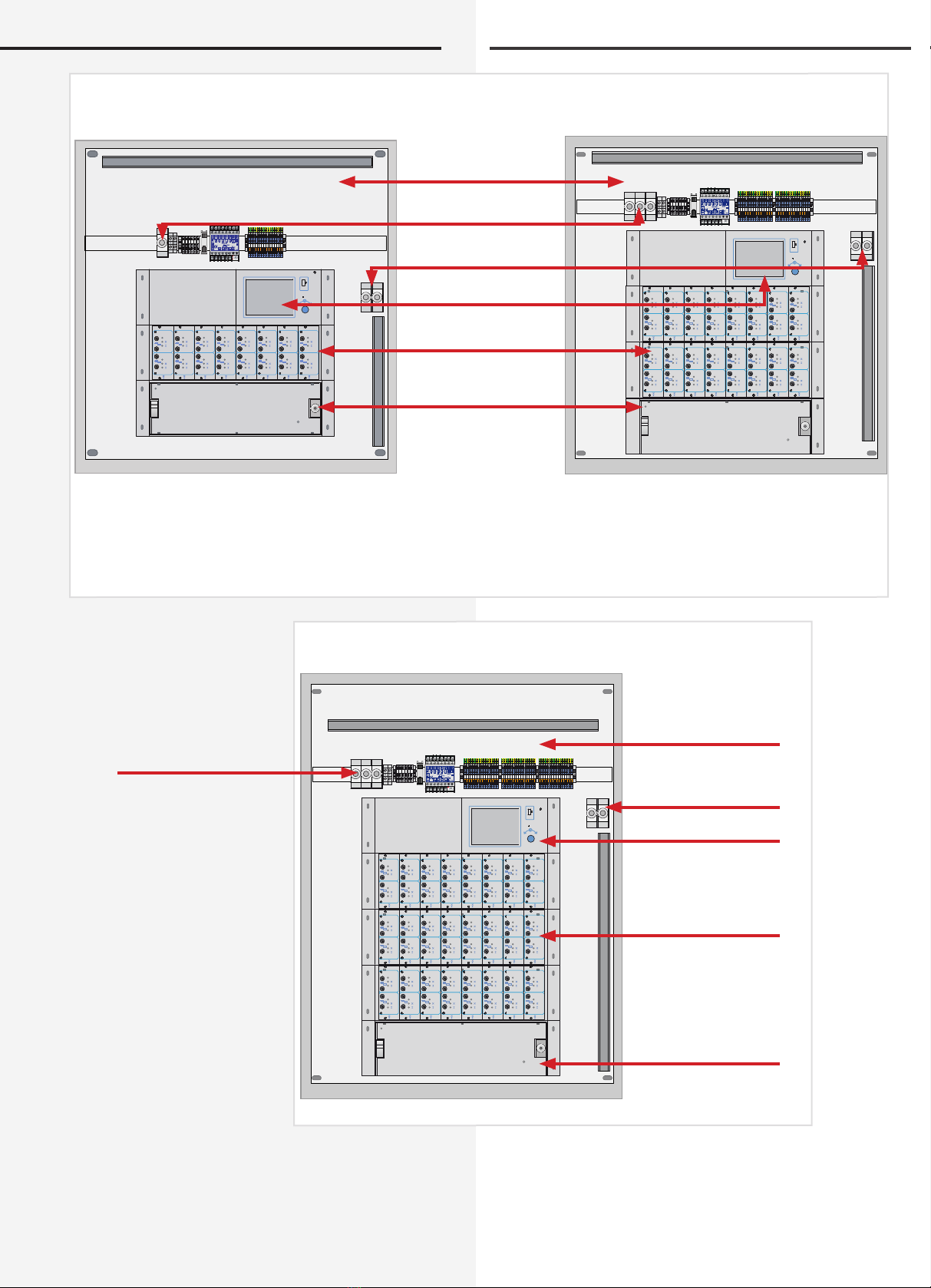
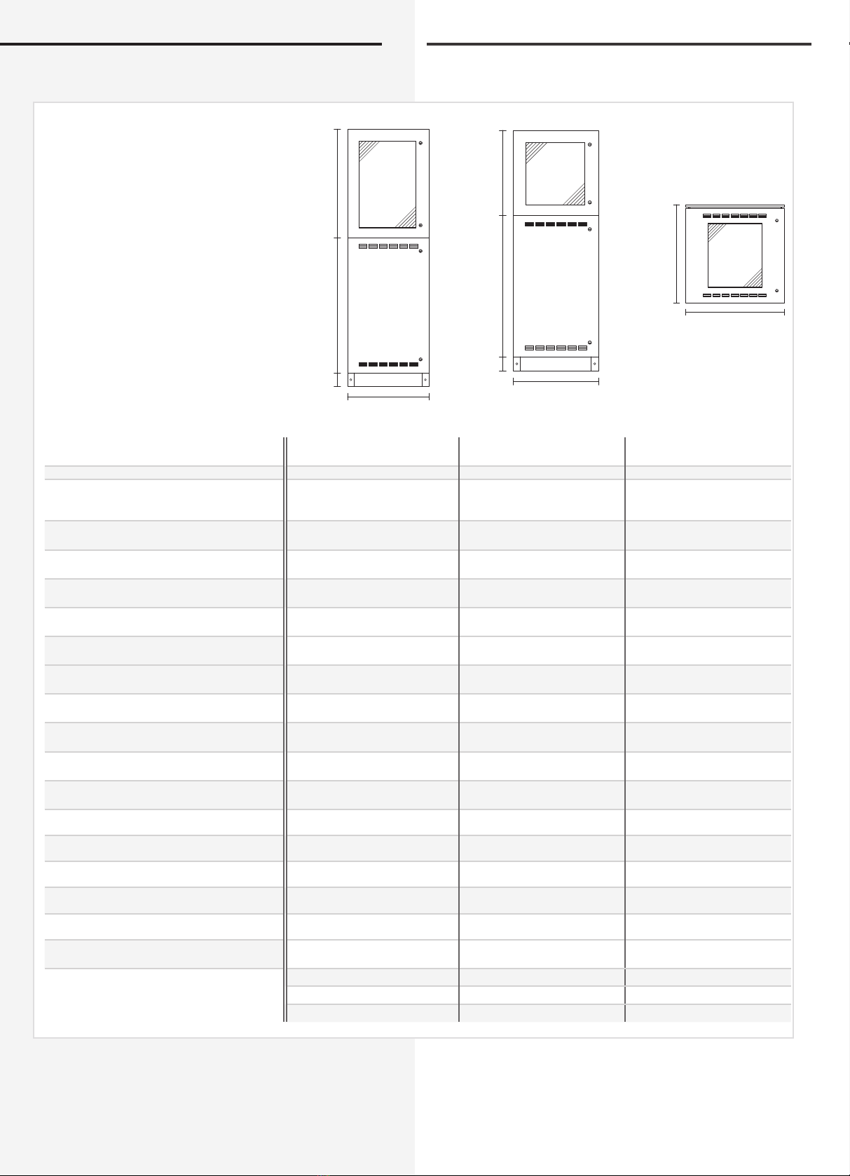
4.1.1. Aufbau der CPS 220 / 48.1
CPS 220 / 48.1 / 16
Maximum connected load 22 kW with 8 internal module
slots for up to 16 circuits and 24 external module slots for
up to 48 circuits. 1- and 3-phase designs.
CPS 220 / 48.1 / 32
Maximum connected load 22 kW with 16 internal module
slots for up to 32 circuits and 24 external module slots for
up to 48 circuits. 3-phase design.
CPS 220 / 48.1 / 48
Maximum connected load 22 kW with 24 internal module
slots for up to 48 circuits and 24 external module slots for
up to 48 circuits. 3-phase design.
CPUS 220 / 48.1 / 5
Substation with separate control unit for a maximum of
5.5 kW without charging system, with 5 module slots for
up to 10 circuits. No connection option for external circuit
modules.
CPUS 220 / 48.1 / 16, CPUS 220 / 48.1 / 32,
CPUS 220 / 48.1 / 48
Substation with separate control unit, without charging
system. Designs with 8, 16 or 24 internal module slots for
up to 16, 32 or 48 circuits and 24 external module slots for
up to 48 circuits.
Additional information on the various versions can be
found in the section “Technical Data”.
4.1.1. Layout CPS 220/20 and CPS 220/48.1
850 009
Netz
Ladeteil 220V/7,3A
Ein
10AT16AT
Batterie
SKE 2x3A
1
1000
5 AT
F
2
1000
5 AT
= BL/NM
= DL/NM
F
SKE 2x3A
1
1000
5 AT
F
2
1000
5 AT
= BL/NM
= DL/NM
F
SKE 2x3A
1
1000
5 AT
F
2
1000
5 AT
= BL/NM
= DL/NM
F
SKE 2x3A
1
1000
5 AT
F
2
1000
5 AT
= BL/NM
= DL/NM
F
SKE 2x3A
1
1000
5 AT
F
2
1000
5 AT
= BL/NM
= DL/NM
F
SKE 2x3A
1
1000
5 AT
F
2
1000
5 AT
= BL/NM
= DL/NM
F
SKE 2x3A
1
1000
5 AT
F
2
1000
5 AT
= BL/NM
= DL/NM
F
SKE 2x3A
1
1000
5 AT
F
2
1000
5 AT
= BL/NM
= DL/NM
F
SKE 2x3A
1
1000
5 AT
F
2
1000
5 AT
= BL/NM
= DL/NM
F
SKE 2x3A
1
1000
5 AT
F
2
1000
5 AT
= BL/NM
= DL/NM
F
SKE 2x3A
1
1000
5 AT
F
2
1000
5 AT
= BL/NM
= DL/NM
F
Betrieb
Operation
Batt.-Betrieb
Batt.-Operat.
Störung
Failure
Lade-Störung
Charge failure
INOTEC
Drucker / Printer
Reset
R T
Tastatur
Key-Board
1 2 3 4 5 6 7 8 9 1011 1213 1415 1617 1819 20
850 009
Netz
Ladeteil 220V/7,3A
Ein
10AT16AT
Batterie
SKE 2x3A
1
1000
5 AT
F
2
1000
5 AT
= BL/NM
= DL/NM
F
SKE 2x3A
1
1000
5 AT
F
2
1000
5 AT
= BL/NM
= DL/NM
F
SKE 2x3A
1
1000
5 AT
F
2
1000
5 AT
= BL/NM
= DL/NM
F
SKE 2x3A
1
1000
5 AT
F
2
1000
5 AT
= BL/NM
= DL/NM
F
SKE 2x3A
1
1000
5 AT
F
2
1000
5 AT
= BL/NM
= DL/NM
F
Betrieb
Operation
Batt.-Betrieb
Batt.-Operat.
Störung
Failure
Lade-Störung
Charge failure
INOTEC
Drucker / Printer
Reset
R T
Tastatur
Key-Board
1 2 3 4 5 6 7 8 9 1011 1213 1415 1617 1819 20
Stromkreismodule
Circuit modules
Steuerteil
Controller
Ladeteil
Charger
Batteriesicherungen
Battery fuses
CPS 220 / 48.1 / 5 CPS 220 / 48.1 / 11
Klemmen /Anschlußraum
Terminals
1 1
CPS 220/48.1/SV Montage- und Betriebsanleitung CPS 220/48.1/SV Mounting and Operating Instructions
! neue Ansichtszeichung CPS 220 / 48.1 / 5 !
850 009
Netz
Ladeteil 220V/7,5A
Ein
10AT16AT
Batterie
SKE 2x3A
1
1000
5 AT
F
2
1000
5 AT
= BL/NM
= DL/NM
F
SKE 2x3A
1
1000
5 AT
F
2
1000
5 AT
= BL/NM
= DL/NM
F
SKE 2x3A
1
1000
5 AT
F
2
1000
5 AT
= BL/NM
= DL/NM
F
SKE 2x3A
1
1000
5 AT
F
2
1000
5 AT
= BL/NM
= DL/NM
F
SKE 2x3A
1
1000
5 AT
F
2
1000
5 AT
= BL/NM
= DL/NM
F
SKE 2x3A
1
1000
5 AT
F
2
1000
5 AT
= BL/NM
= DL/NM
F
SKE 2x3A
1
1000
5 AT
F
2
1000
5 AT
= BL/NM
= DL/NM
F
SKE 2x3A
1
1000
5 AT
F
2
1000
5 AT
= BL/NM
= DL/NM
F
Menue
USB
SKE 2x3A
1
1000
5 AT
F
2
1000
5 AT
= BL/NM
= DL/NM
F
SKE 2x3A
1
1000
5 AT
F
2
1000
5 AT
= BL/NM
= DL/NM
F
SKE 2x3A
1
1000
5 AT
F
2
1000
5 AT
= BL/NM
= DL/NM
F
SKE 2x3A
1
1000
5 AT
F
2
1000
5 AT
= BL/NM
= DL/NM
F
SKE 2x3A
1
1000
5 AT
F
2
1000
5 AT
= BL/NM
= DL/NM
F
SKE 2x3A
1
1000
5 AT
F
2
1000
5 AT
= BL/NM
= DL/NM
F
SKE 2x3A
1
1000
5 AT
F
2
1000
5 AT
= BL/NM
= DL/NM
F
SKE 2x3A
1
1000
5 AT
F
2
1000
5 AT
= BL/NM
= DL/NM
F
850 009
Netz
Ladeteil 220V/7,5A
Ein
10AT16AT
Batterie
SKE 2x3A
1
1000
5 AT
F
2
1000
5 AT
= BL/NM
= DL/NM
F
SKE 2x3A
1
1000
5 AT
F
2
1000
5 AT
= BL/NM
= DL/NM
F
SKE 2x3A
1
1000
5 AT
F
2
1000
5 AT
= BL/NM
= DL/NM
F
SKE 2x3A
1
1000
5 AT
F
2
1000
5 AT
= BL/NM
= DL/NM
F
SKE 2x3A
1
1000
5 AT
F
2
1000
5 AT
= BL/NM
= DL/NM
F
SKE 2x3A
1
1000
5 AT
F
2
1000
5 AT
= BL/NM
= DL/NM
F
SKE 2x3A
1
1000
5 AT
F
2
1000
5 AT
= BL/NM
= DL/NM
F
SKE 2x3A
1
1000
5 AT
F
2
1000
5 AT
= BL/NM
= DL/NM
F
Menue
USB
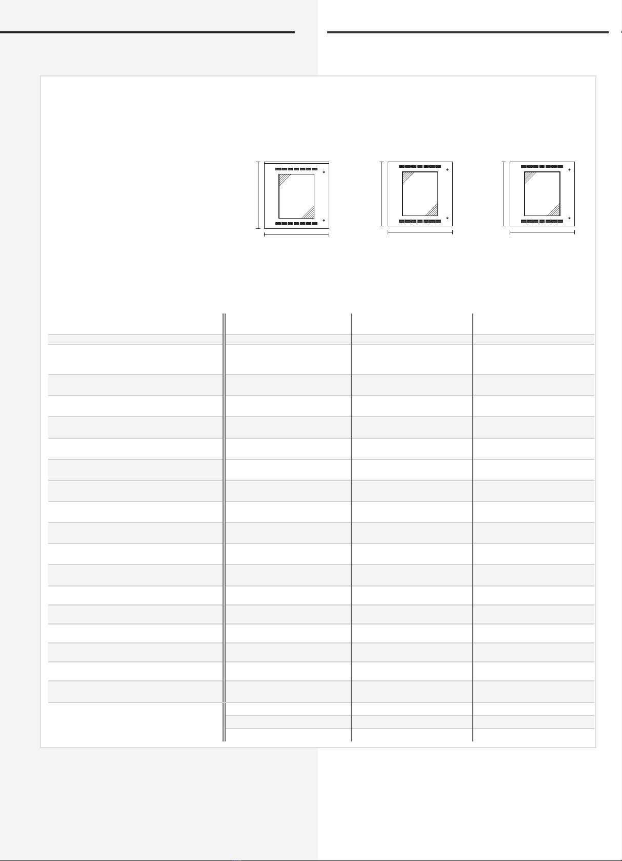
Batteriesicherungen
Battery fuses
Steuerteil
Controller
Ladeteil
Charger
Netzanschluß
Mains
Klemmen /Anschlußraum
Terminals
CPS 220 / 48.1 / 16 CPS 220 / 48.1 / 32
Stromkreismodule
Circuit modules
850 009
Netz
Ladeteil 220V/7,5A
Ein
10AT16AT
Batterie
SKE 2x3A
1
1000
5 AT
F
2
1000
5 AT
= BL/NM
= DL/NM
F
SKE 2x3A
1
1000
5 AT
F
2
1000
5 AT
= BL/NM
= DL/NM
F
SKE 2x3A
1
1000
5 AT
F
2
1000
5 AT
= BL/NM
= DL/NM
F
SKE 2x3A
1
1000
5 AT
F
2
1000
5 AT
= BL/NM
= DL/NM
F
SKE 2x3A
1
1000
5 AT
F
2
1000
5 AT
= BL/NM
= DL/NM
F
SKE 2x3A
1
1000
5 AT
F
2
1000
5 AT
= BL/NM
= DL/NM
F
SKE 2x3A
1
1000
5 AT
F
2
1000
5 AT
= BL/NM
= DL/NM
F
SKE 2x3A
1
1000
5 AT
F
2
1000
5 AT
= BL/NM
= DL/NM
F
SKE 2x3A
1
1000
5 AT
F
2
1000
5 AT
= BL/NM
= DL/NM
F
SKE 2x3A
1
1000
5 AT
F
2
1000
5 AT
= BL/NM
= DL/NM
F
SKE 2x3A
1
1000
5 AT
F
2
1000
5 AT
= BL/NM
= DL/NM
F
SKE 2x3A
1
1000
5 AT
F
2
1000
5 AT
= BL/NM
= DL/NM
F
SKE 2x3A
1
1000
5 AT
F
2
1000
5 AT
= BL/NM
= DL/NM
F
SKE 2x3A
1
1000
5 AT
F
2
1000
5 AT
= BL/NM
= DL/NM
F
SKE 2x3A
1
1000
5 AT
F
2
1000
5 AT
= BL/NM
= DL/NM
F
SKE 2x3A
1
1000
5 AT
F
2
1000
5 AT
= BL/NM
= DL/NM
F
Menue
USB
SKE 2x3A
1
1000
5 AT
F
2
1000
5 AT
= BL/NM
= DL/NM
F
SKE 2x3A
1
1000
5 AT
F
2
1000
5 AT
= BL/NM
= DL/NM
F
SKE 2x3A
1
1000
5 AT
F
2
1000
5 AT
= BL/NM
= DL/NM
F
SKE 2x3A
1
1000
5 AT
F
2
1000
5 AT
= BL/NM
= DL/NM
F
SKE 2x3A
1
1000
5 AT
F
2
1000
5 AT
= BL/NM
= DL/NM
F
SKE 2x3A
1
1000
5 AT
F
2
1000
5 AT
= BL/NM
= DL/NM
F
SKE 2x3A
1
1000
5 AT
F
2
1000
5 AT
= BL/NM
= DL/NM
F
SKE 2x3A
1
1000
5 AT
F
2
1000
5 AT
= BL/NM
= DL/NM
F
Klemmen Anschlußraum
Terminals
Steuerteil
Controller
Ladeteil
Charger
Batteriesicherungen
Battery fuses
CPS 220 / 48.1 / 48
Stromkreismodule
Circuit modules
Netzanschluß
Mains
12
CPS 220/48.1/SV Montage- und Betriebsanleitung CPS 220/48.1/SV Mounting and Operating Instructions
12
! nächste Seite Ansicht CPS 220 / 48.1 / 32, 48 (3-phasig) !
850 009
Menue
USB
SKE 2x3A
1
1000
5 AT
F
2
1000
5 AT
= BL/NM
= DL/NM
F
SKE 2x3A
1
1000
5 AT
F
2
1000
5 AT
= BL/NM
= DL/NM
F
SKE 2x3A
1
1000
5 AT
F
2
1000
5 AT
= BL/NM
= DL/NM
F
SKE 2x3A
1
1000
5 AT
F
2
1000
5 AT
= BL/NM
= DL/NM
F
SKE 2x3A
1
1000
5 AT
F
2
1000
5 AT
= BL/NM
= DL/NM
F
SKE 2x3A
1
1000
5 AT
F
2
1000
5 AT
= BL/NM
= DL/NM
F
SKE 2x3A
1
1000
5 AT
F
2
1000
5 AT
= BL/NM
= DL/NM
F
SKE 2x3A
1
1000
5 AT
F
2
1000
5 AT
= BL/NM
= DL/NM
F
850 009
SKE 2x3A
1
1000
5 AT
F
2
1000
5 AT
= BL/NM
= DL/NM
F
SKE 2x3A
1
1000
5 AT
F
2
1000
5 AT
= BL/NM
= DL/NM
F
SKE 2x3A
1
1000
5 AT
F
2
1000
5 AT
= BL/NM
= DL/NM
F
SKE 2x3A
1
1000
5 AT
F
2
1000
5 AT
= BL/NM
= DL/NM
F
SKE 2x3A
1
1000
5 AT
F
2
1000
5 AT
= BL/NM
= DL/NM
F
SKE 2x3A
1
1000
5 AT
F
2
1000
5 AT
= BL/NM
= DL/NM
F
SKE 2x3A
1
1000
5 AT
F
2
1000
5 AT
= BL/NM
= DL/NM
F
SKE 2x3A
1
1000
5 AT
F
2
1000
5 AT
= BL/NM
= DL/NM
F
SKE 2x3A
1
1000
5 AT
F
2
1000
5 AT
= BL/NM
= DL/NM
F
SKE 2x3A
1
1000
5 AT
F
2
1000
5 AT
= BL/NM
= DL/NM
F
SKE 2x3A
1
1000
5 AT
F
2
1000
5 AT
= BL/NM
= DL/NM
F
SKE 2x3A
1
1000
5 AT
F
2
1000
5 AT
= BL/NM
= DL/NM
F
SKE 2x3A
1
1000
5 AT
F
2
1000
5 AT
= BL/NM
= DL/NM
F
SKE 2x3A
1
1000
5 AT
F
2
1000
5 AT
= BL/NM
= DL/NM
F
SKE 2x3A
1
1000
5 AT
F
2
1000
5 AT
= BL/NM
= DL/NM
F
SKE 2x3A
1
1000
5 AT
F
2
1000
5 AT
= BL/NM
= DL/NM
F
Menue
USB
SKE 2x3A
1
1000
5 AT
F
2
1000
5 AT
= BL/NM
= DL/NM
F
SKE 2x3A
1
1000
5 AT
F
2
1000
5 AT
= BL/NM
= DL/NM
F
SKE 2x3A
1
1000
5 AT
F
2
1000
5 AT
= BL/NM
= DL/NM
F
SKE 2x3A
1
1000
5 AT
F
2
1000
5 AT
= BL/NM
= DL/NM
F
SKE 2x3A
1
1000
5 AT
F
2
1000
5 AT
= BL/NM
= DL/NM
F
SKE 2x3A
1
1000
5 AT
F
2
1000
5 AT
= BL/NM
= DL/NM
F
SKE 2x3A
1
1000
5 AT
F
2
1000
5 AT
= BL/NM
= DL/NM
F
SKE 2x3A
1
1000
5 AT
F
2
1000
5 AT
= BL/NM
= DL/NM
F
850 009
SKE 2x3A
1
1000
5 AT
F
2
1000
5 AT
= BL/NM
= DL/NM
F
SKE 2x3A
1
1000
5 AT
F
2
1000
5 AT
= BL/NM
= DL/NM
F
SKE 2x3A
1
1000
5 AT
F
2
1000
5 AT
= BL/NM
= DL/NM
F
SKE 2x3A
1
1000
5 AT
F
2
1000
5 AT
= BL/NM
= DL/NM
F
SKE 2x3A
1
1000
5 AT
F
2
1000
5 AT
= BL/NM
= DL/NM
F
Betrieb
Operation
Batt.-Betrieb
Batt.-Operat.
Störung
Failure
Lade-Störung
Charge failure
INOTEC
Drucker / Printer
Reset
R T
Tastatur
Key-Board
1 2 3 4 5 6 7 8 9 1011 1213 1415 1617 1819 20
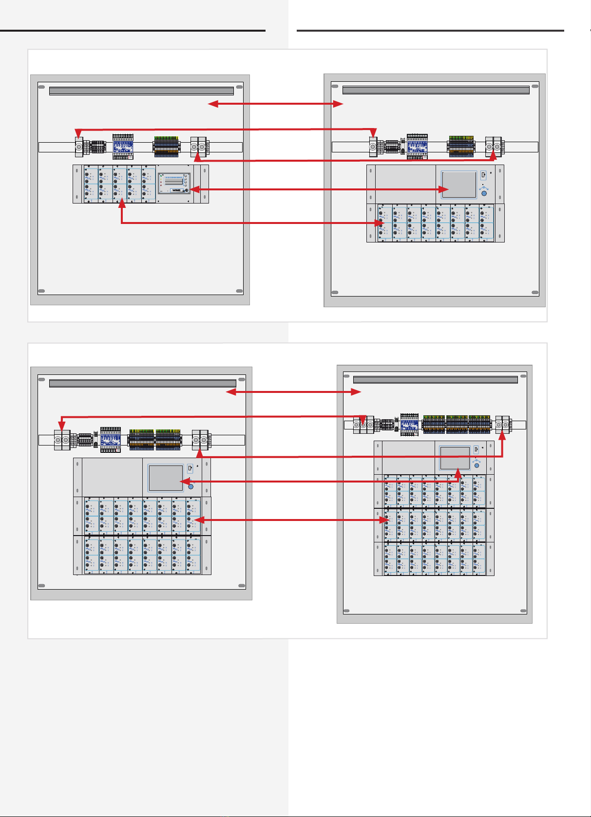
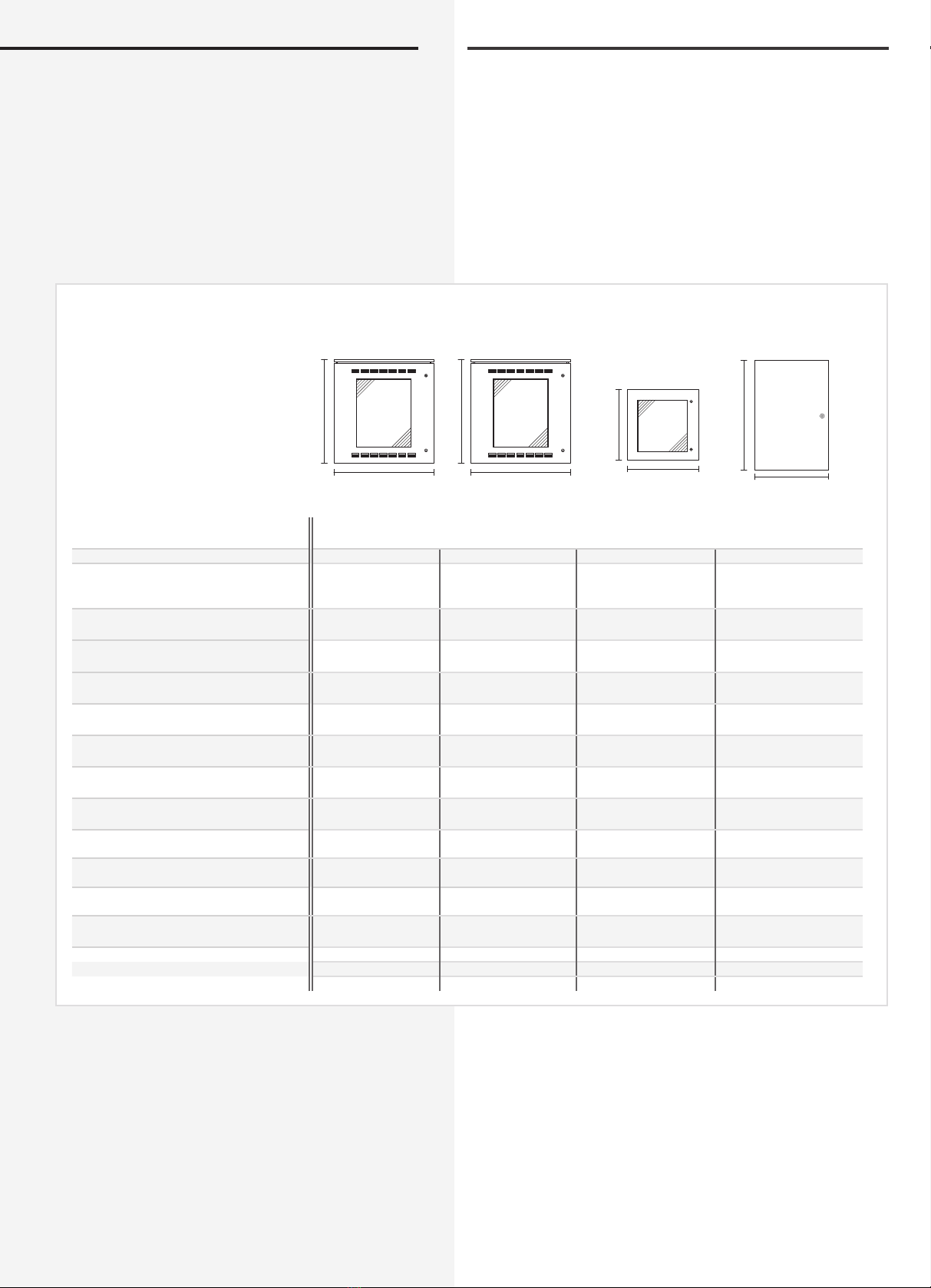
Steuerteil
Controller
Steuerteil
Controller
Netzanschluß
Mains
Netzanschluß
Mains
Batteriesicherungen
Battery fuses
Batteriesicherungen
Battery fuses
CPUS 220 / 48.1 / 5 CPUS 220 / 48.1 / 16
CPUS 220 / 48.1 / 32 CPUS 220 / 48.1 / 48
Anschlußklemmen
Terminals
Anschlußklemmen
Terminals
Stromkreismodule
Circuit modules
Stromkreismodule
Circuit modules

1 3
CPS 220/48.1/SV Montage- und Betriebsanleitung CPS 220/48.1/SV Mounting and Operating Instructions
4.2 CPUSB 220 / 48.1 / 6
CPUSB 220 / 48.1 / 16
CPUSB 220 / 48.1 / 32
CPUSB 220 / 48.1 / 48
Die BUS-Unterstationen CPUSB 220 / 48.1 / ... ermögli-
chen, externe Stromkreise an die Zentralbatteriesysteme
CPS 220 / 48.1 anzuschließen. Über die 2-adrige Bat-
terieleitung werden die BUS-Unterstationen auch bei
Netzausfall mit Spannung versorgt. Die Überwachung
und Programmierung erfolgt über das Steuerteil des Zen-
tralbatteriesystems mittels der dreiadrigen Busleitung. Bei
Ausfall der BUS-Kommunikation schalten die Stromkreis-
module in den sicheren Betriebszustand.
Um die projektspezifischen Anforderungen optimal
zu unterstützen, sind die BUS-Unterstationen
ebenfalls in unterschiedlichen Ausbaustufen
erhältlich:
CPUSB 220 / 48.1 / 6
Auf einem Modulträger können bis zu 3 Stromkreismo-
dule (2x3A) eingesetzt werden.
Adressbereich über Adressschalter einstellbar siehe
6.3.3.5. Adressierung - Seite 28
CPUSB 220 / 48.1 / 16
In einem 19“ Modulträger können bis zu 8 Stromkreismo-
dule mit unterschiedlicher Leistung (1x6A, 2x3A) einge-
setzt werden.
Adressbereich Modulträger: 1 bis 8, 9 bis 16, 17 bis 24, je
nach Ausführung
CPUSB 220 / 48.1 / 32
In zwei 19“ Modulträgern können bis zu 16 Stromkreis-
module mit unterschiedlicher Leistung (1x6A, 2x3A) ein-
gesetzt werden.
Adressbereich Modulträger 1: 1 bis 8
Adressbereich Modulträger 2: 9 bis 16
CPUSB 220 / 48.1 / 48
In drei 19“ Modulträgern können bis zu 24 Stromkreismo-
dule mit unterschiedlicher Leistung (1x6A, 2x3A) einge-
setzt werden.
Adressbereich Modulträger 1: 1 bis 8
Adressbereich Modulträger 2: 9 bis 16
Adressbereich Modulträger 3: 17 bis 24
Es ist darauf zu achten, dass jede Adresse je BUS
nur einmal verwendet werden darf!
4.2 CPUSB 220 / 48.1 / 6
CPUSB 220 / 48.1 / 16
CPUSB 220 / 48.1 / 32
CPUSB 220 / 48.1 / 48
The BUS sub stations CPUSB 220/48.1/… enable external
circuits to be connected to the central battery systems
CPS 220/48. The BUS sub stations are supplied with
power via the 2-wire supply lead, even if the power fails.
Monitoring and programming is carried out via the cen-
tral battery system controller by means of the three-wire
BUS data line. If the BUS communication fails, the circuit
modules switch to safe mode.
In order to support project-specific requirements
optimally, the BUS sub stations are also available
in various expansion levels:
CPUSB 220 / 48.1 / 6
Up to 3 circuit modules (2x3A) can be used on a module
rack.
Address range configurable via address switches see
6.3.3.5. Addressing on page 28
CPUSB 220 / 48.1 / 16
In a 19” module rack, up to 8 circuit modules with
various power values (1x6A, 2x3A) can be used.
Module rack address range: 1 to 8, 9 to 16, 17 to 24,
depending on design
CPUSB 220 / 48.1 / 32
In a 19” module rack, up to 16 circuit modules with
various power values (1x6A, 2x3A) can be used.
Module rack 1 address range: 1 to 8
Module rack 2 address range: 9 to 16
CPUSB 220 / 48.1 / 48
In a 19” module rack, up to 24 circuit modules with
various power values (1x6A, 2x3A) can be used.
Module rack 1 address range: 1 to 8
Module rack 2 address range: 9 to 16
Module rack 3 address range: 17 to 24
It is important to note that each address at every
bus may only be used once!

14
CPS 220/48.1/SV Montage- und Betriebsanleitung CPS 220/48.1/SV Mounting and Operating Instructions
14
Netz Netz
LLNSt.-Kreis1
L+N– St.-Kreis2
L+N– St.-Kreis3
L+N– St.-Kreis4
L+N– St.-Kreis5
L+N– St.-Kreis6
L+N– IBBatt. Batt. BBN
0
1
2
3
4
5
6
7
8
9
SKE - 2 x 3A
5 AT
FF
5 AT
21
= BL / NM
= DL / M
1000 1000
SKE - 2 x 3A
5 AT
FF
5 AT
21
= BL / NM
= DL / M
1000 1000
SKE - 2 x 3A
5 AT
FF
5 AT
21
= BL / NM
= DL / M
1000 1000
N-
N-
L+
L+
Geeignet für Anlagen gem. DIN VDE 0108 / 10.89
ta:
EMC:
INOTEC
ET 9/24
Eingang
+
-
U:
N
gem. EN 55015
AC 230V 50 / 60Hz
DC 176 - 260 V
-15 ... 45°C
tc
tc=75°C max
Temp.-Test
860 012
Ausgang
24V/320mA
CPUSB 220 / 48.1 / 6
Stromkreismodule
Circuit modules
SKE 2x3A
1
1000
5 AT
F
2
1000
5 AT
= BL/NM
= DL/NM
F
SKE 2x3A
1
1000
5 AT
F
2
1000
5 AT
= BL/NM
= DL/NM
F
SKE 2x3A
1
1000
5 AT
F
2
1000
5 AT
= BL/NM
= DL/NM
F
SKE 2x3A
1
1000
5 AT
F
2
1000
5 AT
= BL/NM
= DL/NM
F
SKE 2x3A
1
1000
5 AT
F
2
1000
5 AT
= BL/NM
= DL/NM
F
SKE 2x3A
1
1000
5 AT
F
2
1000
5 AT
= BL/NM
= DL/NM
F
SKE 2x3A
1
1000
5 AT
F
2
1000
5 AT
= BL/NM
= DL/NM
F
SKE 2x3A
1
1000
5 AT
F
2
1000
5 AT
= BL/NM
= DL/NM
F
SKE 2x3A
1
1000
5 AT
F
2
1000
5 AT
= BL/NM
= DL/NM
F
SKE 2x3A
1
1000
5 AT
F
2
1000
5 AT
= BL/NM
= DL/NM
F
SKE 2x3A
1
1000
5 AT
F
2
1000
5 AT
= BL/NM
= DL/NM
F
SKE 2x3A
1
1000
5 AT
F
2
1000
5 AT
= BL/NM
= DL/NM
F
SKE 2x3A
1
1000
5 AT
F
2
1000
5 AT
= BL/NM
= DL/NM
F
SKE 2x3A
1
1000
5 AT
F
2
1000
5 AT
= BL/NM
= DL/NM
F
SKE 2x3A
1
1000
5 AT
F
2
1000
5 AT
= BL/NM
= DL/NM
F
SKE 2x3A
1
1000
5 AT
F
2
1000
5 AT
= BL/NM
= DL/NM
F
SKE 2x3A
1
1000
5 AT
F
2
1000
5 AT
= BL/NM
= DL/NM
F
SKE 2x3A
1
1000
5 AT
F
2
1000
5 AT
= BL/NM
= DL/NM
F
SKE 2x3A
1
1000
5 AT
F
2
1000
5 AT
= BL/NM
= DL/NM
F
SKE 2x3A
1
1000
5 AT
F
2
1000
5 AT
= BL/NM
= DL/NM
F
SKE 2x3A
1
1000
5 AT
F
2
1000
5 AT
= BL/NM
= DL/NM
F
SKE 2x3A
1
1000
5 AT
F
2
1000
5 AT
= BL/NM
= DL/NM
F
SKE 2x3A
1
1000
5 AT
F
2
1000
5 AT
= BL/NM
= DL/NM
F
SKE 2x3A
1
1000
5 AT
F
2
1000
5 AT
= BL/NM
= DL/NM
F
Stromkreismodule
Circuit modules
CPUSB 220 / 48.1 / 16 CPUSB 220 / 48.1 / 32
Klemmen /Anschlußraum
Terminals
SKE 2x3A
1
1000
5 AT
F
2
1000
5 AT
= BL/NM
= DL/NM
F
SKE 2x3A
1
1000
5 AT
F
2
1000
5 AT
= BL/NM
= DL/NM
F
SKE 2x3A
1
1000
5 AT
F
2
1000
5 AT
= BL/NM
= DL/NM
F
SKE 2x3A
1
1000
5 AT
F
2
1000
5 AT
= BL/NM
= DL/NM
F
SKE 2x3A
1
1000
5 AT
F
2
1000
5 AT
= BL/NM
= DL/NM
F
SKE 2x3A
1
1000
5 AT
F
2
1000
5 AT
= BL/NM
= DL/NM
F
SKE 2x3A
1
1000
5 AT
F
2
1000
5 AT
= BL/NM
= DL/NM
F
SKE 2x3A
1
1000
5 AT
F
2
1000
5 AT
= BL/NM
= DL/NM
F
SKE 2x3A
1
1000
5 AT
F
2
1000
5 AT
= BL/NM
= DL/NM
F
SKE 2x3A
1
1000
5 AT
F
2
1000
5 AT
= BL/NM
= DL/NM
F
SKE 2x3A
1
1000
5 AT
F
2
1000
5 AT
= BL/NM
= DL/NM
F
SKE 2x3A
1
1000
5 AT
F
2
1000
5 AT
= BL/NM
= DL/NM
F
SKE 2x3A
1
1000
5 AT
F
2
1000
5 AT
= BL/NM
= DL/NM
F
SKE 2x3A
1
1000
5 AT
F
2
1000
5 AT
= BL/NM
= DL/NM
F
SKE 2x3A
1
1000
5 AT
F
2
1000
5 AT
= BL/NM
= DL/NM
F
SKE 2x3A
1
1000
5 AT
F
2
1000
5 AT
= BL/NM
= DL/NM
F
SKE 2x3A
1
1000
5 AT
F
2
1000
5 AT
= BL/NM
= DL/NM
F
SKE 2x3A
1
1000
5 AT
F
2
1000
5 AT
= BL/NM
= DL/NM
F
SKE 2x3A
1
1000
5 AT
F
2
1000
5 AT
= BL/NM
= DL/NM
F
SKE 2x3A
1
1000
5 AT
F
2
1000
5 AT
= BL/NM
= DL/NM
F
SKE 2x3A
1
1000
5 AT
F
2
1000
5 AT
= BL/NM
= DL/NM
F
SKE 2x3A
1
1000
5 AT
F
2
1000
5 AT
= BL/NM
= DL/NM
F
SKE 2x3A
1
1000
5 AT
F
2
1000
5 AT
= BL/NM
= DL/NM
F
SKE 2x3A
1
1000
5 AT
F
2
1000
5 AT
= BL/NM
= DL/NM
F
CPUSB 220 / 48.1 / 48
Klemmen Anschlußraum
Terminals
Stromkreismodule
Circuit modules
Klemmen Anschlußraum
Terminals
1 5
CPS 220/48.1/SV Montage- und Betriebsanleitung CPS 220/48.1/SV Mounting and Operating Instructions
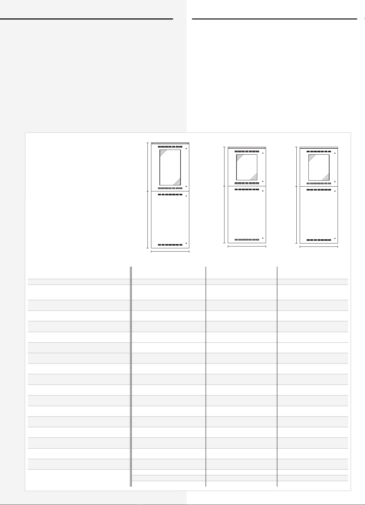
5. Technical data
5.1. CPS 220 / 48.1 / ...
CPUS 220 / 48.1 / ...
Protection class: I
Protection category: IP 20
Permissible ambient temperature:
For the device: -5°C to +35°C
For the battery: as per the battery datasheet
Battery: 216 V DC
Colour: RAL 7035
Base (option): 100/200 mm
5. Technische Daten
5.1. CPS 220 / 48.1 / ...
CPUS 220 / 48.1 / ...
Schutzklasse: I
Schutzart: IP 20
Zulässige Umgebungstemperatur:
für das Gerät: -5°C bis +35°C
für die Batterie: gem. Batteriedatenblatt
Batterie: 216V DC
Farbe: RAL 7035
Sockel (optional): 100 / 200mm
800 mm
1200 mm 830 mm
800 mm
1200 mm 1030 mm
800 mm
1200 mm 830 mm
Anschlussspannung
Rated voltage
3~N/PE, 400V AC
±10%, 50/60Hz
3~N/PE, 400V AC
±10%, 50/60Hz
1~N/PE, 230V AC
±10%, 50/60Hz
Stromkreismodule
Anzahl freier Baugruppenplätze
Free module slots
SKE 2x3A / SKE 1x6A max. intern / extern 24 / 24 16 / 24 8 / 24
Anzahl freier TE für Optionen
Space for options 6 TE 11 TE 19 TE
- bei Funktionserhalt
- with function preservation - - 19 TE
Netzeinspeisung 3-ph (optional)
Supply 3-phase (option) ja / yes ja / yes ja/ yes
max. inst. Batterie Kapazität
Max. installed battery capacity 75 Ah 75 Ah 75 Ah
Max. Anschlussquerschnitt (mm²) für:
Conductor cross section, max. (mm²)
Netzzuleitung
Mains supply 35 35 35
Batteriezuleitung
Battery supply 35 35 35
Lichtstromkreise
Outgoing to luminaires 4 4 4
Datenleitung (RTG)
Outgoing data line (RTG) 4 4 4
24V Stromschleife
Outgoing 24V monitoring 4 4 4
Netzleitung für Unterstation
Outgoing mains to CPUS 35 35 35
Batterieleitung für Unterstation
Outgoing battery to CPUS 35 35 35
Abmessungen: H x B x T (mm)
Dimensions H x W x D (mm) 2230 x 800 x 400 2030 x 800 x 400 2030 x 800 x 400
Funktionserhalt (optional)
With function preservation (option) - BRS 10.1 *1 BRS 10.1 *1
- bei Funktionserhalt
- with function preservation - 2346 x 894 x 586 2346 x 894 x 586
Kabeleinführungen
Cable inlets 22 x M 20 22 x M 20 22 x M 20
64 x M 25 64 x M 25 64 x M 25
6 x M 32 6 x M 32 6 x M 32
2 x M 50 2 x M 50 2 x M 50
CPS 220 / 48.1 / 48 CPS 220 /48.1 / 32 CPS 220 / 48.1 / 16
16
CPS 220/48.1/SV Montage- und Betriebsanleitung CPS 220/48.1/SV Mounting and Operating Instructions
16
Sockel
1000 mm 600 mm
100 mm
600 mm
600 mm
600 mm 600 mm
Sockel
1000 mm 800 mm
100 mm
600 mm
830 mm
800 mm
CPS 220 / 48.1 / 11 CPS 220 / 48.1 / 5 CPUS 220 / 48.1 / 48
Anschlussspannung
Rated voltage
1~N/PE, 230V AC
±10%, 50/60Hz
1~N/PE, 230V AC
±10%, 50/60Hz
1~N/PE, 230V AC ±10%,
50/60Hz
Stromkreismodule
Anzahl freier Baugruppenplätze
Free module slots
SKE 2x3A / SKE 1x6A max. intern / extern
11 / - 5 *2/ - 24 / 24
Anzahl freier TE für Optionen
Space for options 6 TE 9 TE 9 TE
- bei Funktionserhalt
- with function preservation 6 TE 9 TE -
Netzeinspeisung 3-ph (optional)
Supply 3-phase (option) - - ja/ yes
max. inst. Batterie Kapazität
Max. installed battery capacity 27,8 Ah 27,8 Ah -
Max. Anschlussquerschnitt (mm²) für:
Conductor cross section, max. (mm²)
Netzzuleitung
Mains supply 16 16 35
Batteriezuleitung
Battery supply 35 35 35
Lichtstromkreise
Outgoing to luminaires 4 4 4
Datenleitung (RTG)
Outgoing data line (RTG) 4 4 4
24V Stromschleife
Outgoing 24V monitoring 4 4 4
Netzleitung für Unterstation
Outgoing mains to CPUS - - -
Batterieleitung für Unterstation
Outgoing battery to CPUS - - -
Abmessungen: H x B x T (mm)
Dimensions H x W x D (mm) 1800 x 600 x 300 1600 x 600 x 300 830 x 800 x 400
Funktionserhalt (optional)
With function preservation (option) BRS 10.1 *1 BRS 10.1 *1 BRS 08
- bei Funktionserhalt
- with function preservation 2346 x 894 x 586 2346 x 894 x 586 1374 x 624 x 434
Kabeleinführungen
Cable inlets 4 x M 32 4 x M 40 22 x M 20
33 x M 25 33 x M 25 64 x M 25
10 x M 20 10 x M 20 6 x M 32
2 x M 50
*1 max. 55 Ah
*2 max. 4 Baugruppenplätze bei TFT-Steuerteil
*1 max. 55 Ah battery
*2 max. 4 slots usable in combination with TFT controller unit
1 7
CPS 220/48.1/SV Montage- und Betriebsanleitung CPS 220/48.1/SV Mounting and Operating Instructions
600 mm
600 mm
600 mm
600 mm
830 mm
800 mm
CPUS 220 / 48.1 / 32 CPUS 220 / 48.1 / 16 CPUS 220 / 48.1 / 5
Anschlussspannung
Rated voltage
1~N/PE, 230V AC ±10%,
50/60Hz
1~N/PE, 230V AC ±10%,
50/60Hz
1~N/PE, 230V AC ±10%,
50/60Hz
Stromkreismodule
Anzahl freier Baugruppenplätze
Free module slots
SKE 2x3A / SKE 1x6A max. intern / extern
16 / 24 8 / 24 5 *2/ -
Anzahl freier TE für Optionen
Space for options 14 TE 8 TE 9 TE
- bei Funktionserhalt
- with function preservation 2 TE 7 TE 8 TE
Netzeinspeisung 3-ph (optional)
Supply 3-phase (option) ja / yes - -
max. inst. Batterie Kapazität
Max. installed battery capacity - - -
Max. Anschlussquerschnitt (mm²) für:
Conductor cross section, max. (mm²)
Netzzuleitung
Mains supply 35 35 35
Batteriezuleitung
Battery supply 35 35 35
Lichtstromkreise
Outgoing to luminaires 4 4 4
Datenleitung (RTG)
Outgoing data line (RTG) 4 4 4
24V Stromschleife
Outgoing 24V monitoring 4 4 4
Netzleitung für Unterstation
Outgoing mains to CPUS - - -
Batterieleitung für Unterstation
Outgoing battery to CPUS - - -
Abmessungen: H x B x T (mm)
Dimensions H x W x D (mm) 830 x 800 x 400 600 x 600 x 300 600 x 600 x 300
Funktionserhalt (optional)
With function preservation (option) BRS 08 BRS 08 BRS 08
- bei Funktionserhalt
- with function preservation 1374 x 624 x 434 1374 x 624 x 434 1374 x 624 x 434
Kabeleinführungen
Cable inlets 22 x M 20 4 x M 40 4 x M 40
64 x M 25 33 x M 25 33 x M 25
6 x M 32 10 x M 20 10 x M 20
2 x M 50
*1 max. 55 Ah
*2 max. 4 Baugruppenplätze bei TFT-Steuerteil
*1 max. 55 Ah battery
*2 max. 4 slots usable in combination with TFT controller unit
18
CPS 220/48.1/SV Montage- und Betriebsanleitung CPS 220/48.1/SV Mounting and Operating Instructions
18
5.2. CPUSB 220 / 48.1/ ...
Schutzklasse: I
Schutzart: IP 20
Zulässige Umge-
bungstemperatur: -5°C bis +35°C
Kabeleinführung von oben
830 mm
800 mm
830 mm
800 mm
600 mm
600 mm
400 mm
600 mm
CPUSB 220/48.1/32CPUSB 220/48.1/48 CPUSB 220/48.1/16 CPUSB 220/48.1/6
Anschlussspannung
Rated voltage
1~N/PE, 230V AC ±10%, 50/60Hz
216V DC +10%/-15%
Stromkreismodule
Anzahl freier Baugruppenplätze
Free module slots
SKE 2x3A / SKE 1x6A
24 16 8 3 (nur 2x3A)
Anzahl freier TE für Optionen
Space for options 15 TE / 2TE (BRS08) 20 TE / 7 TE (BRS08) 13 TE / 12 TE (BRS08) -
Netzeinspeisung 3-ph (optional)
Supply 3-phase (option) ja/ yes ja/ yes - -
Max. Anschlussquerschnitt (mm²) für:
Conductor cross section, max. (mm²)
Netzzuleitung
Mains supply 35 35 35 10
Batteriezuleitung
Battery supply 35 35 35 10
Lichtstromkreise
Outgoing to luminaires 4 4 4 4
BUS-Leitung IB2
BUS IB2 4 4 4 4
Abmessungen: H x B x T (mm)
Dimensions H x W x D (mm) 830 x 800 x 400 830 x 800 x 400 600 x 600 x 300 600 x 400 x 150
Funktionserhalt (optional)
With function preservation (option) BRS 08 BRS 08 BRS 08 BRS 06
- bei Funktionserhalt
- with function preservation 1374 x 624 x 434 1374 x 624 x 434 1374 x 624 x 434 1074 x 624 x 334
Kabeleinführungen
Cable inlets 22 x M 20 20 x M 20 10 x M20 13 x M25
64 x M 25 64 x M 25 33 x M 25 4 x M 35
6 x M 35 6 x M 35 4 x M 35
2 x M 50 2 x M 50
*1 max. 55 Ah
*2 max. 4 Baugruppenplätze bei TFT-Steuerteil
*1 max. 55 Ah battery
*2 max. 4 slots usable in combination with TFT controller unit
5.2. CPUSB 220 / 48.1 / ...
Protection class: I
Protection category: IP 20
Permissible ambient
temperature:
-5°C to +35°C
Cable inlets from top

1 9
CPS 220/48.1/SV Montage- und Betriebsanleitung CPS 220/48.1/SV Mounting and Operating Instructions
6. Aufstellung, Anschluss
Beachten Sie für die Lagerung der Komponenten
bis zur Montage die Hinweise in
siehe 3.2. Lagerung - Seite 7
Bei der Montage des Gerätes ist auf ausreichende
Tragfähigkeit des Bodens oder der entsprechen-
den Montagewand sowie auf geeignetes Monta-
gematerial (Dübel) zu achten.
Bei der Auslieferung des Systems ist auf dem
obersten Baugruppenträger des Elektronik-
schranks eine Abdeckung zum Schutz vor Eindrin-
gen von Fremdteilen (Verdrahtungsreste) aufgeklebt.
Diese ist nach der Installation und vor dem Einschalten
des Systems zu entfernen.
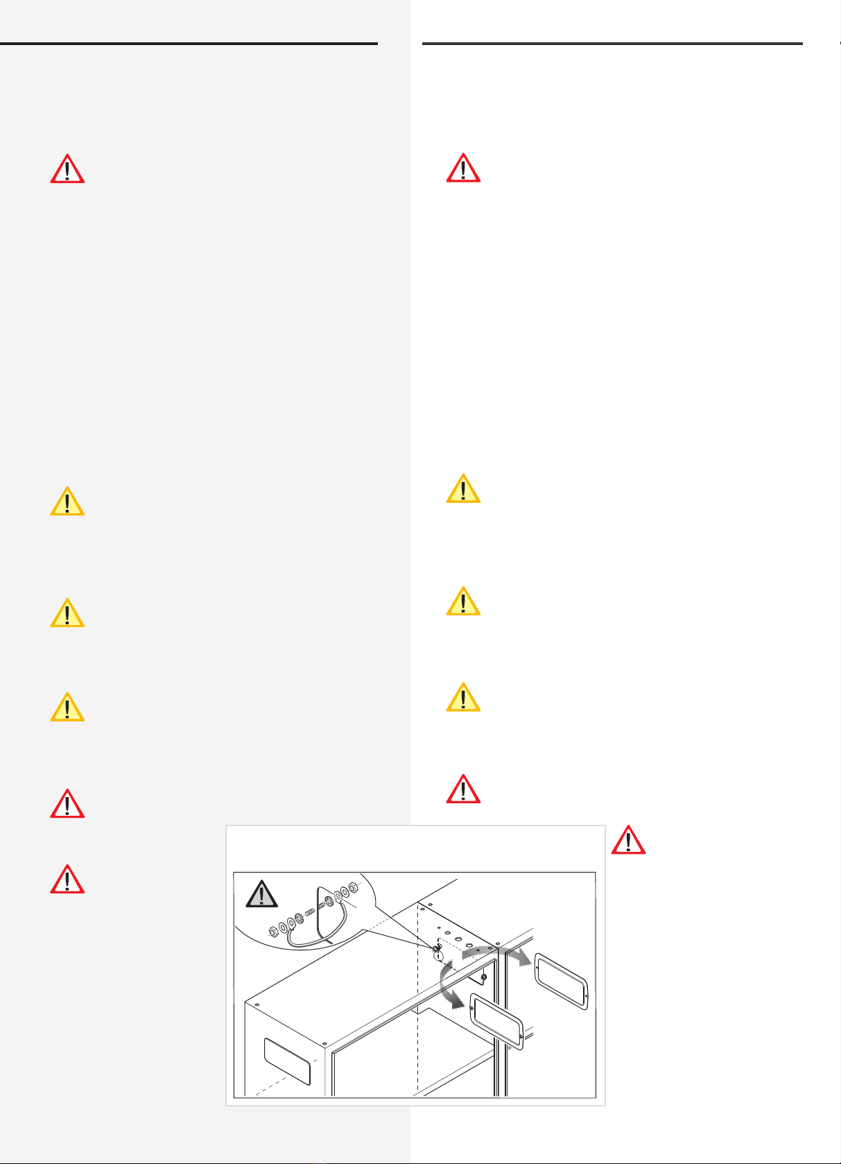
6.1.1. CPS 220 / 48.1 / ..., CPUS 220 / 48.1 / ...,
CPUSB 220 / 48.1 / ...
Der Elektronik- und Batterieschrank
werden am Aufstellungsort aufeinan-
der gesetzt und mit dem beiliegenden
Schrauben verbunden. Um den notwen-
digen Abstand zur Wand zu gewährleis-
ten, wird der Schrank mit den beigeleg-
ten Wandbefestigungslaschen an der
Wand befestigt.
Für die Batterielei-
tungen sind die zwei
Verschraubungen (bei
parallel geschalteten
Batteriesätzen vier
Verschraubungen)
zwischen Elektronik-
und Batterieschrank
zu montieren. Der
Temperaturfühler ist
in der dritten Bohrung
zu montieren. Wird
das BCS-System oder
Temperatur-Switch
(bei mehr als 1 Batte-
rieschrank) eingesetzt,
so ist die zusätzli-
che Verschraubung
ebenfalls zwischen
Elektronik- und Batte-
rieschrank zu montieren.
Die korrekte Aufstellung und Montage von Gerä-
ten im E30-Gehäuse entnehmen Sie bitte der ent-
sprechenden Bedienungsanleitung!
4x
Unterlegscheibe
Washer
007 938 2 x
Temperaturfühler
Temperature sensor
069 012
Batterie-Kabelkanal
Cable duct
Temperaturfühler
Temperature sensor
Mutter
Nut
007 923
850 009
Temperaturfühler
Temperature sensor
Kabelführung
Cable gride
Batterieschrank
Battery cabinet
Elektronikschrank
Electronic cabinet
6. Assembly, connection
For storage of the components through to assem-
bly, observe the information in
see 3.2. Storage on page 7
When assembling the device, adequate load-bear-
ing capacity of the floor or mounting wall and suit-
able assembly material (dowels) must be ensured.
When the system is shipped, a cover is taped onto
the top-most component rack of the electrical
cabinet to prevent the entry of foreign bodies
(wiring scraps). This must be removed after the installa-
tion and before activation of the system.
6.1.1. CPS 220 / 48.1 / ..., CPUS 220 / 48.1 / ...,
CPUSB 220 / 48.1 / ...
The electronics and battery cabinets
are placed on top of one another at
the assembly site and connected with
the screws supplied. To guarantee the
required clearance to the wall, the cabi-
net is fastened to the wall with the wall-
mounting straps provided.
For the battery cables
and the optional tem-
perature sensor, the
three screw connec-
tions (for battery sets
connected in parallel,
five screw connections)
are to be mounted
between the electron-
ics cabinet and the
battery cabinet. If no
temperature sensor is
used, the third screw
connection must be
sealed off with a blank
plug (supplied).
Please see the relevant operating instructions for
correct installation and assembly of devices in the
E30 housing!
20
CPS 220/48.1/SV Montage- und Betriebsanleitung CPS 220/48.1/SV Mounting and Operating Instructions
20
6.2. Battery
Please check the supplied batteries, connector and bat-
tery cable for completeness and mechanical damage.
Before connecting the batteries, battery fuses F1
and F2 must be removed. The relevant safety regu-
lations concerning high DC voltage must be
observed. The battery fuses F1 and F2 may be inserted
only when installation of the entire CPS system is com-
plete
see 7. Commissioning on page 47
Insert the batteries in the cabinet as shown in the follow-
ing diagrams, attach them to the connectors and place
the protective caps over the pins. Please see the separate
documentation for fitting batteries in the 2 m upright
cabinet or onto battery racks.
For fitting batteries in two or more battery cabinets,
the side flange plates must be removed to enable wiring
as shown in the diagram.
The battery cabinets must be connected with the sup-
plied earthing cables.
The battery instructions are part of the operating
instructions and must be kept in a safe place. Addi-
tional information on inspection and care of the
maintenance-free batteries can be found in the battery
instructions supplied.
When using a BCS system, the Faston adapters
must be affixed below the cell connector as shown
in the diagram. The adapters are part of the BCS
sensors.
When using a BCS system, the Faston adapters
must be affixed below the cell connector as shown
in the diagram. The adapters are part of the BCS
sensors.
Improper handling can cause potentially fatal inju-
ries! The battery voltage is 216 V.
Attention must be
paid to correct polar-
ity when connecting
the battery!
6.2. Batterie
Bitte überprüfen Sie die gelieferten Batterien, Polverbin-
der und Batteriekabel auf Vollständigkeit und mechani-
sche Beschädigungen.
Vor Anschluss der Batterien sind die Batteriesiche-
rungen F1 und F2 zu entfernen. Die entsprechen-
den Sicherheitsbestimmungen betreffend hoher
Gleichspannung sind zu beachten. Erst wenn die Installa-
tion des gesamten CPS-Systems abgeschlossen ist, sind
die Batteriesicherungen F1 und F2 einzusetzen.
siehe 7. Inbetriebnahme - Seite 47
Die Batterien gemäß der folgenden Abbildungen in den
Schrank einsetzen, mit den Polverbindern verschalten und
die Schutzkappen auf die Pole setzen. Für die Montage
von Batterien im 2m Standschrank oder auf Batteriege-
stellen beachten Sie bitte die gesonderte Dokumentation.
Für die Montage von Batterien in zwei oder mehr
Batterieschränken sind für die Verdrahtung die seitlichen
Flanschplatten gemäß Zeichnung zu entfernen.
Die Batterieschränke sind mit den mitgelieferten Erdungs-
leitungen zu verbinden.
Die Batteriehinweise sind Bestandteil der Bedie-
nungsanleitung und müssen aufbewahrt werden.
Weitere Hinweise zur Inspektion und Pflege der
wartungsfreien Batterien entnehmen Sie den mitgeliefer-
ten Batterieinstruktionen.
Es dürfen nur Batterien verwendet werden, die
eine angegebene Lebensdauererwartung von
mindestens 10 Jahren bei 20°C Umgebungstempe-
ratur haben.
Beim Einsatz eines BCS-Systems sind die Faston-
Adapter gemäß Zeichnung unterhalb der Polver-
binder zu befestien. Die Adapter sind Bestandteil
der BCS-Sensoren.
Unsachgemäße Handhabung kann zu lebensge-
fährlichen Verletzungen führen! Die Batteriespan-
nung beträgt 216V.
Bei Anschluß der Bat-
terie ist auf die richtige
Polung zu achten!
Die Flanschplatten bei Bedarf entfernen.
Remove cover plate if required.
Other manuals for CPS 220/48.1 Series
1
This manual suits for next models
15
Table of contents
Popular Portable Generator manuals by other brands


Unit
Unit UTG900E Series user manual

Z.I.P.P.ER MASCHINEN
Z.I.P.P.ER MASCHINEN ZI-STE2800 user manual

MQ Power
MQ Power Ultra-Silent DCA-150USJ Operation and parts manual

Powerline
Powerline TGE 3000 Ti user manual

MQ Power
MQ Power WHISPERWATT DCA220SSJU4F3PD Operation manual

Power Stroke
Power Stroke PS905700D Operator's manual